
Related Manuals for Curtis RU-150-20


Summary of Contents for Curtis RU-150-20
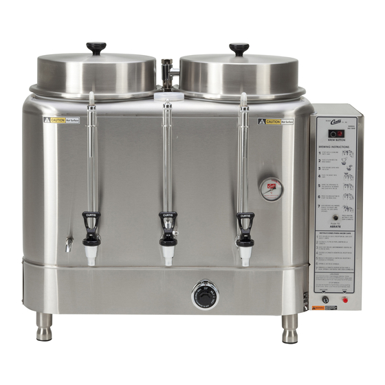
- Page 1 USER GUIDE RU Series Automatic Coffee Urn Style Varies, RU-300 Shown READ AND SAVE THESE INSTRUCTIONS NOTICE TO INSTALLER: Please leave this booklet with the machine.
-
Page 2: Table Of Contents
.....................................................ES81 ......................ES82 ..............................................................................................Contact Information Wilbur Curtis Co., Inc. 6913 Acco Street | Montebello, CA 90640 US Phone: 323-837-2300 | Toll Free: 800-421-6150 Email: csrassistance@wilburcurtis.com | Web: www.wilburcurtis.com . - 4:00 . PT Email: techsupport@wilburcurtis.com... -
Page 3: Fs38
KEY FEATURES/SPECIFICATIONS/SYSTEM REQUIREMENTS FS38 Key Features • • • • Single 3 Gallon 1 PH 220 V 21.1 A 2 X 2500 W 3W + G 5000 50/60 Hz 13.0 1 X 3 Gal. Single 3 Gallon, 3 Phase 3 PH 220 V 13.8 A 3 X 1750 W... -
Page 4: Is2
INSTRUCTIONS could result in personal injury or void the warranty. • This appliance is designed for commercial use. Any service other than cleaning and preventive maintenance should be performed by an authorized Wilbur Curtis service technician. • serviceable parts inside. - Page 5 IMPORTANT SAFEGUARDS CE Requirements • This appliance must be installed in locations where it can be overseen by trained personnel. • • • • This appliance must not be cleaned by water jet. • instruction concerning use of the appliance in a safe way and if they understand the hazards involved. •...
-
Page 6: Ii2
INSTALLATION INSTRUCTIONS WARNING: WARNING: properly grounded. NOTICE: SPECIFICATIONS section. IMPORTANT: Installation Instructions Installation Requirements • A secure surface capable of supporting the weight of the appliance. • For units without an attached cord set: Appropriately sized, UL listed, grounding type power cable to meet enough •... -
Page 7: Ii7
INSTALLATION INSTRUCTIONS Installation Prepare the Location WARNING: DO NOT place the urn closer than 6 inches from the wall. The urn must have adequate cross-ventilation. Determine the location. Make sure that the counter is capable of supporting at least 600 lbs. to allow for the urn weight at full capacity. - Page 8 INSTALLATION INSTRUCTIONS Connect the Water Supply Flush the water supply line prior to installation to Back of back of the urn control panel. Leave the water supply valve closed until power is connected. Connect the Wiring WARNING: Turn off power to the junction box at the circuit breaker panel before connecting the power cable to the urn.
- Page 9 INSTALLATION INSTRUCTIONS Power Up the Brewer 15 Turn on the water supply valve. 16 Make sure that the circuit breaker(s) supplying power to the unit is on. Turn the main power toggle switch on the bottom of the urn control box to the ON position. When you turn the toggle switch ON, the water jacket will start to Thermostat and water supply tubing.
-
Page 10: Oi31
OPERATING INSTRUCTIONS OI31 Brewing Instructions WARNING - TO AVOID SCALDING, AVOID SPLASHING. Keep body parts clear of hot surfaces on the outside of the urn. The urn is factory preset for optimal performance. Thermostat Main power switch The brewer should be Remove the urn lid and rotate Remove the brew basket and the spray arm to the side. - Page 11 OPERATING INSTRUCTIONS OI31 Aeration During brewing, the richer, thicker coffee tends to settle toward the bottom of the liner, while the weaker part of the mixture tends to move to the top. The aeration feature assures uniform mixing of the brewed coffee by pumping air brew cycle.
-
Page 12: Ci4
CLEANING INSTRUCTIONS NOTICE - Do not use cleaning liquids, compounds or powders containing acids or corrosives. These products promote corrosion and will pit the stainless steel. Never use abrasives to clean the unit(s). USE OF THESE PRODUCTS WILL VOID THE WARRANTY. Daily Cleaning - Urns and Banquet Brewer without Banquet Holder* WARNING: Avoid injury. -
Page 13: Ci18
CLEANING INSTRUCTIONS CI18 Cleaning the Faucet and Sight Gauge - As Needed Unscrew the handle/bonnet assembly and remove. Inspect the seat cup for wear. Replace the seat cup if it is damaged. Clean the parts with a mild detergent solution. Handle Rinse, dry and reassemble the handle/bonnet by hand. - Page 14 ROUGH-IN DRAWINGS RD44 RU-150 Series 6.38 in 8.75 in [16.2 cm] [22.2 cm] 4.25 in [10.8cm] 20.50 in 23.75 in [52.1 cm] [60.3 cm] 16.50 in 19.38 in [41.9 cm] [49.2 cm] 29.25 in [74.30 cm] 9.75 in [24.8 cm] 3.25 in 3.38 in [8.3 cm]...
- Page 15 ROUGH-IN DRAWINGS RD44 RU-225 Series 6.38 in 8.63 in [16.2 cm] [21.9 cm] 4.25 in [10.8cm] 20.50 in 23.50 in [52.1 cm] [59.7 cm] 16.50 in 19.25 in [41.9 cm] [48.9 cm] 32.50 in [82.6 cm] 9.75 in [24.8 cm] 3.25 in 3.38 in [8.3 cm]...
- Page 16 ROUGH-IN DRAWINGS RD44 RU-300 Series 14.00 in [35.6 cm] 7.10 in 7.00 in 7.00 in 7.00 in [18.0 cm] [17.8 cm] [17.8 cm] [17.8 cm] 32.60 in 18.50 in [82.8 cm] [47.0 cm] 28.10 in 14.30 in [71.4 cm] [36.3 cm] 28.40 in [72.1 cm] 9.00 in...
- Page 17 ROUGH-IN DRAWINGS RD44 RU-600 Series 16.50 in [41.9 cm] 8.63 in 8.25 in 8.25 in 8.63 in [21.9 cm] [21.0 cm] [21.0 cm] [21.9 cm] 21.50 in [54.6 cm] 38.00 in [96.5 cm] 17.00 in 33.75 in [43.2 cm] [85.7 cm] 32.50 in [82.6 cm] 9.75 in...
- Page 18 ROUGH-IN DRAWINGS RD44 RU-1000 Series 16.00 in [40.6 cm] 8.50 in 8.50 in 8.50 in 8.50 in [21.6 cm] [21.6 cm] [21.6 cm] [21.6 cm] 21.50 in 38.00 in [54.9 cm] [96.5 cm] 34.00 in 17.00 in [86.4 cm] [43.2 cm] 29.50 in [74.9 cm] 9.50 in...
- Page 19 ILLUSTRATED PARTS/RECOMMENDED PARTS IP69 RU Series Urn - Control Box - Exploded View Older models: when reconnecting the silicone tubing to the copper tubes, make sure you do not cover the small holes on the copper tubes. RU AUTOMATIC, ILLUSTRATED PARTS/RECOMMENDED PARTS 101817NC...
- Page 20 WC-3900 LABEL, INSTRUCTION PANEL RU-150 RU-225 1 WC-3901 LABEL, INSTRUCTION PANEL RU225 RU-300 1 WC-3902 LABEL, INSTRUCT’S PANEL CURTIS RU-300 RU-600 1 WC-3903 LABEL, INSTRUCT’S PANEL CURTIS RU-600 RU-1000 1 WC-3904 LABEL, INSTRUCT’S PANEL CURTIS RU1000 RU-150 2 , RU-300 2...
- Page 21 ILLUSTRATED PARTS LIST IP69 RU Series Urn - Control Box - Parts List (continued) ITEM # PART # DESCRIPTION USED ON WC-5502-01 KIT, PROBE, ASSY WATER LEVEL W/HEX FITTING, O-RING & NUT ALL RU UNITS WC-405R-101K-120 KIT, AGITATION TIMER 120V RU-150,225,300,600,1000 DOMESTIC RU UNITS WC-405R-101K-220 KIT, AGITATION TIMER 220V RU-150,225,300,600,1000...
- Page 22 ILLUSTRATED PARTS/RECOMMENDED PARTS IP69 RU Series Urn - Main Chassis - Exploded View Heating element(s): with model, see Heating Elements Parts List page. Spray arm: size varies with model, see Spray Arms Parts List page. Faucet assemblies: model, see Faucet Assembly Parts List page.
- Page 23 ILLUSTRATED PARTS LIST IP69 RU Series Urn - Main Chassis - Parts List ITEM # PART # DESCRIPTION USED ON WC-3205 KNOB, LID 1/4-20 FEMALE THRD USE ON WC-5601/5602/5603 ALL RU UNITS WC-5601 LID, LINER ASSY (SC)RU-150/300 (INCLUDES KNOB) RU-150, RU-300 WC-5603 LID, LINER ASSY RU225/600/1000 (INCLUDES KNOB) RU-225, RU-600, RU-1000...
- Page 24 RU-600-12, RU-600-63, RU-1000-12 WC-13365 HARNESS ASSY RU-600-20/RU1000-20 FOR THERMOSTAT (NOT SHOWN) RU-600-20, RU-1000-20 WC-13366 HARNESS ASSY RU-150-20/225-20 FOR THERMOSTAT (NOT SHOWN) RU-150-20, RU-150-91, RU-225-20 WC-13368 HARNESS ASSY RU-300-20 FOR THERMOSTAT (NOT SHOWN) RU-300-20, RU-300-91, RU-600-91, RU-1000-91 RU AUTOMATIC, ILLUSTRATED PARTS/RECOMMENDED PARTS...
- Page 25 ILLUSTRATED PARTS/RECOMMENDED PARTS IP69 RU Series Urn - Faucet Assemblies - Exploded View RU AUTOMATIC, ILLUSTRATED PARTS/RECOMMENDED PARTS 101817NC...
- Page 26 SHIELD, 19” GAUGE GLASS 1/8 NPT RU-1000 WC-1900 VALVE, GAUGE SHIELD SHUT-OFF 1/8 NPT ALL RU UNITS WC-1800 FAUCET,”S” SERIES BLK LOCKING 1-1/32-14 UNS CURTIS ALL RU UNITS WC-1805 SEAT CUP, “S” FAUCET USE ON WC-1800/B/LB/D/DL/L/WC-1803 ALL RU UNITS WC-3705...
- Page 27 ILLUSTRATED PARTS LIST IP69 RU Series Urns - Spray Arms - Exploded View RU Series Urns - Spray Arms - Parts List ITEM # PART # DESCRIPTION ITEM # PART # DESCRIPTION WC-2908K KIT, SPRAY ARM ASSY RU-150/300 WASHER, 7/8” INTERNAL TOOTH LOCK 410 WC-4310 STAINLESS STEEL WC-2909...
- Page 28 DESCRIPTION RU-150-12 208/220V-1 PHASE WC-913-01 ELEMENT, HEATING 5KW 220V FOR MED SPIRAL LEFT WC-907-01 ELEMENT, HEATING 1.75KW 220V FORMED LEFT RU-150-20 208/220V-3 PHASE CENTER WC-907-02 ELEMENT, HEATING 1.75KW 220V FORMED CENTER RIGHT WC-907-03 ELEMENT, HEATING 1.75KW 220V FORMED RIGHT RU-150-62...
-
Page 29: Es51
ELECTRICAL SCHEMATICS ES51 RU Series Control Circuit RU CONTROL CIRCUIT, ELECTRICAL SCHEMATIC 110217NC... - Page 30 ELECTRICAL SCHEMATICS ES76 RU Series Heater Circuit, RU-150-12 RU HEATER CIRCUIT #10, ELECTRICAL SCHEMATIC 110217NC...
-
Page 31: Es77
ELECTRICAL SCHEMATICS ES77 RU Series Heater Circuit, RU-225-12, RU-300-12, RU-600-12 RU HEATER CIRCUIT #1, ELECTRICAL SCHEMATIC 110217NC... -
Page 32: Es78
ELECTRICAL SCHEMATICS ES78 RU Series Heater Circuit, RU-1000-12 RU HEATER CIRCUIT #3, ELECTRICAL SCHEMATIC 111017NC... - Page 33 ELECTRICAL SCHEMATICS ES79 RU Series Heater Circuit, RU-150-20, RU-225-20, RU-300-20, RU-600-20, RU-1000-20 RU HEATER CIRCUIT #12, ELECTRICAL SCHEMATIC 111017NC...
- Page 34 ELECTRICAL SCHEMATICS ES80 RU Series Heater Circuit, RU-150-62 RU HEATER CIRCUIT #11, ELECTRICAL SCHEMATIC 110217NC...
-
Page 35: Es81
ELECTRICAL SCHEMATICS ES81 RU Series Heater Circuit, RU-300-63, RU-600-63 RU HEATER CIRCUIT #2, ELECTRICAL SCHEMATIC 110217NC... -
Page 36: Es82
ELECTRICAL SCHEMATICS ES82 RU Series Heater Circuit, RU-150-91, RU-300-91, RU-600-91, RU-1000-91 RU HEATER CIRCUIT #5, ELECTRICAL SCHEMATIC 110217NC... - Page 37 TROUBLESHOOTING GUIDE TG20 WARNING: Electric Shock Hazard - Scald and Burn Hazard - Troubleshooting Guidelines • • Use this troubleshooting guide along with the appropriate ELECTRICAL SCHEMATIC. • No Power - Nothing Works Urn Does Not Start to Brew When BREW BUTTON is Pressed Brewing Stops When BREW BUTTON is released Water Jacket Does Not Fill...
- Page 38 TROUBLESHOOTING GUIDE TG20 Setting the Brew Timer (Brew Volume) Liner Not Filled To Normal Level During Brewing Water Jacket Does Not Fill Setting the Brew Timer Brew Light Does Not Come on During Brewing Setting the Brew Timer Water Jacket Does Not Fill IMPORTANT:...
- Page 39 TROUBLESHOOTING GUIDE TG20 Water Jacket Does Not Fill (cont.) Air Does Not Flow Through One (or Both) Tubes When AERATE Button is Pressed IMPORTANT: Automatic Aeration Does Not Work, Manual (AERATE) Button Works OK Coffee Does Not Flow Back Into Gauge After Aeration...
- Page 40 TROUBLESHOOTING GUIDE TG20 Older models: when reconnecting the silicone tubing to the copper tubes, make sure you do not cover the small holes. Air pump...
- Page 41 TROUBLESHOOTING GUIDE TG30 Water Does Not Heat At All If the water heats, but is not hot enough, see Water Not Hot Enough. • The following steps are performed with the control box toggle switch in the ON position. Check for power across the terminals of the heating element(s). If power is being supplied, remove the wires and check for an open heating element (nominal resistance is 13 Ohms).
- Page 42 TROUBLESHOOTING GUIDE TG37 Thermostat Adjustment The thermostat is factory set to cut off at 200ºF. If necessary, adjust it as follows: Turn the main power switch OFF. Rotate the thermostat knob to the right, to the BOIL position. Pull off the knob. In the thermostat stem, locate the tiny adjustment screw.
- Page 43 Return Merchandise Authorization (RMA): All returned equipment must be properly re-packaged in the original carton and received by Curtis within 45 days following the issuance of a RMA. NO UNITS OR PARTS WILL BE ACCEPTED WITHOUT A RETURN MERCHANDISE AUTHORIZATION (RMA).