Table of Contents
Advertisement
Quick Links
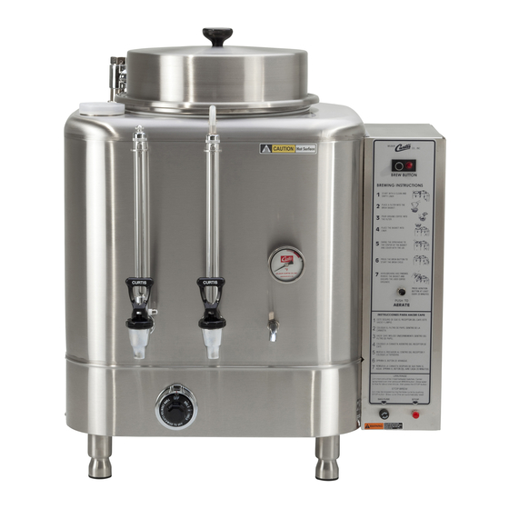
MODELS INCLUDED
• RU-150
• RU-225
• RU-300
• RU-600
• RU-1000
WARNING: DO NOT
place this urn closer than
six [6] inches from wall.
Urn must have adequate
cross-ventilation.
CAUTION: DO NOT
connect this urn to hot
water. The inlet valve is
not rated for hot water.
WARNING HOT LIQUID,
Scalding may occur.
Avoid splashing.
ISO 9001 REGISTERED
WILBUR CURTIS CO.
Montebello, CA 90640
Service Manual
RU Series Automatic Urns
Important Safeguards/Conventions
This appliance is designed for commercial use.
Any servicing other than cleaning and maintenance
should be performed by an authorized Wilbur Curtis
service center.
• To reduce the risk of fire or electric shock,
do NOT open side or bottom panel. No user
serviceable parts inside.
Repair should be performed only by autho-
rized service personnel.
• Keep hands and other items away from hot
parts of unit during operation.
• Never clean with scouring powders, bleach or
harsh implements.
Conventions
WARNINGS – To help avoid personal injury
Important Notes/Cautions – from the factory
Sanitation Requirements
The RU Automatic Urn is Factory Pre-Set and Ready to Go... Right from the Carton.
Factory Settings:
• Brew Temperature = 200°F
• Brew Volume = Set to requirements of coffee liner
System Requirements
• Water Source: 20 – 100 psi (Min Flow Rate of 1 gpm)
• Electrical: See attached schematic for standard model or visit www.wilburcurtis.com for your
model.
CAUTION: Please use the setup procedures in this manual before attempting to use brewer. Failure
to follow the instructions can result in injury or the voiding of the warranty.
BREWING INSTRUCTIONS
1. Place filter in basket. Pour cof-
fee into filter. Place basket into
liner.
FOR THE LATEST SPEC INFORMATION GO TO WWW.WILBURCURTIS.COM
for
2. Rotate sprayhead over bed of
coffee inside filter.
3. Press the BREW button on
control panel to begin brewing.
Advertisement
Table of Contents

Related Manuals for Curtis RU Series


Summary of Contents for Curtis RU Series
- Page 1 Service Manual RU Series Automatic Urns Important Safeguards/Conventions This appliance is designed for commercial use. MODELS INCLUDED Any servicing other than cleaning and maintenance should be performed by an authorized Wilbur Curtis • RU-150 service center. • RU-225 • To reduce the risk of fire or electric shock, • RU-300 do NOT open side or bottom panel. No user • RU-600 serviceable parts inside. • RU-1000 Repair should be performed only by autho- rized service personnel. • Keep hands and other items away from hot parts of unit during operation. • Never clean with scouring powders, bleach or harsh implements. Conventions WARNINGS – To help avoid personal injury Important Notes/Cautions – from the factory Sanitation Requirements The RU Automatic Urn is Factory Pre-Set and Ready to Go… Right from the Carton.
-
Page 2: Packing List
WATER SUPPLY All Curtis Automatic Urns are equipped with a ¼” male flare fitting which must be connected to the water supply with a ¼” copper tubing and a ¼” flare nut. It is recommended that some type of water strainer be used in the water line before entering the unit. -
Page 3: Gas Connection
GAS URN INSTALLATION IMPORTANT Be sure to shut off the The urn must be away from wall no less than 6” emergency refill valve after filling to and must have plenty of cross ventilation. prevent overflow! The water supply connection is the same in all RU models. - Page 4 PROCEDURE FOR LIGHTING OR RELIGHTING 1. Turn GAS COCK handle to “off” position, and DIAL ASSEMBLY 4. Fully depress SET button, and light pilot burner (adjust if neces- to lowest temperature position. sary, as noted under “Pilot Burner Adjustment”). 2. Wait sufficient length of time to allow gas which may have ac- 5.
-
Page 5: Electrical Data
ELECTRICAL DATA MODEL WATTS AMPS VOLTS PHASE WIRES ELEMENTS 3W + GND RU-150 -12 5 KW 1 - WC-913 -01 220V, 5 KW 3W OR 4W + GND RU-150 -20 208/220 5.25 KW 1 - WC-907 -01 220V, 1.75 KW LEFT 1 - WC-907 -02 220V, 1.75 KW CENTER... -
Page 11: Troubleshooting
TO CONTROL BOX Figure 8. Single Phase Power Hookup. For Three Phase see Wiring Diagram. TROUBLESHOOTING To help the service technicians in the field to power from lines 1 and 2. If there is power at the understand the operation of the RU models, we power block, turn the thermostat all the way to separate the basic functions of the unit into four boil and clamp your ammeter around line 1 or 2 at... - Page 12 power to the valve solenoid and the valve does not open. the quick disconnect terminal attached to the orange Replace the board. wire and with the other lead of the meter, touch the metal surface of the urn shell. Any reading in the meter dial will III.
-
Page 13: Aeration System
position after every brewing cycle but if it fails to Test Stop Switch: The last of the components in- stop itself, it will remain open and cause the prob- volved in this operation is the stop button. Its only lem in question. To check the timer, disconnect function is to interrupt the current that energizes yellow and red wires at E and take a continuity the coil of the holding relay after the brew switch... -
Page 14: Preventive Maintenance
HOLDING POWER RELAY BLOCK BLACK BLACK BLACK AERATOR PUMP MANUAL AERA- BROWN TION SW. TIMER CUBE YELLOW WHITE WHITE TERMINAL STRIP #2 Figure 12. Aeration System. PROBLEM: Aeration system fails to operate Check the cube timer by taking a voltage reading at automatically. - Page 15 2. Fill the liner with several gallons of water and 5. Thoroughly clean the faucets. add at least 1½ ounces of coffee urn clean- WARNING Never remove the faucet when ing compound. Allow this solution to remain in the liner has water or coffee in it. the liner approximately 30 minutes.
- Page 16 1 Year, Labor, from Original Date of Purchase on all electrical components, fittings and tubing. Additionally, the Wilbur Curtis Company warrants its Grinding Burrs for Forty (40) months from date of purchase or 40,000 pounds of cof- fee, whichever comes first. Stainless Steel components are warranted for two (2) years from date of purchase against leaking or pitting and replacement parts are warranted for ninety (90) days from date of purchase or for the remainder of the limited warranty period of the equipment in which the component is installed.