Table of Contents

Related Manuals for Fujitsu Waterstage Split Comfort 5 Series


Summary of Contents for Fujitsu Waterstage Split Comfort 5 Series
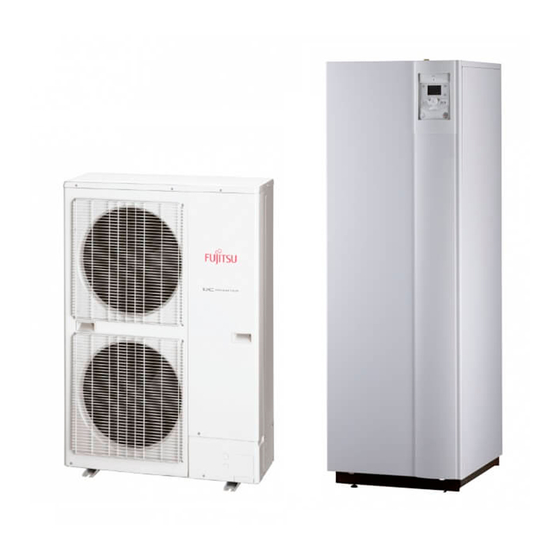
- Page 1 U0672825_2125_EN_2 29/04/2021 Outdoor unit WOYA060KLT WOYA080KLT WOYA100KLT Hydraulic unit WGYA050ML3 WGYA080ML3 WGYA100ML3 INSTALLATION Air/water heat pump split 2 services For professionals. To be kept by the user for future reference.
- Page 2 ■ Installation and maintenance rules ■ Containment of refrigeration circuits The appliance must be installed and maintained All refrigeration circuits are sensitive to dust and by an approved professional in accordance with moisture contamination. If any such pollutants current regulations and codes of practice. penetrate the refrigeration circuit, they can aff...
- Page 3 ■ Electrical connections • Connecting to screw terminals The use of ring, spade or blade terminals or Before performing any maintenance, make sure caps is prohibited. that all power supplies have been cut off . - Always select wire that complies with current •...
-
Page 4: Table Of Contents
This appliance must be installed by qualifi ed personnel holding a certifi cate of competence in the handling of refrigerants. Contents Description of the equipment Packing ....... . . 6 Operating Range . - Page 5 Maintenance of the installation Hydraulic checks ......70 Outdoor unit checks ..... . 70 Maintenance of the DHW tank .
-
Page 6: Description Of The Equipment
Description of the equipment Packing contents list Heat Pump Outdoor unit Hydraulic unit Model Reference Reference Waterstage Split Comfort Series 5 WOYA060KLT WGYA050ML3 Waterstage Split Comfort Series 6 WOYA060KLT WGYA080ML3 Waterstage Split Comfort Series 8 WOYA080KLT Waterstage Split Comfort Series 10 WOYA100KLT WGYA100ML3 ►... -
Page 7: General Characteristics
► General characteristics Model Rated heating performances (outdoor temp. / fl ow temp.) Heat output +7°C / +35°C - Underfl oor heating system 4.50 5.50 7.50 +7°C / +55°C - Radiator 4.50 5.50 7.00 Power absorbed +7°C / +35°C - Underfl oor heating system 0.949 1.18 1.69... - Page 8 ■ Outdoor unit Model 5 & 6 ■ Outdoor unit Model 8 ■ Outdoor unit Model 10 fi g. 1 - Dimensions in mm - 8 - Waterstage Split Comfort DHW Serie / INSTALLATION / 2125 - EN...
- Page 9 ■ Hydraulic unit Back view Side view Front view Space requirements of the hydraulic unit, see fi g. 19, page fi g. 2 - Dimensions in mm Back view Heating inlet Ø 26x34 1” male Heating outlet Ø 26x34 1” male Ø...
- Page 10 mCE (1 mbar = 10 mmCE = 100 Pa) PWM 100% PWM 75% fi g. 4 - Available hydraulic pressures and fl ow rates (models 5, 6 and 8) mCE (1 mbar = 10 mmCE = 100 Pa) PWM 100% PWM 75% fi...
- Page 11 10000 - Compressor - Discharge - Condensation - Expansion valve 1000 - Outdoor unit - Evaporator inlet -20 -10 0 10 20 30 40 50 60 70 80 90 100 110 120 130 Temperature °C fi g. 7 - Ohmic sensor values (Outdoor unit) Waterstage Split Comfort DHW Serie / INSTALLATION / 2125 - EN - 11 -...
-
Page 12: Description
► Description ■ Outdoor unit Model 5 & 6 ■ Outdoor unit Model 8 ■ Outdoor unit Model 10 12 13 3 Key : High performance and low noise impeller. Noise and thermally insulated "Inverter" compressor. Electrical motor with variable "Inverter" operation. 10. - Page 13 ■ Hydraulic unit Key : Electric control box. Drain valve. Sensors : Controller / User interface. 10. Safety valve. 20. Heat Pump return sensor. ON/OFF Switch. 11. Safety thermostat. 21. Domestic Hot Water sensor. Hydraulic unit circulation pump. 12. Pressure gauge. 22.
-
Page 14: Operating Principle
► Operating principle The heat pump transmits the energy contained in the ■ Control functions surrounding air into the dwelling to be heated. - The heating circuit's fl ow temperature is controlled by The heat pump consists of four main elements, in which the temperature control. - Page 15 ■ Domestic hot water (DHW) operating principle Two domestic hot water (DHW) temperatures can be If the contract signed with the energy provider includes set: comfort and reduced. a day/night tariff , the electrical backup is subject to the supplier’s power tariff and the comfort temperature may The default DHW program is set to the comfort only be reached at night.
-
Page 16: Installation
Installation ► Installation of refrigeration connections Bend the pipes into position and make holes for them through the fl oor or walls either with their protective caps in place or after brazing. Keep the protective caps in place or ends brazed until the appliance is commissioned. -
Page 17: Installation Of The Outdoor Unit
► Installation of the outdoor unit ▼ Installation precautions • Water may fl ow out of the outdoor unit when it is The outdoor unit must only be installed operating. Do not install the outdoor unit on a paved outside. If a shelter is required, it must have terrace;... - Page 18 ■ Model 10 100 mm 1000 mm 150 mm 1500 mm 200 mm 3000 mm 250 mm 3500 mm 300 mm M = 300 mm max 500 mm N = 500 mm max 600 mm fi g. 17 - Minimum installation clearances around the outdoor unit (model 10) - 18 - Waterstage Split Comfort DHW Serie / INSTALLATION / 2125 - EN...
- Page 19 • The surface on which the appliance is installed must: - Be permeable (soil, gravel, etc.). - Be perfectly fl at, - Support its weight easily. - Allow a solid fastening base, - Not transmit any vibration to the dwelling. Anti-vibratory blocks are available as an option.
-
Page 20: Installation Of The Hydraulic Unit
► Installation of the hydraulic unit Heat sources such as : - Open fl ame, - High temperature surface >700°C (fi lament), - Electrical circuit breaker >5kVA, Avoid using sources of heat inside the room where the heat pump is installed. If this is not possible, page 24 ▼... - Page 21 fi g. 20 - Open the front cover fi g. 21 - Removing the cover fi g. 22 - Floor fi xing Waterstage Split Comfort DHW Serie / INSTALLATION / 2125 - EN - 21 -...
- Page 22 ▼ Minimum room volume Modele (kW) Refrigeration connections Length In accordance with EN 378-1 -2017 standard 5, 6 (Refrigerating systems and heat pumps - Safety and R32 gas 1020 1630 environmental requirements), the ystem's hydraulic charge 15 m unit and all refrigeration connections passing through min room inhabited areas must comply with the minimum room volume...
- Page 23 200max fi g. 25 - Position of openings for ventilation Room volume (m Refrigerant Amount (g) Minimal section (S) of the opening (cm 970 500 1000 550 1100 600 No requirement 1170 600 1300 700 1400 750 1500 800 1600 850 1700 900 1800 950 1840 950...
- Page 24 ▼ With Heat sources Heat sources such as : - Open fl ame, - High temperature surface >700°C (fi lament), Modele (kW) - Electrical circuit breaker >5kVA, Refrigeration connections Length 5, 6 In accordance with IEC 60-335-2-40 standard, the hydraulic module of the heat pump as well as all the R32 gas 1020 1630...
- Page 25 Min. room surface Surface minimum fi g. 27 Voir figure xx pxx Surface mini Min. room surface Surface pièce (A) Room surface (A) Room surface (A) > Min. room surface ? Surface pièce (A) > Surface mini ? Module hydraulique installé Indoor unit in an Pas de recommandation No requirement...
-
Page 26: Refrigeration Connections
Refrigeration connections This appliance uses refrigerant R32. • Other remarks Comply with the legislation on handling of refrigerants. - After each maintenance operation on the refrigeration circuit and before fi nal connection, take care to put ► Rules and precautions the caps back in position to avoid any pollution of the refrigeration circuit. -
Page 27: Shaping The Refrigeration Pipes
► Shaping the refrigeration pipes ▼ Bending The refrigeration pipes must be shaped only on a fl are Flaring tool bending machine or with a bending spring in order to avoid any risk of crushing or breaking them. Remove the insulation material from the section of pipe to be bent. - Page 28 Model 5, 6 Model 8 Model 10 HP model liquid liquid liquid Outdoor unit connections 1/2" 1/4" 1/2" 1/4" Diameter (D1) 1/2" (D2) 1/4" (D1) 1/2" (D2) 1/4" (D1) 5/8 (D2) 3/8 Minimum length (L) Refrigeration Maximum length* (L) 20 m connections Maximum length** (L) 30 m...
-
Page 29: Checks And Connection
► ► Checks and connection Filling with gas The refrigeration circuit is very sensitive to dust ■ see "Filling the installation with gas", page 72 and humidity: check that the area around the connection is clean and dry before removing the Indicate on the label present on the outdoor plugs protecting the refrigeration connectors. - Page 30 ▼ Additional fi lling The amount needed to fi ll the outdoor units corresponds to the maximum distances between the outdoor unit and the hydraulic unit as defi ned here page 28. If the distances are greater, an additional amount of R32 is required. For each type of appliance, this additional amount depends on the distance between the outdoor unit and the hydraulic unit.
- Page 31 ▼ Recovering the refrigerant in the outdoor unit Before performing any maintenance, make sure that all power supplies have been cut off . Stored energy: after cutting off the power supplies, wait for 10 minutes before accessing the internal parts of the equipment. Perform the following procedures to collect the refrigerant.
-
Page 32: Hydraulic Connections
Hydraulic connections "Basic Hydraulic Layouts", page 74 ► Heating circuit ▼ Flushing the installation Before connecting the hydraulic unit to the installation, rinse out the heating system correctly to eliminate any particles that may aff ect the appliance's correct operation. Do not use solvents or aromatic hydrocarbons (petrol, paraffi... -
Page 33: Dhw Circuit
▼ Volume of the heating system You must maintain the minimum installation water volume. Install a buff er tank on the return from the heating circuit in case the volume is lower than this value. Where the system is fi tted with one or more thermostatic valves, you must ensure that this minimum water volume is able to circulate. -
Page 34: Electrical Connections
Electrical connections Before performing any maintenance, make sure that all power supplies have been cut off . Electrical installation must be performed in accordance with current regulations. The electrical diagram for the hydraulic unit is shown on fi g. 58, page Wireless remote control (option) Outside sensor Wireless room thermostat (option) -
Page 35: Cable Dimensions And Protection Rating
► Cable dimensions and protection rating These cable dimensions are provided for information purposes only and do not exempt the installer from checking that these dimensions match requirements and comply with current standards. ■ Outdoor Unit Power Supply Heat pump Electricity supply 230 V - 50 Hz Max. -
Page 36: Outdoor Unit
► Outdoor unit Access to connection terminals: • Model 5, 6 & 8 - Remove the cowl. • Model 10 - Remove the front panel. Avoid contact between cables and refrigeration valves / connections. Use cable clamps to prevent any power cables from being disconnected accidentally. -
Page 37: Hydraulic Unit
► Hydraulic unit ▼ Contract with Energy Supplier The heat pump can be set to operate within particular Access to connection terminals : types of energy contract, e.g. off -peak, PV (Photovoltaic). - Remove the front plate. In particular, domestic hot water (DHW) at the comfort - Open the power control box. -
Page 38: Outside Sensor
► Outside sensor ▼ Installing a room sensor The outside sensor is required for correct operation of ■ Room thermostat T55 (fi g. the heat pump. - Connect the sensor to the X86 connector of the heat Please see the fi tting instructions on the sensor’s pump’s regulator board using the connector provided packaging. - Page 39 Hydraulic unit Outdoor unit 1 2 3 1 2 3 L N green/yellow brown blue Interconnection between outdoor unit towards external and hydraulic unit component contact* Power supply for Power supply Electricity supply Electrical backup Domestic Hot Water single phase 230 V single phase 230 V 230 V fi...
-
Page 40: Controller Interface
Controller Interface ► User interface, central ambient unit (option) and ambient sensor (option) Auto Auto °C Ambient sensor (option) Central ambient unit (option) - 40 - Waterstage Split Comfort DHW Serie / INSTALLATION / 2125 - EN... - Page 41 Ref. Functions - Defi nition of the functions Selecting the DHW operation - Start: Production of DHW in function of the timer programme. - Stop: Production of the DHW stopped with antifreeze function of the domestic water active. Marche - Manual start button: Press the DHW button for 3 s (switches from "reduced"...
-
Page 42: Description Of The Display
► Description of the display Icons Defi nitions - Heating mode active with reference to the heating circuit. - Heating in comfort mode. Xxxxxxxxxxxxxxxxxxxxxxxxxxx - Heating in reduced mode. Xxxxxxxxxxxxxxxxxxxxxxxxxxx - Heating in "standby" mode Xxxxxxxxxxxxxxxxxxxxxxxxxxx (antifreeze). - Cooling mode active *. fi... -
Page 44: Temperature Control
Temperature control The heat pump's operation is subject to the temperature control. The heating circuit water temperature setpoint is adjusted according to the outdoor temperature. If there are thermostatic valves on the installation, these must be fully open or set higher than the normal temperature setpoint. - Page 45 Pente de la 2.75 Heating curve gradient courbe de chauffe ° C 2.25 Standard radiator Radiateur classique 1.75 Low temperature Radiateur BT radiator 1.25 (basse température) Application relève de chaudière With boiler connection Application PAC seule Heat pump application only Dynamic radiators Radiateur dynamique 0.75...
-
Page 46: Commissioning
Commissioning - Close the installation's main circuit breaker. During the regulator initialisation phase, the display shows all the symbols and then "Data, update" and then Upon initial start-up (or in winter), to preheat the "State heat pump". compressor, engage the installation's main circuit breaker (outdoor unit power supply) several - Make all the specifi... -
Page 47: Confi Guring Room Thermostat (Wireless)(Option)
► Confi guring room thermostat (wireless)(option) - Hold down presence key; room To confi gure the room thermostat and connect it to the appropriate heating zone: thermostat displays "P1" and a fl ashing number. 1: Automatic recording: a correction of the setting - Hold down the presence key for more than 3 seconds. -
Page 48: Controller Menu
Controller Menu ▼ General ▼ Setting parameters Only the parameters accessible at the levels: - Selecting the desired level. U - end user. - Scroll the list of menus. I - Commissioning - Selecting the desired menu. S - Engineering. - Scroll the function lines. -
Page 49: List Of Function Lines
► List of function lines Setting range Setting Basic Line Function or display increment setting Time of day and date Hours / Minutes 00:00... 23:59 --:-- Day / Month 01.01... 31.12 --.-- Year 1900... 2099 ---- Start of Summer time (Day / Month) 01.01... - Page 50 Setting range Setting Basic Line Function or display increment setting Time program heating / cooling, circuit 2 Only with the 2 circuit kit option. Pre-selection (Day / Week) Mon-Sun, Mon-Fri, Sat-Sun, Mon-Sun Monday, Tuesday, … phase On (start) 00:00... --:-- 10 min 6:00 phase Off...
- Page 51 Setting range Setting Basic Line Function or display increment setting Heating adjustment, circuit 1 Comfort setpoint Reduced setpoint… 0.5 °C 20 °C Comfort setpoint maximum Reduced setpoint Frost protection setpoint… 0.5 °C 19 °C Comfort setpoint Frost protection setpoint 4 °C… Reduced setpoint 0.5 °C 8 °C Comfort setpoint maximum...
- Page 52 Setting range Setting Basic Line Function or display increment setting Floor curing function (fi g. Off - Off : Early interruption of the current programme, programme inactive. - Operational heating. - Heating ready for occupation. - Operational heating + ready heating. - Ready heating + operational heating.
- Page 53 Setting range Setting Basic Line Function or display increment setting Room infl uence --, 1... 100 % 80 % If the installation is fi tted with a room thermostat: This function enables you to choose the ambient temperature's infl uence on the setting. If no value is entered, the setting is made based on the temperature control.
- Page 54 Setting range Setting Basic Line Function or display increment setting 1150 Floor curing function (fi g. 51, page Off - Off : Early interruption of the current programme, programme inactive. - Operational heating. - Heating ready for occupation. - Operational heating + ready heating. - Ready heating + operational heating.
- Page 55 Setting range Setting Basic Line Function or display increment setting Domestic hot water 1600 Operating mode Off , On, Eco 1610 Nominal setpoint Reduced setpoint (line 1612)… 55 °C 65 °C The backup electrical system is required to reach this level. 1612 Reduced setting 8 °C...
- Page 56 Setting range Setting Basic Line Function or display increment setting Heat pump (HP) 2779 Pump speed max condenser pump cooling mode 70... 100 % 100 % 2793 Pump speed max condenser pump 70... 100 % 100 % 2803 Overrun time cond pump 8...
- Page 57 Setting range Setting Basic Line Function or display increment setting 3145 Energy brought in heating 4 (N - 4) 3146 Energy brought in DHW 4 3147 Energy brought in cooling 4 3149 --> 3151 : Not used 3152 Energy brought in heating 5 (N - 5) 3153 Energy brought in DHW 5 3154...
- Page 58 Setting range Setting Basic Line Function or display increment setting Additional generator (Boiler connection) 3692 With DHW charging Locked, Substitute, Substitute Complement, Instantly - DHW Instantly : When DHW request, the HP and the boiler are put into operation. The HP will stop when the primary return temperature is over 55 °C.
- Page 59 Setting range Setting Basic Line Function or display increment setting 5813 Output el imm heater K26 0.1-...99 3 kW Without electrical backup = 0 ; Single phase electrical backup 3 kW = 0 ; Single phase electrical backup 6 kW (Factory setting) = 3 ; 3-phase electrical backup = 0 5950 Function input H1 (Connector X86, terminals B1 &...
- Page 60 Setting range Setting Basic Line Function or display increment setting 6098 Readjustm collector sensor -20... 20 °C 0.1 °C 0 °C 6100 Readjustm outdoor sensor -3... 3 °C 0.1 °C 0 °C 6117 Central setp compensation 1... 100°C 1 °C 5 °C 6120 Frost protection plant...
- Page 61 Setting range Setting Basic Line Function or display increment setting Inputs / outputs test 7700 Relay test No test This consists of instructing the regulator's relays one by one and checking their outputs. This enables you to check that the relays are working and that the cabling is correct (Check that each appliance in the installation is operating correctly / See "Designation of terminals of the control board", page 79).
- Page 62 Setting range Setting Basic Line Function or display increment setting Generator diagnosis 8400 Compressor 1 Off , On Off 8402 Electrical resistance fl ow 1 Off , On Off 8403 Electrical resistance fl ow 2 Off , On Off 8406 Condenser pump Off...
- Page 63 Setting range Setting Basic Line Function or display increment setting 8756 Cooling fl ow temperature 1 0... 140 °C Cooling fl ow temperature setpoint 1 8820 DHW pump Off , On Off 8821 El imm heater DHW Off , On Off...
-
Page 64: Information Display
► Information display Various data can be displayed by pressing the - Various data (see below). button. Designation Line Depending on the type of unit, confi guration and Floor drying current setpoint. operating state, some of the info lines listed below may Current drying day. -
Page 66: Fault Diagnosis
Fault Diagnosis Depending on whether the fault comes from the outdoor unit or the hydraulic unit, the fault may be indicated by the digital display or the LED on the interface cards. ► Faults in the Hydraulic Unit Faults or breakdowns on the hydraulic unit are indicated by the display on the user interface. The display shows the symbol. -
Page 67: Pwm Circulator Signals
► PWM circulator signals Off The pump does not work, no electrical power. Green On The pump works normally. Circulation pump operation in "alert" mode Green/Red blink (under unusual conditions such as: dry running, motor overload due to impurities in the water, etc.). Operating error due to a persistent external fault Red blink (abnormal voltage/current, external pump blockage, reverse fl... -
Page 68: Faults In The Outdoor Unit
► Faults in the outdoor unit ■ Hydraulic unit: Flashing of the diode visible on the interface board. Interface Board Error Error designation (models 5, 6 and 8) Error designation (model 10) Green Serial communication error Combination Error UART communications error Hydraulic unit heat-exchange thermistor error Outdoor unit main PCB error Inverter error... - Page 69 ▼ Outdoor Unit : model 10 When an error occurs: POWER PUMP PEAK - The LED "ERROR" (2) blinks. ERROR DOWN NOISE MODE - Press once on the switch "ENTER" (S132). - The LED blinks several times depending on the error's type (see below).
-
Page 70: Maintenance Of The Installation
Maintenance of the installation Before performing any maintenance, make sure that all power supplies have been cut off . Stored energy: after cutting off the power supplies, wait for 10 minutes before accessing the internal parts of the equipment. ► Hydraulic checks If frequent refi... -
Page 71: Other Maintenance
Other maintenance ► Emptying the hydraulic unit Return from - Remove the front panel from the HP. the heating circuit - Place the distribution valve in the middle position. Valve motor - Open the drain valve (ref. 5). Valve - Open the hydraulic unit's manual bleeder valve (ref. 6). - Open the installation’s bleeder valve(s). -
Page 72: Appendix
Appendix ► Filling the installation with gas This operation is reserved for installers familiar with the legislation for handling refrigerants. Creating a vacuum with a calibrated vacuum pump is essential (see APPENDIX 1). Never use equipment used previously with any refrigerant other than a HFC. Only remove the refrigeration circuit caps when performing the refrigeration connections. - Page 73 ▼ Seal test ▼ Creating a vacuum - Remove the protective plug (B) from the fi lling hole The triple evacuation method (APPENDIX 2) (Schrader) in the gas valve (large diameter). is strongly recommended for any installation - Connect the high pressure hose from the Manifold to and especially when the outdoor temperature the fi...
-
Page 74: Basic Hydraulic Layouts
► Basic Hydraulic Layouts ■ 1 heating circuit - 74 - Waterstage Split Comfort DHW Serie / INSTALLATION / 2125 - EN... - Page 75 ■ 2 heating circuits Waterstage Split Comfort DHW Serie / INSTALLATION / 2125 - EN - 75 -...
-
Page 76: Electrical Cabling Plans
► Electrical Cabling Plans Before performing any maintenance, make sure that all power supplies have been cut off . Stored energy: after cutting off the power supplies, wait for 10 minutes before accessing the internal parts of the equipment. ▼ Outdoor unit Vanne 4 voies 4-way valve Electronic expansion... - Page 77 Colour codes BK Black BN Brown BU Blue GN Green GY Grey Capteur Pressure switch Ventilateur Fan motor OG Orange de pression RD Red VT Violet WH White YE Yellow Compresseur Compressor R(U) T(W) S(V) Printed Circuit Board Carte inverter (Inverter) Printed Circuit Board Carte de régulation...
- Page 78 ▼ Hydraulic unit Connections on the heat pump controller, accessories and options (see fi g. 45, page Connection to terminal blocks and power relay (see fi g. 44, page fi g. 58 - Electrical wiring of hydraulic unit (excluding connections made by installer) - 78 - Waterstage Split Comfort DHW Serie / INSTALLATION / 2125 - EN...
-
Page 79: Designation Of Terminals Of The Control Board
► Designation of terminals of the control board ► Designation of terminals on the expansion card Waterstage Split Comfort DHW Serie / INSTALLATION / 2125 - EN - 79 -... -
Page 80: Quick-Start Procedure
Quick-start procedure Before switching on the hydraulic unit: • Check the electric wiring. • Check the refrigeration circuit and make sure the it has been gassed. • Check the hydraulic circuit's pressure (1 to 2 bar), check that the heat pump has been bled, along with the rest of the installation. - Page 81 ▼ Starting-up Not compliant Quick Start Procedure (see chapter " Commissioning", page 46 " Controller Menu", page Close the installation's main circuit breaker (outdoor unit power supply) 6 hours before testing => Preheating of the compressor. Press the On/Off Switch => Initialisation takes several seconds. Operation of the heating circulation pump.
-
Page 82: Settings Sheet
► Settings sheet Setting Description Set to. Menus Setting Description Set to. Menus Preliminary settings Boiler backup (with "Boiler" kit option) language operator 3700 OT.switch-on authoris. addit. gen. section 3705 swith-off delay addit. gen. hour / minutes time & date Miscellaneous day / month time &... -
Page 83: Commissioning Technical Datasheet
► Commissioning technical datasheet Site Installer Serial No. Serial No. Outdoor unit Hydraulic unit Model Model Refrigerant type Refrigerant load Checks Operating voltage & current on outdoor unit Compliance with positioning distances Condensate evacuation correct Electric connections / connections tightness No GAS leaks (unit ID No.: Icomp Installation refrigeration connection correct (length... - Page 84 Instructions for the end user Explain to the user how his installation operates, in particular the functions of the room sensor and the programmes accessible to them via the user interface. Emphasise that a heated fl oor has signifi cant inertia and that therefore any adjustments must be made gradually.
- Page 85 This unit is identifi ed by this symbol. It means that all electrical and electronic products must not be included in household waste. A specifi c recycling system for this type of product has been set up in European Union countries (*), Norway, Iceland and Liechtenstein. Do not try to dismantle this product yourself.
- Page 86 Internal production control plus supervised pressure equipment checks at random intervals(Module A2) TÜV Rheinland Industrie Service GmbH, Am Grauen Stein, D-51105 Köln, Germany 0035 01 202 TH/Ü-170006 FUJITSU GENERAL (EURO) GmbH Fritz-Vomfelde-Straße 26-32, 40547 Düsseldorf, Germany Place of issue Japan Date of issue 1.
- Page 87 English [En] EU DECLARATION OF CONFORMITY Manufacturer [I] declares under its sole responsibility that the products [II] are in conformity with the require- ments of the EU Directives, Regulations and Harmonised standards [III]. German [De] EU-KONFORMITÄTSERKLÄRUNG Der Hersteller [I] erklärt in alleiniger Verantwortung, dass die Produkte [II] allen Anforderungen der EU-Richtlini- en, Verordnungen und harmonisierten Normen [III] entsprechen.
- Page 88 - EN 12102-1 standard: determination of the sound power level Keymark Certifi cation : 012-C700097 - FUJITSU Waterstage Split Comfort Series Integrated DHW 5 012-C700099 - FUJITSU Waterstage Split Comfort Series Integrated DHW 6 012-C700101 - FUJITSU Waterstage Split Comfort Series Integrated DHW 8...