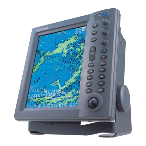
Furuno MARINERADAR FR-8122 Installation Manual
Furuno marine radar user manual
Hide thumbs
Also See for MARINERADAR FR-8122:
- Installation manual (52 pages) ,
- Operator's manual (129 pages) ,
- Specifications (2 pages)
Table of Contents
Advertisement
MARINE RADAR FR-8062/8122/8252
SYSTEM CONFIGURATION ............................................................................................................... ii
EQUIPMENT LISTS..............................................................................................................................iv
1. MOUNTING................................................................................................................................. 1-1
1.1 Antenna Unit.......................................................................................................................... 1-1
1.2 Display Unit ......................................................................................................................... 1-12
1.3 Power Supply Unit............................................................................................................... 1-15
2. WIRING....................................................................................................................................... 2-1
2.1 Standard Wiring..................................................................................................................... 2-1
2.2 Wiring the Power Supply Unit ............................................................................................... 2-2
2.3 Port for External Devices ...................................................................................................... 2-4
3. SETTING UP THE EQUIPMENT ................................................................................................ 3-1
3.1 Setting Language .................................................................................................................. 3-1
3.2 Opening the Installation Menu .............................................................................................. 3-2
4. OPTIONAL EQUIPMENT............................................................................................................ 4-1
4.1 ARP Kit ARP-11..................................................................................................................... 4-1
4.2 External Monitor .................................................................................................................... 4-3
4.3 Remote Display..................................................................................................................... 4-5
4.4 External Buzzer..................................................................................................................... 4-7
PACKING LIST, INSTALLATION MATERIALS, SPARE PARTS ..................................................... A-1
OUTLINE DRAWINGS......................................................................................................................D-1
INTERCONNECTION DIAGRAMS................................................................................................... S-1
All brand and product names are trademarks, registered trademarks or service marks of their respective holders.
Installation Manual
www.furuno.co.jp
Advertisement
Table of Contents

Related Manuals for Furuno MARINERADAR FR-8122


Summary of Contents for Furuno MARINERADAR FR-8122
-
Page 1: Table Of Contents
4.3 Remote Display... 4-5 4.4 External Buzzer... 4-7 PACKING LIST, INSTALLATION MATERIALS, SPARE PARTS ... A-1 OUTLINE DRAWINGS...D-1 INTERCONNECTION DIAGRAMS... S-1 All brand and product names are trademarks, registered trademarks or service marks of their respective holders. Installation Manual www.furuno.co.jp... - Page 2 : +81-(0)798-65-4200 Printed in Japan All rights reserved. Pub. No. IME-35390-G (YOSH ) FR-8062/8122/8252 The paper used in this manual is elemental chlorine free. ・FURUNO Authorized Distributor/Dealer A : SEP G : MAR . 02, 2011 *00015331816* *00015331816* *00015331816* *00015331816*...
- Page 3 SAFETY INSTRUCTIONS WARNING Do not open the equipment unless totally familiar with electrical circuits and service manual. Only qualified personnel ELECTRICAL should work inside the SHOCK equipment. HAZARD Wear a safety belt and hard hat when working on the antenna unit. Serious injury or death can result if someone falls from the radar mast.
-
Page 4: System Configuration
SYSTEM CONFIGURATIONS FR-8062/8122 Auto Plotter ARP-11 (built in display unit) 100/110/ AC-DC Power Supply 115/220/ PR-240 230 VAC, 1 φ 12-24 VDC Remote Display Commercial Monitor (SVGA or better) Category of units Antenna unit: Exposed to weather All other units: Protected from weather ANTENNA UNIT RSB-0073-085-XN12A/XN13A: FR-8062 RSB-0073-086-XN12A/XN13A: FR-8122... - Page 5 FR-8252 Auto Plotter ARP-11 (built in display unit) 100/110/ AC-DC Power Supply 115/220/ PR-240 230 VAC, 1 φ 12-24 VDC Remote Display Commercial Monitor (SVGA or better) Category of units Antenna unit: Exposed to weather All other units: Protected from weather ANTENNA UNIT RSB-0073-087-XN12A/XN13A POWER SUPPLY UNIT...
-
Page 6: Equipment Lists
EQUIPMENT LISTS Standard Supply Name XN12A-RSB-0073-085 XN13A-RSB-0073-085 XN12A-RSB-0073-086 Antenna unit XN13A-RSB-0073-086 XN12A-RSB-0073-087 XN13A-RSB-0073-087 Display unit RDP-150 Power supply unit PSU-008 CP03-30801 CP03-30700 CP03-30710 CP03-30720 Installation CP03-30730 materials CP03-30500 CP03-30510 CP03-30520 CP03-30530 CP03-30900 Spare parts SP03-15401 Type Code No. 008-552-960 000-090-471 000-090-472 000-090-473 000-090-474... - Page 7 Optional Supply Name External buzzer OP03-136 AC-DC Power Supply PR-240 MJ-A7SPF0007-0 MJ-A6SPF0003-0 MJ-A6SPF0007-1 Cable assy. MJ-B24LPF0008- MJ-B24LPF0008- MJ-B24LPF0008- Auto plotter ARP-11 Installation materials CP03-31001 RGB kit OP03-195 Remote controller RCU-019 Type Code No. 000-086-443 000-144-418-10 000-154-054-10 000-159-695-10 000-145-125 000-145-126 000-145-127 008-523-050 008-556-830 008-553-110...
- Page 8 This page intentionally left blank.
-
Page 9: Mounting
1. MOUNTING 1.1 Antenna Unit Mounting considerations • The antenna unit is generally installed either on top of the wheelhouse or on the radar mast on a suitable platform. Locate the antenna unit where there is a good all-round view. Any obstruction will cause shadow and blind sectors. - Page 10 1. MOUNTING Mounting procedure Referring to the outline drawing at the back of this manual, drill five holes in the mounting platform: four holes of 15 mm diameter for fixing the antenna unit and one hole of 25-30 mm diameter for the signal cable. Fastening the radiator to the radiator bracket For your reference, the antenna installation materials list appears in the packing list at the back of this manual.
- Page 11 Mounting the antenna unit The antenna unit can be mounted using the fixing holes on the outside (200x200 mm) or inside (140x150 mm) the antenna unit. Using outside fixing holes of the antenna housing Use the hex head bolts (supplied) to mount the antenna unit as below. 1.
- Page 12 1. MOUNTING 3. Insert four hex bolts (M12x60, supplied) and seal washers (Ф30, supplied) from the top of the antenna housing, as shown below. 4. Pass flat washers (M12, supplied), spring washers (M12, supplied) and nuts (M12, supplied) onto hex bolts. Fasten by tightening nuts. Do not fasten by tightening the hex bolts;...
- Page 13 8. Coat ground terminal and ground point with silicone sealant as shown below. Ground wire Silicone sealant Ground wire GROUND TERMINAL How to coat ground point and ground terminal with silicone sealant Hex bolt Flat washer Flat washer Spring washer Hex nut GROUND POINT...
- Page 14 1. MOUNTING Using inside fixing holes of the antenna housing This method requires removal of the RF unit in the antenna unit to access inside fixing holes. Use hex head bolts, flat washers, spring washers and nuts (local supply) to mount the antenna unit, confirming length of bolts.
- Page 15 1. MOUNTING Connecting the signal cable Only the signal cable runs from the display unit (power supply unit in case of FR-8252) to the antenna unit. In order to minimize the chance of picking up electrical interference, avoid where possible routing the signal cable near other onboard electrical equipment. Also, avoid running the cable in parallel with power cables.
- Page 16 1. MOUNTING • Connecting the signal cable 1. Open the antenna cover by loosening four bolts, and then fix the stay. Antenna unit chassis, cover opened 2. Unfasten the cable gland assembly (plate, gasket, flat washer). The plate may be discarded.
- Page 17 5. Fasten the shielded part of the signal cable with shield clamp (installation material) as shown below. How to fix signal cable in cable gland 6. Unfasten four screws to remove the RTB board cover. 7. Connect the plugs of the signal cable to the RTB board. FR-8062, FR-8122: J821, J823, J824, J822 FR-8252: J821, J823, J824, J820...
- Page 18 1. MOUNTING 9. Attach three EMI cores to the signal cable as shown below. EMI Core RFC-13 (2 pcs) EMI Core RFC-H13 (1 pc) Antenna unit chassis, cover opened 10. Fix the signal cable with the cable clamp as follows. a) Dismount the cable clamp plate and remove clamp and gasket.
- Page 19 b) Run the signal cable as shown below. c) Fix the signal cable with cable clamp as shown below. 11. Release the stay and close the cover. Loosely fasten the antenna bolts; you will have to make some adjustments inside after completion of wiring. Note: When closing the cover, set the gaskets to grooves in the bottom chassis, then tighten bolts.
-
Page 20: Display Unit
1. MOUNTING 1.2 Display Unit The display unit can be mounted on a tabletop, on the overhead or flush mounted in a console or panel. Mounting considerations When selecting a mounting location for the display unit, keep the following in mind: •... - Page 21 1. MOUNTING Mounting procedure Tabletop mounting Follow the procedure below to mount the display unit on a tabletop. 1. Fix the hanger by using four self-tapping screws (5x20). 2. Screw knob bolts in display unit, set it to the hanger, and tighten the knob bolts. Fix with four self-tapping screws.
- Page 22 1. MOUNTING Flush mounting 1. Prepare a cutout in the mounting location whose dimensions are as shown below. 2. Detach two rubber cushions from the display unit. 3. Insert the flush mounting sponge and four threaded rods from the rear side of the display unit, and then set the display unit to the mounting location.
-
Page 23: Power Supply Unit
1.3 Power Supply Unit A power supply unit is shipped with the FR-8252, because of its high power consumption. The power supply unit can be installed almost anywhere provided the location is dry, well-ventilated, sufficient maintenance space is provided and is installed within 5 m (cable length) from the display unit. - Page 24 1. MOUNTING This page is intentionally left blank. 1-16...
-
Page 25: Wiring
2. WIRING 2.1 Standard Wiring FR-8062/8122 MJ-B24LPF0012-xxx (10/15/20/30m) MJ-A7SPF0007-050C NMEA device MJ-A7SPF0007-050C NMEA device MJ-A6SPF0003-050C MJ-A6SPF0007-100C Heading sensor MJ-A7SPF0007-050C External buzzer, Antenna unit RSB-0073 MJ-B24LPF0011-050 (5m) 12-24 VDC FR-8252 Antenna unit RSB-0073 RW-9771 (10/15/20/30m) Power supply unit PSU-008 VL3P-VV-S2X2C-AA050 (5m) 12-24 VDC Display unit RDP-150... -
Page 26: Wiring The Power Supply Unit
2. WIRING 2.2 Wiring the Power Supply Unit Cabling 1. Unfasten four screws to remove the cable clamp. 2. Unfasten four screws to remove the cover. 3. Attach the connectors of three cables as shown in the figure below. POWER Board 03P9419 J1 3P VL3P-VV-S2X 2C-AA050... - Page 27 Jumper block, slide switch setting The jumper block JP1 and slide switch S112 on the PWR board (03P9419) must be set according to radar model. Open the unit, locate JP1 and S112 and set them as below. Jumper block, slide switch Function S112 Power requirement, replacement of fuses Power requirement...
-
Page 28: Port For External Devices
2. WIRING 2.3 Port for External Devices External equipments can be connected here as shown below. NMEA1(7P) NMEA sentence NMEA sentence device device This equipment can receive the following NMEA 0183 format sentences from other equipment. You will need the optional NMEA cable to connect with external equipment. •... -
Page 29: Setting Up The Equipment
3. SETTING UP THE EQUIPMENT 3.1 Setting Language At the first power application after installation, choose a language as follows. 1. Press /BRILL key to turn the power on. “Now Initializing…” appears and after a while the window below appears. 2. -
Page 30: Opening The Installation Menu
3. SETTING UP THE EQUIPMENT 3.2 Opening the Installation Menu After you have installed the equipment, set it up as follows. 1. Press the MENU key. The main menu appears on the screen. 2. Rotate the trackball downward to choose Installation. The installation menu appears in gray to right side of the screen. - Page 31 View Position: Choose the operating position for this radar among Left, Left-Center, Center, Right-Center and Right to view echo colors correctly. The default setting is Center. Left: When operating this radar at the left side. Left-Center: When operating this radar at the left-center side. Center: When operating this radar at center position.
- Page 32 3. SETTING UP THE EQUIPMENT 2. Transmit the radar at 0.25 nm range and measure the bearing of that target relative to ship’s heading with an EBL. 3. Open the Installation menu, and choose Heading Adjust. 4. Press the ENTER key to show the HEADING ADJUST window. 5.
- Page 33 Manual Timing Adjust This adjustment ensures proper radar performance, especially on short ranges. The radar measures the time required for a transmitted echo to travel to the target and return to the source. The received echo appears on the display based on this time. Thus, at the instant the transmitter is fired, the sweep should start from the center of the display (sometimes called sweep origin.) A trigger pulse generated in the display unit goes to the antenna unit through the signal...
- Page 34 3. SETTING UP THE EQUIPMENT Manual MBS Adjust Main bang (black hole), which appears at the display center on short ranges, can be suppressed as follows. 1. Transmit the radar on the short range. 2. Open the Installation menu and choose Manual MBS Adjust. 3.
-
Page 35: Optional Equipment
4. OPTIONAL EQUIPMENT 4.1 ARP Kit ARP-11 The ARP kit provides automatic radar plotter functions to this radar. Necessary parts Name: ARP kit Type: ARP-11 Code no.: 008-523-050 Name ARP Board 18P9014B Pan head screw M3x6 C2700W SQ-9 Spacer* SQ-15 Spring washer* M3 C5191W 1. - Page 36 4. OPTIONAL EQUIPMENT 4. Mount the ARP board, mating with connectors and fixing it with four screws at the location as shown in the figure below. ARP board 5. Remount 03P9415 and 03P9413 at original position and display cover. Note: After connecting the harness to J601 on 03P9413, bend the harness so that it does not touch the parts on ARP board.
-
Page 37: External Monitor
4.2 External Monitor You can display the radar image on an external monitor which accepts industrial standard VGA input using the optional RGB kit OP03-195. Supply monitor and interconnection cable (with HD-15P connectors of male, three rows of 15 pins) locally. Necessary parts for external monitor Name: RGB kit... - Page 38 4. OPTIONAL EQUIPMENT 6. Detach LCD panel from the above assembly. Be sure to disconnect the connector and flat cables. 7. Connect the cable assy. 15SDS/XHP10-005 to the rear side of the RGB board. 8. Fix the shield wire of the cable assy. with a screw used to fix the RGB board. 9.
-
Page 39: Remote Display
4.3 Remote Display The FURUNO Display Unit FMD-811, MODEL1832 or GD-280/380, etc. can be connected to this radar as a sub display. The display unit RDP-150 also can be used as a sub display. To interconnect them, use optional cable MJ-B24LPF0008-100/200/300 (see page iv). Also, the EMI core (option) should be attached to the remote display cable to prevent noise. - Page 40 4. OPTIONAL EQUIPMENT 7. Fix the signal cable to the spacer of the FIL board with a cable tie CV-150N. Fix the cable to the spacer of FIL board with cable-tie. 8. Reassemble the display unit.
-
Page 41: External Buzzer
4.4 External Buzzer The optional external buzzer provides a louder alert when an alarm is violated. External buzzer Type: OP03-136 Code no.: 000-086-443 Further, you need the optional cable assy. MJ-A7SPF0007-050C (w/7P connector, 5 m, code no. 000-154-028-10). 1. Attach the MJ-A7SPF0007-050C cable assy. (option) to the PC/EXT-BUZZER port at the rear of the display unit. - Page 42 4. OPTIONAL EQUIPMENT This page is intentionally left blank.