Furuno FR-8062 Operator's Manual
Furuno marine radar user manual
Hide thumbs
Also See for FR-8062:
- Operator's manual (105 pages) ,
- Specifications (2 pages) ,
- Installation manual (56 pages)
Table of Contents
Advertisement
Quick Links
Advertisement
Table of Contents
Troubleshooting

Related Manuals for Furuno FR-8062


Summary of Contents for Furuno FR-8062
- Page 1 MARINE RADAR FR-8062, FR-8122, FR-8252...
- Page 2 Pub. No. OME-35390 ( ( DAMI DAMI ) ) FR-8062/8122/8252 FR-8062/8122/8252 The paper used in this manual is elemental chlorine free. FURUNO Authorized Distributor/Dealer FURUNO Authorized Distributor/Dealer FIRST EDITION : FIRST EDITION : SEP. SEP. 2005 2005 : : OCT.
- Page 3 The screen you see depends on your system configuration and equip- ment settings. • FURUNO will assume no responsibility for the damage caused by improper use or modifica- tion of the equipment by an unauthorized agent or a third party.
- Page 4 SAFETY INSTRUCTIONS SAFETY INSTRUCTIONS Radio Frequency Radiation Hazard The radar antenna emits electromagnetic radio frequency (RF) energy which can be harmful, particularly to your eyes. Never look directly into the antenna aperture from a close distance while the radar is in operation or expose yourself to the transmitting antenna at a close distance.
- Page 5 WARNING ELECTRICAL SHOCK HAZARD Do not open the equipment. Only qualified personnel should work inside the equipment. Turn off the radar power switch before servicing the antenna unit. Post a warn- ing sign near the switch indicating it should not be turned on while the antenna unit is being serviced.
- Page 6 Check all available navigation aids to determine target movement. WARNING LABELS Warning labels are attached to the equipment. Do not remove any label. If a label is missing or damaged, contact a FURUNO agent or dealer about replacement. DISPLAY UNIT WARNING Name: To avoid electrical shock, do not remove cover.
-
Page 7: Table Of Contents
TABLE OF CONTENTS FOREWORD ... ix SYSTEM CONFIGURATION ... xi 1. OPERATIONAL OVERVIEW...1-1 Controls ...1-1 1.1.1 Display unit ...1-1 1.1.2 Remote controller ...1-2 Turning the Radar On/Off, Transmitting ...1-3 Display Indications...1-4 Adjusting Display Brilliance, Panel Dimmer...1-5 Menu Overview...1-5 Tuning...1-7 Presentation Modes...1-8 1.7.1 Choosing presentation mode...1-8 1.7.2... - Page 8 TABLE OF CONTENTS 1.22 Zoom ... 1-27 1.22.1 How to zoom ... 1-27 1.22.2 Zoom mode ... 1-28 1.23 Echo Stretch... 1-29 1.24 Echo Averaging ... 1-30 1.25 Target Trails ... 1-31 1.25.1 Starting, stopping trails... 1-31 1.25.2 Trail mode ... 1-32 1.25.3 Trail gradation ...
- Page 9 2. RADAR OBSERVATION ...2-1 General...2-1 2.1.1 Minimum and maximum ranges ...2-1 2.1.2 Radar resolution ...2-2 2.1.3 Bearing accuracy ...2-2 2.1.4 Range measurement ...2-2 False Echoes...2-3 2.2.1 Multiple echoes ...2-3 2.2.2 Sidelobe echoes ...2-3 2.2.3 Virtual image ...2-4 2.2.4 Shadow sector ...2-4 SART (Search and Rescue Transponder)...2-5 2.3.1 SART description...2-5...
- Page 10 TABLE OF CONTENTS 5. GPS OPERATION ... 5-1 Navigator Type... 5-1 Datum... 5-2 WAAS Setup ... 5-2 Satellite Monitor ... 5-3 Weather Information... 5-4 GPS Sensor Installation Position Offset... 5-5 Cold Start ... 5-6 6. MAINTENANCE & TROUBLESHOOTING ... 6-1 Preventive Maintenance...
-
Page 11: Foreword
A Word to the Owner of the FR-8xx2 Marine Radar FURUNO Electric Company thanks you for purchasing the FR-8xx2 series Color LCD Marine Radar. We are confident you will discover why the FURUNO name has become synonymous with quality and reliability. - Page 12 FOREWORD Radar Specifications and Function Availability This radar series is available in three specification types (river, sea and IEC), and function avail- ability depends on specification type. The table below shows specification type and function avail- ability. River: For river-going vessels Sea: For sea-going vessels IEC: IEC compliant radar Item...
-
Page 13: System Configuration
SYSTEM CONFIGURATION FR-8252 Auto Plotter ARP-11 (built into display unit) Rectifier 100/110/ RU-3423 115/220/ φ 230 VAC, 1 12-24 VDC Remote Display Commercial Monitor (SVGA or better) Category of units Antenna unit: Exposed to weather All other units: Protected from weather ANTENNA UNIT RSB-0073-087-XN12A/XN13A POWER SUPPLY UNIT... - Page 14 SYSTEM CONFIGURATION FR-8122, FR-8062 Auto Plotter ARP-11 (built into display unit) Rectifier 100/110/ RU-3423 115/220/ φ 230 VAC, 1 12-24 VDC Remote Display Commercial Monitor (SVGA or better) Category of units Antenna unit: Exposed to weather All other units: Protected from weather ANTENNA UNIT RSB-0073-085-XN12A/XN13A: FR-8062 RSB-0073-086-XN12A/XN13A: FR-8122...
-
Page 15: Operational Overview
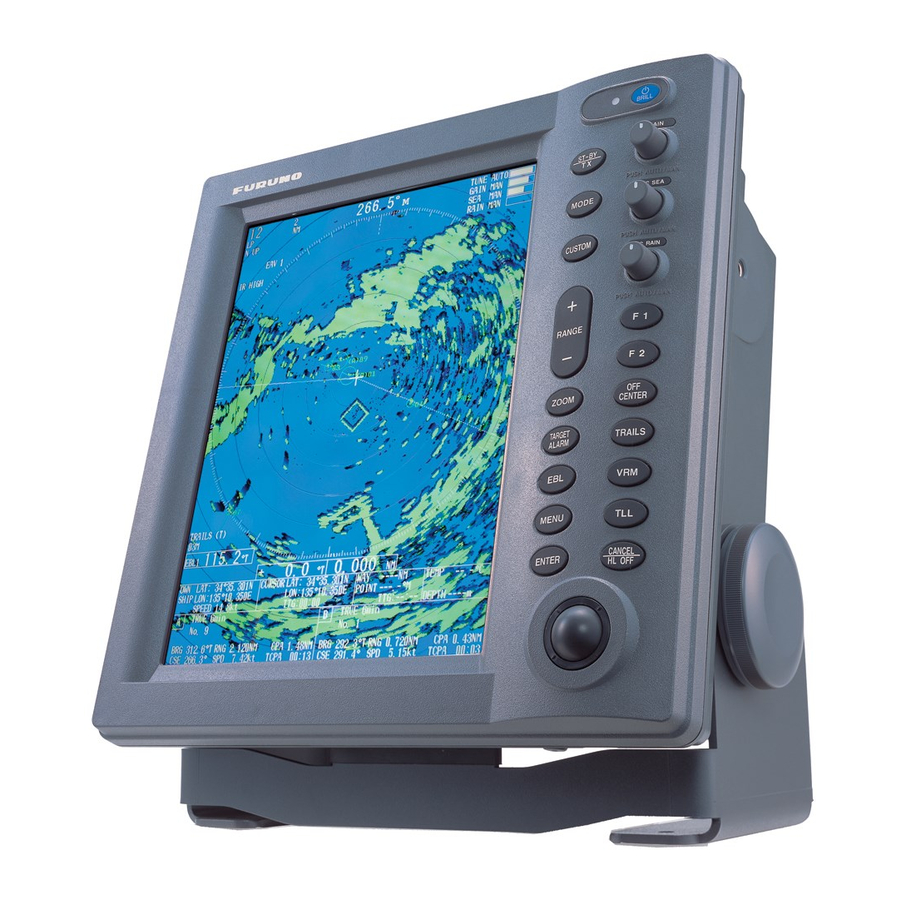
OPERATIONAL OVERVIEW Controls 1.1.1 Display unit This radar is operated with the controls of the display unit (and the remote controller), which includes 18 keys that are labeled with their functions, three knob controls and a trackball. When you correctly execute an operation, the unit generates a beep. Invalid operation causes the unit to emit several beeps. -
Page 16: Remote Controller
1. OPERATIONAL OVERVIEW 1.1.2 Remote controller The optional remote controller provides armchair control over transmit, standby, range and display offcentering (30% in stern direction). STBY Offcenters display. Toggles STBY/TX. CENTER Chooses range. RANGE Remote controller... -
Page 17: Turning The Radar On/Off, Transmitting
ROM: OK Program No. 0359226-xx.xx FURUNO ELECTRIC CO., LTD. After the tests are completed, the bearing scale and a digital timer appear. The digital timer counts down the time remaining to warm up the magnetron, which transmits the radar pulses. This warm- up takes 180 sec. -
Page 18: Display Indications
1. OPERATIONAL OVERVIEW Display Indications Presentation mode Auto adjustment of rain and sea clutters Range 0.75 Pulse length OFFCENTER(M) H UP Custom setting name HARBOR A/C AUTO Echo stretch (ES), ES 1 EAV1 NR LOW Echo averaging (EAV) IR LOW Noise rejector (NR), Interference rejector (IR) Origin mark... -
Page 19: Adjusting Display Brilliance, Panel Dimmer
Adjusting Display Brilliance, Panel Dimmer The display brilliance and panel dimmer may be adjusted as follows: 1. Press the POWER/BRILL key momentarily to show the Brill/Panel dialog box. Brill/Panel Min Max Brill (1 - 15) 15 Panel (1 - 15) 15 [ENTER]: Select [CANCEL/HL OFF]: Close Brill/Panel dialog box... - Page 20 GPS Buoy: Set up GPS buoy display. Target: Set up ARP and AIS targets. ARP: Set up ARP display. AIS: Set up AIS display. GPS: Set up FURUNO GPS receiver interfaced with this radar. System: Initial: Initial settings. Factory: System diagnostic and LCD test.
-
Page 21: Tuning
Tuning The radar receiver can be tuned automatically or manually, and the default tuning method is auto- matic. If you require manual tuning, do the following: 1. Use the RANGE key to choose the 48-mile range. 2. Press the MENU key to display the main menu. 3. -
Page 22: Presentation Modes
1. OPERATIONAL OVERVIEW Presentation Modes This radar has the following presentation modes: Relative Motion (RM) Head-up: Unstabilized display. Heading is at the top of the screen. Course-up: Compass-stabilized relative to ship's orientation. The bearing scale rotates to place ship’s heading (course set) at the screen top at the moment the course-up mode is selected. North-up: Compass-stabilized with reference to north. - Page 23 Course-up mode The course-up mode is an azimuth stabilized dis- play in which a line connecting the center with the top of the display indicates own ship's intended course (namely, own ship's previous heading just before this mode has been selected). Target pips are painted at their measured dis- tances and in their directions relative to the intended course, which is maintained at the 0-...
-
Page 24: Choosing A Range Scale
1. OPERATIONAL OVERVIEW Automatic resetting of own ship marker in true motion mode North marker Heading line (a) True motion is selected Choosing a Range Scale The selected range scale, range ring interval and pulse length are shown at the upper left corner on the screen. -
Page 25: Choosing A Pulse Length
Choosing a Pulse Length The pulse length in use appears at the top left position on the screen. Appropriate pulse lengths are preset to individual range scales and custom setups. If you are not satisfied with the pulse length setting on the 1.5 nm or 3 nm range, you may change it as below. (Pulse length cannot be changed on any other ranges.) Use a longer pulse when your objective is long range detection, a shorter pulse when resolution is important. -
Page 26: Adjusting The Gain (Sensitivity)
1. OPERATIONAL OVERVIEW 1.10 Adjusting the Gain (sensitivity) The gain functions to adjust the receiver sensitivity for the best reception of signals of widely varying amplitudes. 1.10.1 Choosing gain adjustment method Gain may be adjusted automatically or manually. Push the GAIN control to choose automatic or manual adjustment alternately. -
Page 27: Suppressing Sea Clutter
1.11 Suppressing Sea Clutter Echoes from waves cover the central part of the display with random signals known as sea clutter. The higher the waves, and the higher the antenna above the water, the further the clutter will extend. When sea clutter masks the picture, use the A/C SEA control to suppress the clutter, either manually or automatically. -
Page 28: Manual Sea Clutter Adjustment
1. OPERATIONAL OVERVIEW 1.11.3 Manual sea clutter adjustment 1. Push the A/C SEA control to show “SEA MAN” as the A/C SEA adjustment method. 2. Rotate the A/C SEA control to suppress sea clutter. The proper setting of the A/C SEA control is such that the clutter is broken up into small dots, and small targets become distinguishable. -
Page 29: Setting Automatic Rain Clutter Suppression Level
1.12.2 Setting automatic rain clutter suppression level 1. Press the MENU key to open the menu. 2. Choose the Echo menu and press the ENTER key. 3. Choose Auto Rain and press the ENTER key. Rough Moderate Calm 4. Choose the option which best matches current sea condition and press the ENTER key. 5. -
Page 30: Automatic Suppression Of Sea And Rain Clutters
1. OPERATIONAL OVERVIEW 1.13 Automatic Suppression of Sea and Rain Clutters If neither sea clutter or rain clutter are sufficiently suppressed in spite of adjustment of respective controls, turn on the automatic anti clutter feature to suppress them. A/C AUTO appears at the top left corner when this feature is turned on. -
Page 31: Cursor
1.14 Cursor The cursor functions to find the range and bearing (default function) to a target or the latitude and longitude position of a target. Roll the trackball to position the cursor and read the cursor data at the screen bottom. Cursor data Cursor data can be shown as latitude and longitude or range and bearing from own ship to the cursor. -
Page 32: Interference Rejector
1. OPERATIONAL OVERVIEW 1.15 Interference Rejector Mutual radar interference may occur in the vicinity of another shipborne radar operating in the same frequency band (9 GHz). It is seen on the screen as a number of bright spikes either in irreg- ular patterns or in the form of usually curved spoke-like dotted lines extending from the center to the edge of the picture. -
Page 33: Measuring The Range To A Target
1.16 Measuring the Range to a Target The range to a target may be measured three ways: with the fixed range rings, with the cursor (if set to measure range and bearing), and with the VRM. Use the fixed range rings to obtain a rough estimate of the range to a target. They are the concen- tric solid circles about own ship, or the sweep origin. -
Page 34: Choosing Vrm Unit
1. OPERATIONAL OVERVIEW 1.16.2 Choosing VRM unit The unit of measurement used by the VRM can be selected to nautical miles, kilometers, statute miles or kiloyard. Note that the cursor range unit is also changed when the VRM unit is changed. 1. -
Page 35: Turning Range Rings On/Off, Adjusting Range Ring Brilliance
1.17 Turning Range Rings On/Off, Adjusting Range Ring Brilliance 1. Press the MENU key to open the menu. 2. Choose the Brill/Color menu and press the ENTER key. Brill/Color Menu Brill/Color Range Rings Brill Display Echo Color Echo Display Color Target Trails Background Color Mark... -
Page 36: Measuring The Bearing To A Target
1. OPERATIONAL OVERVIEW 1.18 Measuring the Bearing to a Target Use the Electronic Bearing Lines (EBLs) to take bearings of targets. There are two EBLs, No. 1 and No. 2. Each EBL is a straight dashed line extending out from the own ship position up to the circumference of the radar picture. -
Page 37: Ebl Reference
1.18.2 EBL reference The EBL readout is affixed by "R" (relative) if it is relative to own ship's heading, "T" (true) if it is referenced to the north. You may choose relative or true in the head-up modes; in all other modes it is always TRUE. -
Page 38: Target Alarm
1. OPERATIONAL OVERVIEW 1.20 Target Alarm The target alarm serves to alert the navigator to targets (ships, landmasses, etc.) entering a set area, with audio and visual alarms. The alarm may be set to sound against targets entering or exiting the zone. See paragraph 1.20.3. 1.20.1 Setting a target alarm The procedure which follows shows you how to set... -
Page 39: Choosing Alarm Type
1.20.3 Choosing alarm type As noted earlier the target alarm may be set sound against targets entering or exiting the alarm. Choose desired type as below. Inward target alarm 1. Press the MENU key to shown the menu. 2. Choose the Mark menu and press the ENTER key. 3. -
Page 40: Choosing Target Strength Which Triggers Target Alarm
1. OPERATIONAL OVERVIEW 1.20.6 Choosing target strength which triggers target alarm You may choose the target strength level which triggers the alarm as follows: 1. Press the MENU key to open the menu. 2. Choose the Initial sub menu from the System menu and the press the ENTER key. 3. -
Page 41: Manual Off Center
Activating automatic off center Press the OFF CENTER key to display OFF CENTER (A) at the top of the screen. Own ship posi- tion is placed at stern position and shifts according to own ship’s speed. To cancel automatic shift press the key again. -
Page 42: Zoom Mode
1. OPERATIONAL OVERVIEW 2. Do one of the following depending on the zoom mode in use. Relative or true zoom mode 1. Use the trackball to place the cursor where you want to zoom and press the ENTER key. The zoom cursor is shown with solid lines and is fixed at the location chosen. -
Page 43: Echo Stretch
1.23 Echo Stretch The echo stretch feature enlarges targets in the range and bearing directions to make them easier to see, and is available on any range. There are three levels of echo stretch as shown in the table below. Stretch in range direction Setting Stretched +2 dots... -
Page 44: Echo Averaging
1. OPERATIONAL OVERVIEW 1.24 Echo Averaging To distinguish real target echoes from sea clutter, echoes are averaged over successive picture frames. If an echo is solid and stable, it is presented in its normal intensity. Sea clutter is averaged over successive scans resulting in reduced brilliance, making it easier to discriminate real targets from sea clutter. -
Page 45: Target Trails
1.25 Target Trails The trails of the radar targets may be displayed in the form of synthetic afterglow. Target trails are chosen either relative or true. True motion trails require a heading bearing signal and position data. 1.25.1 Starting, stopping trails 1. -
Page 46: Trail Mode
1. OPERATIONAL OVERVIEW 1.25.2 Trail mode You may display echo trails in true or relative motion. Relative trails show relative movements between targets and own ship. True motion trails present true target movements in accordance with their over-the-ground speeds and course, and require a gyrocompass signal and own ship speed input. -
Page 47: Trail Gradation
1.25.3 Trail gradation Trails may be shown in single or multiple gradation. Multiple gradation provides gradual shading over time. This feature is available when Length on the Target Trails menu is set to Normal. 1. Press the MENU key to open the menu. 2. -
Page 48: Trail Copy
1. OPERATIONAL OVERVIEW 1.25.6 Trail copy The trail copy feature, which is turned on in the default setting, lets you continue tracing target trails when switching the range. However, if the newly selected range is less than 1/4 of the pre- vious range, trails are erased. -
Page 49: Restarting Trails
1.25.9 Restarting trails When the range is changed while the trail feature is active, trails within the former range scale may stopped and restarted. The relationship between trail restart and trail copy is shown in the table below. Restart feature Trail copy feature On or Off 1. -
Page 50: Parallel Index Lines
1. OPERATIONAL OVERVIEW 5. Choose Time and press the ENTER key. 12h:00m (00h:30m-12h:00m) (01h:00m-24h:00m) 12 hour 6. Roll the trackball upward or downward as appropriate to set time and press the ENTER key. 7. Press the MENU key to close the menu. 1.26 Parallel Index Lines Parallel index lines are useful for keeping a constant distance between own ship and a coastline... -
Page 51: Parallel Index Lines Mode
1.26.3 Parallel index lines mode You may choose the index line orientation against the No. 2 EBL (dashed line) for parallel or ver- tical as follows: 1. Press the MENU key to open the menu. 2. Choose Mark and press the ENTER key. 3. -
Page 52: Origin Mark Mode
1. OPERATIONAL OVERVIEW 1.27.2 Origin mark mode You may choose how the origin mark moves on the screen, from True (mark fixed against land- mass) or Relative (marked fixed against own ship position). The True requires heading bearing signal and position data. 1. -
Page 53: Description Of Custom Setup Items
1.29.2 Description of custom setup items Menu item Custom 1, 2 or 3 Turn respective custom program on/off. Copy Copy settings from the Echo menu. Name Choose name of custom setup among harbor, long, sea, rain, buoy, and bird. Gain Rough, Moderate, Calm: Automatic gain adjustment according to sea state. -
Page 54: Setting Custom Setups
1. OPERATIONAL OVERVIEW 1.29.3 Setting custom setups 1. Press the MENU key to show the menu. 2. Choose Custom 1, Custom 2 or Custom 3 as appropriate and press the ENTER key. Custom 1 Menu Brill/Color Custom 1 Display Copy Echo Name Target Trails... -
Page 55: Programming Function Keys (F1 And F2 Keys)
1.30 Programming Function Keys (F1 and F2 keys) Many functions are provided in the menu. To avoid opening the menus to set up the radar for a particular situation, you may program a function key, F1 and F2, to provide one-touch access to a desired function. -
Page 56: Noise Rejector
1. OPERATIONAL OVERVIEW 1.31 Noise Rejector White noise may show itself on the screen as random "speckles" spread over the entire display. You can suppress this noise as follows: 1. Press the MENU key to show the menu. 2. Choose Echo and press the ENTER key. 3. -
Page 57: Watchman
1.33 Watchman The Watchman feature transmits for one minute at the elapse of the chosen time interval to help you keep regular watch of the radar picture for safety or other purposes. 1 min Watchman starts In standby condition, the timer below the WATCH label at the upper right corner of the screen counts down the time remaining until transmission. -
Page 58: Color Schemes
1. OPERATIONAL OVERVIEW 1.34 Color Schemes 1.34.1 Preset color schemes Preset color schemes are provided for optimum viewing in daytime, nighttime and twilight. Below are the default color settings for each preset color scheme. Display item, color scheme and color DIsplay item Text Black... -
Page 59: Navigation Data
1.35 Navigation Data 1.35.1 Navigation data during standby Navigation data is shown in standby when STBY Mode Display in the Initial Menu is set to “Nav”. Appropriate sensors required to display data. Cross-track error ← 9.99nm Waypoint Flashes if vessel goes outside display bearing. -
Page 60: Navigation Data At The Bottom Of The Screen
1. OPERATIONAL OVERVIEW Depth and water temperature graphs These graphs display the latest 30 minutes of respective data. The horizontal axis scale is fixed and data is plotted at intervals of 10 seconds. The vertical axis scale is adjusted automatically for every 30 minutes of data. -
Page 61: Dynamic Range
1.36 Dynamic Range You may change the dynamic range to cope with sea conditions or get a better view at a certain target. 1. Press the MENU key to open the menu. 2. Choose the Echo menu and press the ENTER key. 3. -
Page 62: Antenna Speed
1. OPERATIONAL OVERVIEW 1.38 Antenna Speed The antenna speed may be changed to meet operating requirements. Choose a high speed when cruising at high speed to ensure timely update of radar targets. Note that the speed cannot be changed on the 24 rpm motor; it is fixed at 24 rpm. 1. -
Page 63: Waypoint Marker
1.39 Waypoint Marker The waypoint marker shows the location of the destination waypoint set on a navigation plotter. You can turn this mark on or off as follows: 1. Press the MENU key to open the menu. 2. Choose Mark and press the ENTER key. 3. -
Page 64: Alarm Message Display
1. OPERATIONAL OVERVIEW 1.40 Alarm Message Display When trouble occurs the radar generates audio and/or visual alarms (See Note on next page) to alert you. The alarm message display shows all alarms currently violated. You may show this dis- play as follows: 1. - Page 65 Alarm category AIS alarm COLLISION PROXIMITY AIS system CH70 FAIL EPFS The system generates both audio and visual (alarm message) alarms or audio alarm Note alone in the following situations: Audio and visual alarms: Signal missing and AIS system. Audio alarm alone: Target alarm 1 and 2, ARP alarm, AIS alarm List of alarm messages Alarm name CPA and TCPA of an AIS target is less than CPA and TCPA alarm...
-
Page 66: Echo Area
1. OPERATIONAL OVERVIEW 1.41 Echo Area The effective display area can be either ellipsis or square shaped. Data Display Ellipse 1. Press the MENU key to open the menu. 2. Choose the Display menu and press the ENTER key. 3. Choose Echo Area and press the ENTER key. Ellipse Square 4. -
Page 67: Customizing (Initial Menu)
1.42 Customizing (Initial Menu) The Initial sub menu in the System menu contains items which allow you to customize your radar to meet your operational needs. 1.42.1 Opening the Initial menu 1. Press the MENU key to open the menu. 2. - Page 68 1. OPERATIONAL OVERVIEW Range Preset: You may choose the radar ranges you wish to use. Choose a range and press the ENTER key to turn that range on or off alternately. At least two ranges must be turned on. The maximum range available depends on radar model.
-
Page 69: Sector Blank
1.43 Sector Blank It may be necessary to prevent transmission in a certain area to protect passengers and crew from microwave radiation. For example, if the antenna unit is installed at a close distance in front of the wheel house you would want to prevent transmission in that area. Two sectors can be set. 1. - Page 70 1. OPERATIONAL OVERVIEW 8. Roll the trackball upward or downward to set the width of the sector and press the ENTER key. Note: The combined width of sector 1 and sector 2 may not exceed 270 degrees. 9. Press the MENU key to close the menu. As shown in the illustration below, dashed lines mark the starting and ending points of the sector and two dashed arcs run the width of the sector.
-
Page 71: Gps Buoy
1.44 GPS Buoy With connection of a GPS radio buoy locator, GPS buoy position can be monitored on the radar screen. One application of a GPS buoy is to tether it to a fishing net to monitor net position on the radar screen. -
Page 72: Choosing Symbol Color
1. OPERATIONAL OVERVIEW 1.44.2 Choosing symbol color 1. Press the MENU key to open the menu. 2. Choose GPS Buoy and press the ENTER key. 3. Choose Symbol Color and press the ENTER key. Green Blue White Black 4. Choose appropriate color and press the ENTER key. 5. -
Page 73: Erasing Gps Buoy Symbols
1. OPERATIONAL OVERVIEW 1.44.4 Erasing GPS buoy symbols When the screen becomes cluttered with GPS buoy symbols and their tracks you can erase them individually or collectively as shown below. The symbols will be erased, however GPS buoys will again be displayed whenever they are received by the GPS radio buoy locator. Erasing individual GPS buoy symbols Place the cursor on the GPS buoy symbol you wish to erase and press the HL OFF/CANCEL key. -
Page 74: Remote Display
1. OPERATIONAL OVERVIEW 1.45 Remote Display This radar may be used as a remote display by setting Input Source to Sub on the Installation menu. When this is done, the menu and display change as described below. To display the radar image on the remote display, transmit from the main radar. - Page 75 1. OPERATIONAL OVERVIEW Items unavailable with Function key F1, F2 • Watchman • Tuning Mode • Pulse Length • Antenna Speed • 2nd Echo Rejector Total TX time indication Total TX time (TX TIME XXXXXX.XH) does not appear on the diagnostic test or on the Normal stand-by display.
- Page 76 1. OPERATIONAL OVERVIEW This page intentionally left blank. 1-62...
-
Page 77: Radar Observation
RADAR OBSERVATION General 2.1.1 Minimum and maximum ranges Minimum range The minimum range is defined by the shortest distance at which, using a scale of 1.5 or 0.75 nm, a target having an echoing area of 10 m antenna position. It is mainly dependent on the pulse length, antenna height, and signal processing such as main bang suppression and digital quantization. -
Page 78: Radar Resolution
2. RADAR OBSERVATION 2.1.2 Radar resolution There are two important factors in radar resolution (discrimination): bearing resolution and range resolution. Bearing resolution Bearing resolution is the ability of the radar to display as separate pips the echoes received from two targets which are at the same range and close together. It is proportional to the antenna length and reciprocally proportional to the wavelength. -
Page 79: False Echoes
False Echoes Occasionally echo signals appear on the screen at positions where there is no target or disappear even if there are targets. They are, however, recognized if you understand the reason why they are displayed. Typical false echoes are shown below. 2.2.1 Multiple echoes Multiple echoes occur when a transmitted pulse returns from a solid object like a large ship, bridge,... -
Page 80: Virtual Image
2. RADAR OBSERVATION 2.2.3 Virtual image A relatively large target close to your ship may be represented at two positions on the screen. One of them is the true echo directly reflected by the target and the other is a false echo which is caused by the mirror effect of a large object on or close to your ship as shown in the figure below. -
Page 81: Sart (Search And Rescue Transponder)
SART (Search and Rescue Transponder) 2.3.1 SART description A Search and Rescue Transponder (SART) may be triggered by any X-band (3 cm wavelength) radar within a range of approximately 8 nm. Each radar pulse received causes it to transmit a response which is swept repetitively across the complete radar frequency band. -
Page 82: General Remarks On Receiving Sart
2. RADAR OBSERVATION 2.3.2 General remarks on receiving SART SART range errors When responses from only the 12 low frequency sweeps are visible (when the SART is at a range greater than about 1 nm), the position at which the first dot is displayed may be as much as 0.64 nm beyond the true position of the SART. -
Page 83: Arp Operation
ARP OPERATION The Automatic Radar Plotter ARP-11 (option) manually or automatically acquires and tracks ten targets. Once a target is acquired automatically or manually it is automatically tracked within 0.1 to 16 nm. Usage Precautions CAUTION No one navigational aid should be relied upon for the safety of vessel and crew. -
Page 84: Controls For Use With Arp
3. ARP OPERATION Controls for Use with ARP ENTER: Acquire cursor-selected target; displays data for tracked target (in the data box at the bottom of the screen). CANCEL/HL OFF: Remove data of cursor-selected tracked target from the data box; stops tracking cursor-selected target (when its data is not displayed in the data box). -
Page 85: Acquiring And Tracking Targets
Acquiring and Tracking Targets Ten targets may be acquired and tracked manually and automatically. When you attempt to acquire an 11th target, the message "ARP FULL - ALREADY TRACKING 10 TARGETS!" appears for five seconds. To acquire another target, terminate tracking of an unnecessary target, as shown in the paragraph 3.5. -
Page 86: Terminating Tracking Of Arp Targets
3. ARP OPERATION 4. Choose On to enable automatic acquisition. 5. Press the ENTER key. 6. Press the MENU key to close the menu. Terminating Tracking of ARP Targets When ten targets have been acquired, no more acquisition occurs unless targets are cancelled. If you need to acquire additional targets, you must first cancel one or more individual targets, or all targets, using one of the procedures below. -
Page 87: Vector Attributes
Vector Attributes What is a vector? A vector is a line extending from a tracked target which shows speed and course of the target. The vector tip shows estimated position of the target after the selected vector time elapses. It can be useful to extend the vector length (time) in order to evaluate the risk of collision with any target. -
Page 88: History Display (Target Past Position)
3. ARP OPERATION History Display (target past position) This radar can display time-spaced dots (maximum ten dots) marking the past positions of any ARP or AIS target being tracked. You can evaluate a target's actions by the spacing between dots. Below are examples of dot spacing and target movement. -
Page 89: Arp Target Data
ARP Target Data You can show target data (range, bearing, course, speed, CPA and TCPA) for two tracked ARP targets, in the data box at the bottom of the screen. To display ARP target data, the ARP display must be activated and the menu item Data Box in the Display menu must be set for Target or All. 1. -
Page 90: Cpa/Tcpa Alarm
3. ARP OPERATION CPA/TCPA Alarm When the predicted CPA of any ARP target or AIS target becomes smaller than the preset CPA alarm range and its predicted TCPA less than the preset TCPA alarm limit, the audio alarm sounds and the target plot symbol of the offending target changes to a triangle and flashes together with its vector. -
Page 91: Proximity Alarm
3.10 Proximity Alarm The proximity alarm alerts you when an ARP target (or AIS target) is within the range you specify, by the audio alarm and flashing the offending target. 1. Press the MENU key to open the menu. 2. Choose Target and press the ENTER key. 3. -
Page 92: Symbol Color
3. ARP OPERATION 3.12 Symbol Color You may choose the ARP symbol color from among Green, Red, Blue, White or Black. 1. Press the MENU key to open the menu. 2. Choose ARP and press the ENTER key. 3. Choose Symbol Color and press the ENTER key. Green Blue White... -
Page 93: Ais Operation
This radar accepts position data fixed by WGS-84 geodetic datum. Set the datum to WGS-84 on the GPS navigator connected to this radar. If this radar is interfaced with the FURUNO GPS Nav- igator GP-320B, see paragraph 5.2 for the procedure. Additionally, confirm that Mode on the GPS menu is set to GPS or WAAS, referring to page 5-1. -
Page 94: Ais Symbols
4. AIS OPERATION AIS Symbols When the AIS is turned on, AIS targets are marked with appropriate AIS symbol as below. Sleeping target Activated target AIS symbols are momentarily erased after the screen is redrawn when the heading Note is changed while using the head-up mode. Activating, Sleeping Targets When you convert a sleeping target to an activated target, that target's course and speed are shown with a vector. -
Page 95: Displaying Ais Target Data
Displaying AIS Target Data The data box at the bottom of the screen can show the data (MMSI No., ship name, bearing, course, range, CPA and TCPA) for up to two AIS targets. (Set Data Box in the Display menu to Target or All to show AIS target data.) To show AIS target data, place the cursor on the activated target that you want to know its data and press the ENTER key. -
Page 96: Display Range
4. AIS OPERATION Display Range You may set the AIS target display range as below to view only those AIS targets within the range you specify. The setting range is 0.1-72 miles (96 miles for FR-8252) but actual range depends on the AIS Transponder. -
Page 97: Displaying Targets Within A Specific Sector
Displaying Targets Within a Specific Sector You may choose to display AIS targets only within a specific sector. If the target sorting method is selected to “Range,” the target data within the sector set here is transmitted to this radar. 1. -
Page 98: Vector Attributes
4. AIS OPERATION 4.10 Vector Attributes What is a vector? A vector is a line extending from a tracked target which shows course of the AIS target. The vector tip shows estimated position of the target after the selected vector time elapses. It can be useful to extend the vector length (time) in order to evaluate the risk of collision with any target. -
Page 99: History Display (Target Past Position)
4.11 History Display (target past position) This radar can display time-spaced dots (maximum ten dots) marking the past positions of any AIS target being tracked. You can evaluate a target's actions by the spacing between dots. Below are examples of dot spacing and target movement. (a) Ship turning (b) Ship running You may choose the number of history dots to display and the time interval to display them. -
Page 100: Cpa/Tcpa Alarm
4. AIS OPERATION 4.12 CPA/TCPA Alarm When the predicted CPA of any AIS target or ARP target becomes smaller than the preset CPA alarm range and its predicted TCPA less than the preset TCPA alarm limit, an audio alarm sounds and the symbol of the offending AIS target changes to the dangerous target symbol. -
Page 101: Proximity Alarm
4.13 Proximity Alarm The proximity alarm alerts you when an AIS target (or ARP target) is within the range you specify, by the audio alarm and flashing the offending target. 1. Press the MENU key to open the menu. 2. Choose Target and press the ENTER key. 3. -
Page 102: Lost Target
4. AIS OPERATION 4.14 Lost Target When AIS data is not received from a target at prescribed interval (3-5* report intervals), the audio alarm sounds and the target symbol (flashing) appears as below. Lost target symbol * The interval at which AIS data is sent depends on speed of AIS transponder equipped vessel, and it is shown in the table below. -
Page 103: Gps Operation
GPS OPERATION If you are using the FURUNO GPS Navigator GP-320B, you may set it up from this radar. Navigator Type 1. Press the MENU key to show the menu. 2. Choose GPS and press the ENTER key. Menu Brill/Color... -
Page 104: Datum
5. GPS OPERATION Datum Choose the datum type which matches the paper nautical charts you are using. Choose WGS-84 if the radar is connected to an AIS Transponder. 1. Press the MENU key to show the menu. 2. Choose GPS and press the ENTER key. 3. -
Page 105: Satellite Monitor
Satellite Monitor The Satellite Monitor provides comprehensive information about GPS and WAAS satellites. For more detailed information, see your GPS navigator’s owner’s manual. 1. Press the MENU key to show the menu. 2. Choose GPS and press the ENTER key. 3. -
Page 106: Weather Information
This radar can receive weather information from a japanese DPGS reference station if it is inter- faced with a DGPS beacon receiver (FURUNO GR-80, etc.) and your vessel is within the broad- casting range of a japanese DGPS reference station. -
Page 107: Gps Sensor Installation Position Offset
GPS Sensor Installation Position Offset The installation position of the GPS sensor antenna and the radar antenna must be the same in order to get accurate position information on the radar. If they are different, measure the distance from the radar antenna to the GPS antenna and enter that data in the menu as follows: 1. -
Page 108: Cold Start
5. GPS OPERATION Cold Start Cold start, which clears the Almanac from the GPS receiver, may be necessary in the following conditions: • If the GPS receiver has been powered off for a long period of time. • The vessel has moved far away from the previous fixing position (e.g., more than 500 km). •... -
Page 109: Maintenance & Troubleshooting
MAINTENANCE & TROUBLESHOOTING This chapter provides the necessary procedures for maintenance and troubleshooting. Follow the recommended procedures to keep your radar in good working order. WARNING Do not open the equipment. Hazardous voltage which can cause electrical shock exists inside the equipment. Only qualified personnel should work inside the equipment. -
Page 110: Preventive Maintenance
6. MAINTENANCE & TROUBLESHOOTING Preventive Maintenance Regular maintenance is important for optimum performance. A maintenance program should be established and should at least include the items shown in the table below. Interval Item When necessary 3 to 6 Ground terminal months on display unit Display unit... -
Page 111: Fuse Replacement
Magnetron Life When the magnetron (generates microwaves) has expired, distant targets cannot be seen on the display. When you feel that long range performance has decreased, contact a FURUNO agent or dealer about replacement of the magnetron. Model and magnetron... -
Page 112: Trackball Maintenance
6. MAINTENANCE & TROUBLESHOOTING Trackball Maintenance If the cursor skips or moves abnormally, you may need to clean the Trackball. 1. Turn the retainer ring counterclockwise 45° to unlock it. 2. Remove the retainer ring and ball. 3. Clean the ball with a soft lint-free cloth, and blow carefully into the ball-cage to dislodge dust and lint. -
Page 113: Simple Troubleshooting
Simple Troubleshooting This section provides simple troubleshooting procedures which the user can follow to restore normal operation. If you cannot restore normal operation do not attempt to check inside the unit. Any trouble should be referred to a qualified technician. If... -
Page 114: Advanced-Level Troubleshooting
6. MAINTENANCE & TROUBLESHOOTING Advanced-level Troubleshooting This paragraph describes how to cure hardware and software troubles which should be carried out by qualified service personnel. This radar equipment contains complex modules in which fault diagnosis and repair Note down to component level are not practical by users. Probable cause or Problem Power cannot be... - Page 115 Probable cause or Problem Interference rejector 1) SPU Board is not working (inter- ference rejection level not displayed) Echo stretch is not 1) SPU Board working (Neither ES1, ES2 or ES3 is displayed) Range rings are not 1) Adjust their brilliance on the displayed Brill/Color menu.
-
Page 116: Diagnostic Test
6. MAINTENANCE & TROUBLESHOOTING Diagnostic Test The diagnostic test checks the system for proper operation. It is primarily intended for use by ser- vice technicians, however the user may execute it to provide the service technician with informa- tion. 1. Press the MENU key to open the menu. 2. - Page 117 : OK : OK NMEA1 : - - NMEA2 : - - RS-232C : - - PROGRAM NUMBER : 0359226-XX.XX FPGA VERSION HEADING : OK BEARING : OK TUNE VOLTAGE 10.1 V INDICATOR VOLTAGE 4.2 V ANTENNA ROTATION 48.1 rpm MOTOR VOLTAGE 23.4 V ECHO LEVEL...
-
Page 118: Lcd Test
• You may adjust screen brilliance during the test with the brilliance control. 6.10 GPS Test The FURUNO GPS receiver interfaced with this radar can be checked for proper operation as follows: 1. Press the MENU key to open the menu. -
Page 119: Appendix
APPENDIX MENU key Brill/Color Range Ring Brill (Off, Low, Med , High) Echo Color ( Yellow , Green, Multi) Display Color (Day, Night , Twilight, User) Background Color ( Black/Green , Black/Red, Blue/White, DK Blue/White, White/Green) Display Alarm Message Echo Area ( Ellipse , Square) Watchman ( Off , 5min, 10min, 20min) Data Box ( Off , Nav, Target, All) Zoom Mode ( Relative , True, Target) - Page 120 APPENDIX (Continued from previous page) Mark Waypoint Mark Display ( Off , On) Origin Mark Mode ( Relative , True) TLL Key Mode ( TLL Output , Origin Mark, Both) Parallel Line ( Off , 2, 3, 6) Parallel Line Mode ( Parallel , Vertical) EBL Reference ( Relative , True) VRM Unit ( nm , km, sm, kyd, *nm &...
- Page 121 (Continued from previous page) Custom 3 (Off, On ) Custom 3 Save Name (Harbor, Long, Sea , Rain, Buoy, Bird) Gain (Manual, Rough , Moderate, Calm) Sea (Manual, Rough, Moderate , Calm) Rain (Manual, Rough, Moderate , Calm) Pulse Length ( Short , Long) Echo Stretch ( Off , 1, 2, 3) Echo Average (Off, 1 , 2, 3) Noise Rejector ( Off , Low, Med, High)
- Page 122 APPENDIX (Continued from previous page) GPS* Mode (GPS, WAAS , DGPS) Datum ( WGS-84 , Tokyo, Other) Datum Number (001-254, 001 ) WAAS ( Auto , Manual) WAAS Number (120-150, 120 ) GPS Self Test Satellite Monitor Type 16 Message Forward Offset (-999 - +999(m), 0 ) Right Offset (-999 - +999(m), 0 ) Cold Start...
-
Page 123: Specifications
SPECIFICATIONS OF MARINE RADAR GENERAL Range, Pulse length & Pulse repetition rate (PRR) Range (nm) Pulse length (μs) 0.125 to 1.5 0.08 1.5 to 3 3 to 96 Maximum Range Range Resolution Bearing Resolution Minimum Range Bearing Accuracy Range, Range Ring Accuracy 1.0% of range or 8 m, whichever is the greater ANTENNA UNIT XN-12A (4 ft) 2.1.1 Radiator... - Page 124 Auto Antenna Rotation Speed Range, Antenna Rotation Speed and Pulselength 0.125 0.25 0.75 48 rpm (SP) SP=Short Pulse (0.08 µs), MP=Medium Pulse (0.3 µs), LP=Long Pulse (0.8 µs) Max. range: FR-8252, 96 nm, FR-8062, FR-8122, 72 nm For the 1.5 nm and 3.0 nm ranges, the antenna rotation speed is also changed depending on the setting of Pulse Length in the Echo menu.
- Page 125 Alphanumeric Indications Audio Alarm Volume POWER SUPPLY Rated Voltage/Current Rectifier (option) ENVIRONMENTAL CONDITIONS Ambient Temperature Relative Humidity Waterproofing Vibration IEC 60945-4th COATING COLOR Display Unit Antenna Unit Range, Range Ring Interval, Interference Rejection (IR), Vari- able Range Marker (VRM), Electronic Bearing Line (EBL), Stand-by (ST-BY), Echo Averaging (EAV), TX Pulse width, Guard Alarm (G(IN), G(OUT)), Echo Stretch (ES), Range and Bearing to Cursor or Cursor Position, Echo Trail Reference,...
- Page 126 FURUNO FR-8xx2 Series This page intentionally left blank. SP - 4 E3539S01F 6/28/2006...
-
Page 127: Index
INDEX A/C RAIN control adjustment method, 1-14 automatic adjustment, 1-15 manual adjustment, 1-15 A/C SEA control adjustment method, 1-13 automatic adjustment, 1-13, 1-15 manual adjustment, 1-14 Advanced-level troubleshooting, 6-6 activating targets, 4-2 controls for, 4-1 CPA/TCPA alarm, 4-8 display on/off, 4-1 display range, 4-4 display sector, 4-5 history display, 4-7... - Page 128 INDEX Key beep, 1-50 LCD backlight life, 6-3 Lost target AIS, 4-10 ARP, 3-9 Magnetron life, 6-3 Magnetron replacement, 6-3 Maintenance fuse replacement, 6-3 LCD backlight life, 6-3 magnetron life, 6-3 preventive, 6-2 trackball, 6-4 Menu, 1-5 MENU key, 1-5 MODE key, 1-8 Multiple echoes, 2-3 Navigation data...
- Page 129 FURUNO ELECTRIC CO., LTD.