Furuno FR-8062 Operator's Manual
Hide thumbs
Also See for FR-8062:
- Operator's manual (129 pages) ,
- Specifications (2 pages) ,
- Installation manual (56 pages)
Table of Contents
Advertisement
Quick Links
Advertisement
Table of Contents
Troubleshooting

Related Manuals for Furuno FR-8062


Summary of Contents for Furuno FR-8062
- Page 1 MARINE RADAR FR-8062, FR-8122, FR-8252...
- Page 2 Note: If the antenna unit is installed at a close distance in front of the wheel house, your administration may require halt of transmission within a certain sector of antenna revolution. This is possible. Ask your FURUNO representative or dealer to provide this feature.
- Page 3 WARNING WARNING ELECTRICAL SHOCK HAZARD Use the proper fuse. Do not open the equipment. Fuse rating is shown on the equipment. Only qualified personnel Use of a wrong fuse can result in damage should work inside the to the equipment. equipment.
- Page 4 CAUTION WARNING WARNING The plotting accuracy and response of No one navigational aid should be relied this ARP meets IMO standards. upon for the safety of vessel and crew. Tracking accuracy is affected by the The navigator has the responsibility to following: check all aids available to confirm position.
- Page 5 WARNING LABEL Warning labels are attached to the equipment. Do not remove any label. If a label is missing or damaged, contact a FURUNO agent or dealer about replacement. DISPLAY UNIT WARNING Name: Warning Label (1) To avoid electrical shock, do not remove cover.
-
Page 6: Table Of Contents
TABLE OF CONTENTS FOREWORD ....................ix SYSTEM CONFIGURATION ..............xi 1. OPERATIONAL OVERVIEW ..............1-1 Controls ........................1-1 Turning the Radar On/Off, Transmitting ..............1-4 Display Indications.....................1-5 Display Brilliance, Panel Dimmer ................1-6 Menu Overview......................1-6 Tuning........................1-7 Presentation Modes....................1-8 Choosing a Range Scale..................1-10 Choosing a Pulse Length ..................1-11 1.10 Adjusting the Sensitivity...................1-11 1.11 Suppressing Sea Clutter..................1-12 1.12 Suppressing Rain Clutter..................1-13... - Page 7 3. ARP OPERATION ................3-1 Usage Precautions ....................3-1 Controls for Use with ARP ..................3-2 ARP Display On/Off ....................3-2 Acquiring and Tracking Targets ................3-3 Terminating Tracking of ARP Targets ............... 3-4 Vector Attributes......................3-5 History Display (target past position) ................ 3-6 ARP Target Data .......................
-
Page 8: Foreword
A Word to the Owner of the FR-8xx2 Marine Radar FURUNO Electric Company thanks you for purchasing the FR-8xx2 Color LCD Marine Radar se- ries. We are confident you will discover why the FURUNO name has become synonymous with quality and reliability. - Page 9 • This manual is intended for use by native speakers of English. • FURUNO will assume no responsibility for the damage caused by improper use or modifica- tion of the equipment or claims of loss of profit by a third party.
-
Page 10: System Configuration
SYSTEM CONFIGURATION ANTENNA UNIT RSB-0070-085-XN12A/XN13A: FR-8062 RSB-0073-085-XN12A/XN13A: FR-8062 RSB-0073-086-XN12A/XN13A: FR-8122 Auto Plotter DISPLAY UNIT ARP-11 RDP-150 (built in display unit) Gyro Converter Gyrocompass AD-100 100/110/ Rectifier 115/220/ Heading Sensor RU-3423 φ 230 VAC, 1 PG-1000 12-24 VDC NMEA DEVICE Remote... - Page 11 ANTENNA UNIT RSB-0073-087-XN12A/XN13A POWER SUPPLY UNIT PSU-008 Auto Plotter DISPLAY UNIT ARP-11 RDP-150 (built in display unit) Gyro Converter Gyrocompass AD-100 100/110/ Rectifier 115/220/ Heading Sensor RU-3423 φ 230 VAC, 1 PG-1000 12-24 VDC NMEA DEVICE Remote Display NMEA DEVICE SVGA Monitor External...
-
Page 12: Operational Overview
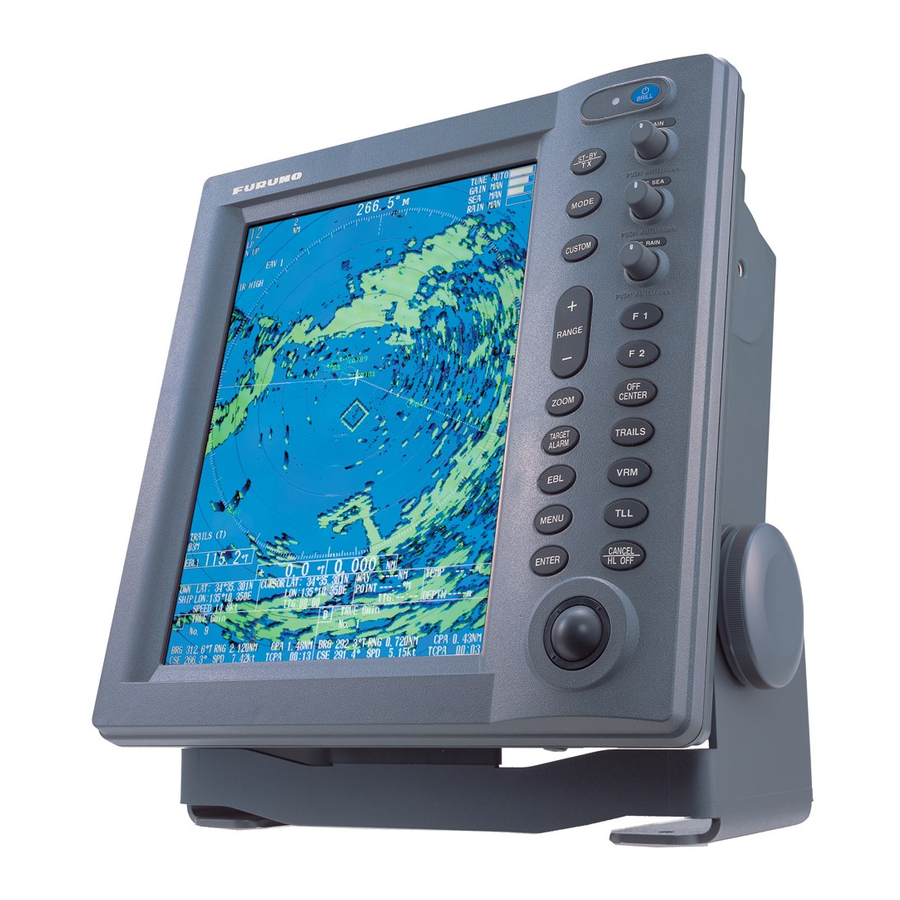
OPERATIONAL OVERVIEW This chapter provides the information necessary for operating this radar. Controls 1.1.1 Display unit This radar is operated with the controls of the display unit (and the remote controller). 17 keys are labeled and they provide the function shown on their labels. The trackball's main function is to move the cursor across the screen. - Page 13 1. OPERATIONAL OVERVIEW Control description Control Description POWER/BRILL Momentary press: Turns power on; adjusts brilliance. Long press: Turns power off. STBY/TX Ttransmits radar pulses and places radar in standby alternately. MODE Chooses presentation mode. CUSTOM Presets radar controls for one-touch setup of radar. RANGE Chooses radar range.
-
Page 14: Remote Controller
1. OPERATIONAL OVERVIEW 1.1.2 Remote controller The remote controller provides armchair control over transmit, standby, rante and display offcen- tering. STBY Offcenters display. Toggles STBY/TX CENTER Chooses range. RANGE Remote controller... -
Page 15: Turning The Radar On/Off, Transmitting
After the tests are completed, the bearing scale and a digital timer appear. The digital timer counts down the time remaining to warm up the magnetron, which transmits the radar pulses. This warm-up takes 90 sec. (FR-8252) or 180 sec. (FR-8062, FR-8122). 12.1" Color LCD... -
Page 16: Display Indications
1. OPERATIONAL OVERVIEW Display Indications Presentation mode Custom settings Heading Range ring interval 359.9° TUNE indicator TUNE AUTO Range GAIN indicator GAIN AUTO Pulse length SP NUP SEA indicator SEA MED HARBOR A/C AUTO RAIN indicator RAIN LOW Echo stretch (ES), EAV1 NR LOW Echo averaging (EAV) -
Page 17: Display Brilliance, Panel Dimmer
1. OPERATIONAL OVERVIEW Display Brilliance, Panel Dimmer The display brilliance and panel dimmer may be adjusted as follows: 1. Press the POWER/BRILL key momentarily to show the brilliance/panel dialog box. Min Max Brill (1 - 15) 9 Panel (1 - 7) 7 [ENTER]: Close Brilliance/panel dimmer dialog box 2. -
Page 18: Tuning
1. OPERATIONAL OVERVIEW 4. Roll the trackball to choose the menu item desired and then press the ENTER key. A window with options for the corresponding menu item appears. For example, the window below shows the options for Trail Color in the Target Trails menu. Green Blue White... -
Page 19: Presentation Modes
1. OPERATIONAL OVERVIEW Presentation Modes This radar has the following presentation modes: Relative Motion (RM) Head-up: Unstabilized Head-up TB: Head-up with compass-stabilized bearing scale (True Bearing) where bearing scale rotates with the compass reading. Course-up: Compass-stabilized relative to ship's orientation at the time of electing course-up. North-up: Compass-stabilized with reference to north True Motion (TM) North-up: Ground or sea stabilized with compass and speed inputs... - Page 20 1. OPERATIONAL OVERVIEW Course-up mode The course-up mode is an azimuth stabilized dis- North Marker Heading Line play in which a line connecting the center with the top of the display indicates own ship's intended course (namely, own ship's previous heading just before this mode has been selected).
-
Page 21: Choosing A Range Scale
1. OPERATIONAL OVERVIEW True motion mode Own ship and other moving objects move in accordance with North Marker Heading Line their true courses and speed. In ground stabilized TM, all fixed targets, such as landmasses, appear as stationary echoes. In the sea stabilized TM without set and drift inputs, the landmass can move on the screen. -
Page 22: Choosing A Pulse Length
1. OPERATIONAL OVERVIEW Choosing a Pulse Length The pulse length in use appears at the top left position on the screen. Appropriate pulse lengths are preset to individual range scales and functions keys. If you are not satisfied with the pulse length setting on the 1.5 nm or 3 nm range, you may change it as below. -
Page 23: Suppressing Sea Clutter
1. OPERATIONAL OVERVIEW 1.10.3 Manual gain adjustment 1. Push the GAIN control to show “GAIN MANL” as the gain adjustment method. 2. Rotate the GAIN control to adjust the gain. Adjust the control so background noise is just visible on the screen. 1.11 Suppressing Sea Clutter Echoes from waves cover the central part of the display with random signals known as sea clutter. -
Page 24: Suppressing Rain Clutter
1. OPERATIONAL OVERVIEW 1.11.3 Manual sea clutter adjustment 1. Push the SEA control to show “SEA MANL” as the SEA adjustment method. 2. Rotate the SEA control to suppress sea clutter. The proper setting of the SEA control should be such that the clutter is broken up into small dots, and small targets become distinguishable. -
Page 25: Automatic Suppression Of Sea And Rain Clutters
1. OPERATIONAL OVERVIEW 1.12.2 Automatic rain clutter adjustment 1. Press the MENU key to open the menu. 2. Choose the Echo menu and then press the ENTER key. 3. Choose Auto Rain and then press the ENTER key. Rough Moderate Calm 4. -
Page 26: Cursor
1. OPERATIONAL OVERVIEW 1.14 Cursor The cursor functions to fthe range and bearing to a target or latititude and longitude position of a target, and the default function is range and bearing. Roll the trackball to position the cursor and then read cursor data at the screen bottom. -
Page 27: Interference Rejector
1. OPERATIONAL OVERVIEW 1.15 Interference Rejector Mutual radar interference may occur in the vicinity of another shipborne radar operating in the same frequency band. It is seen on the screen as a number of bright spikes either in irregular pat- terns or in the form of usually curved spoke-like dotted lines extending from the center to the edge of the picture. -
Page 28: Measuring The Range To A Target
1. OPERATIONAL OVERVIEW 1.16 Measuring the Range to a Target The range to a target may be measured three ways: with the fixed range rings, with the cursor (if set to measure range and bearing), or with the VRM. Use the fixed range rings to obtain a rough estimate of the range to a target. They are the concen- tric solid circles about own ship, or the sweep origin. -
Page 29: Measuring The Bearing To A Target
1. OPERATIONAL OVERVIEW 1.16.3 Choosing VRM unit The unit of measurement used by the VRM can be selected to nautical miles, kilometers, statute miles or kilometers/yard. 1. Press the MENU key to open the menu. 2. Choose the Mark menu and then press the ENTER key. 3. -
Page 30: Measuring The Range And Bearing Between Two Targets
1. OPERATIONAL OVERVIEW 1.17.1 EBL reference The EBL readout is affixed by "R." (relative) if it is relative to own ship's heading, "T." (true) if it is referenced to the north. You may choose relative or true in the head-up modes; in all other modes it is always TRUE. -
Page 31: Target Alarm
1. OPERATIONAL OVERVIEW 1.19 Target Alarm The target alarm serves to alert the navigator to targets (ships, landmasses, etc.) entering a set CAUTION area, with audible and visual alarms. • The alarm should not be relied upon as The guard alarm zone has a fixed width of 0.5 nm the sole means for detecting possible in the radial direction (depth) and is adjustable from collision situations. -
Page 32: Acknowledging The Alarm
1. OPERATIONAL OVERVIEW 1.19.2 Acknowledging the alarm A target in the target alarm zone produces both visual (flashing) and audible (beep) alarms. To silence the audible alarm, press the CANCEL/HL OFF key. The alarm status shows "ALARM1(or 2) ACK." This will deactivate the audible alarm but will not stop the flashing of the offending target. To reactivate the audible alarm, press the CANCEL/HL OFF key The alarm status is then shown as ALARM 1 (or 2) IN(or OUT). -
Page 33: Off Centering The Display
1. OPERATIONAL OVERVIEW 1.19.5 Choosing target strength which triggers target alarm You may choose the target strength level which triggers the alarm as follows: 1. Press the MENU key to open the menu. 2. Choose the Initial sub menu from the System menu and the press the ENTER key. 3. -
Page 34: Zoom
1. OPERATIONAL OVERVIEW Activating automatic off center Press the OFF CENTER key until OFF CENTER appears on the display and the display is not shifted to the cursor location. 1.20.2 Manual off center 1. Place the cursor where you want locate the screen center. 2. -
Page 35: Echo Stretch
1. OPERATIONAL OVERVIEW 1.21.2 Zoom mode You may choose the zoom mode from among Relative, True or Target. 1. Press the MENU key to open the menu. 2. Choose the Mark menu and press the ENTER key. 3. Choose Zoom and then press the ENTER key. Relative True Target... -
Page 36: Echo Averaging
1. OPERATIONAL OVERVIEW 1.23 Echo Averaging The echo average feature effectively suppresses sea clutter. Echoes received from stable targets such as ships appear on the screen at almost the same position every rotation of the antenna. On the other hand, unstable echoes such as sea clutter appear at random positions. To distinguish real target echoes from sea clutter, echoes are averaged over successive picture frames. -
Page 37: Target Trails
1. OPERATIONAL OVERVIEW 1.24 Target Trails The trails of the radar echoes of targets may be displayed in the form of synthetic afterglow. Target trails are chosen either relative or true and may be sea or ground stabilized. True motion trails require a compass signal and own ship speed input. -
Page 38: Trail Gradation
1. OPERATIONAL OVERVIEW 1.24.3 Trail gradation Trails may be shown in single or multiple gradation (monocolor) or in multicolor. 1. Press the MENU key to open the menu. 2. Choose the Target Trails menu and press the ENTER key. 3. Choose Trail Gradation and then press the ENTER key. Single Multiple Rainbow... -
Page 39: Trail Copy
1. OPERATIONAL OVERVIEW 1.24.6 Trail copy Trails are canceled and restarted whenever the range is changed. However, you may continue trails on the same range, without restarting them, when the range is changed to a next larger or smaller range scale. Note however that when the range is changed, only those trails within the previous range are continued;... -
Page 40: Parallel Index Lines
1. OPERATIONAL OVERVIEW 1.24.9 Restarting trails You may clear all target trails to restart the trail process. Target trails are cleared and the trailing process restarts from time count zero at the current target trail plot interval. 1. Press the MENU key to open the menu. 2. -
Page 41: Outputting Target Position, Inscribing Origin Mark
1. OPERATIONAL OVERVIEW 4. Choose the number of parallel index lines to show (2, 3 or 6) or choose Off to turn off the lines. (The actual number of lines visible may be less depending on line interval.) 5. Press the ENTER key. 6. -
Page 42: Temporarily Hiding The Heading Line, Heading Marker
1. OPERATIONAL OVERVIEW 1.26.2 Origin mark mode You may choose origin mark movement from either True or Relative as follows: 1. Press the MENU key to open the menu. 2. Choose Mark and press the ENTER key. 3. Choose Origin Mark Mode and then press the ENTER key. Relative True 4. -
Page 43: Custom Setup
1. OPERATIONAL OVERVIEW 1.28 Custom Setup 1.28.1 About custom setup Every time your navigating environment or task changes, you must adjust the radar, which can be a nuisance in a busy situation. Instead of changing radar settings case by case, it is possible to assign the function keys to provide optimum settings for often encountered situations. -
Page 44: Description Of Custom Setup Items
1. OPERATIONAL OVERVIEW 1.28.2 Description of custom setup items Description of custom setup items Menu item Description of available settings See paragraph; Name Harbor: Optimum setting for short range navigation in a harbor area using a range scale of 1.5 nm or less Long: Optimum setting for long range detection using a range scale of 6 nm or larger Sea: Optimum setting for navigating in heavy seas. -
Page 45: Programming Function Keys (F1 And F2 Keys)
1. OPERATIONAL OVERVIEW 1.29 Programming Function Keys (F1 and F2 keys) Less-often used functions are provided in the menu. To avoid opening the menus to set up the radar for a particular situation, you may program a function key to provide one-touch access to a desired function. -
Page 46: Suppressing Second-Trace Echoes
1. OPERATIONAL OVERVIEW 1.31 Suppressing Second-trace Echoes In certain situations, echoes from very distance targets may appear as false echoes (second-trace echoes) on the screen. This occurs when the return echo is received one transmission cycle later, or after a next radar pulse has been transmitted. Tx repetition Second-trace echo... -
Page 47: Color Schemes
1. OPERATIONAL OVERVIEW 1.33 Color Schemes 1.33.1 Preset color schemes Preset color schemes are provided for optimum viewing in daytime, nighttime and twilight. A user arrangeable color scheme is also provided. Below are the default color settings for each preset color scheme. -
Page 48: Navigation Data
1. OPERATIONAL OVERVIEW 1.34 Navigation Data 1.34.1 Navigation data during standby Navigation data is shown when the radar is in standby. Appropriate sensors required to display data. XTE-track Time until Tx in watchman Heading error (Displayed when watchman is active.) <WATCH>... -
Page 49: Navigation Data At The Bottom Of The Screen
1. OPERATIONAL OVERVIEW Depth and water temperature graphs These graphs display the latest 30 minutes of respective data. The horizontal axis scale is updated and plotted at intervals of 10 seconds. The vertical axis scale is adjusted automatically for every 30 minutes of data. The unit of measurement may be chosen on the Initial sub menu in the System menu. -
Page 50: Dynamic Range
1. OPERATIONAL OVERVIEW 1.35 Dynamic Range In radar systems, system dynamic range is crucial for differentiating between highly reflective tar- gets and those which do not have optimum reflective properties. You may change the dynamic range to better differentiate those targets as below. 1. -
Page 51: Antenna Speed
1. OPERATIONAL OVERVIEW 1.37 Antenna Speed The antenna speed may be changed to meet operating requirement. Choose a high speed when cruising at high speed to ensure timely update of radar targets. Note that the speed cannot be changed on the 24 rpm motor; it is fixed at 24 rpm. 1. -
Page 52: Alarm Message Display
1. OPERATIONAL OVERVIEW 1.39 Alarm Message Display When a violation occurs the radar generates audible and visual alarms to alert you. The alarm message display shows all alarms currently violated. You may show this display as follows: 1. Press the MENU key to open the menu. 2. -
Page 53: Echo Area
1. OPERATIONAL OVERVIEW List of alarm messages Category Alarm name Alarm name AIS system TX stopped or TX error Antenna VSWR trouble TDM2 RX1 board trouble TDM2 RX2 board trouble CH70 RX channel 70 trouble FAIL System failure EPFS External EPFS trouble Position data lost Speed data lost Course data lost... -
Page 54: Customizing (Initial Menu)
1. OPERATIONAL OVERVIEW 1.41 Customizing (Initial Menu) The Initial sub menu in the System menu contains items which allow you to customize your radar to meet your operational needs. 1.41.1 Opening the Initial menu 1. Press the MENU key to open the menu. 2. - Page 55 1. OPERATIONAL OVERVIEW Range Preset: You may choose the radar ranges you wish to use. When you choose Range Preset the option window shown below appears. Choose a range and press the ENTER key to turn that range on or off. At least two ranges must be turned on. The maximum range available depends on radar model.
-
Page 56: Radar Observation
RADAR OBSERVATION General 2.1.1 Minimum and maximum ranges Minimum range The minimum range is defined by the shortest distance at which, using a scale of 1.5 or 0.75 nm, a target having an echoing area of 10 m2 is still shown separate from the point representing the antenna position. -
Page 57: Radar Resolution
This is determined by pulse length only. Practically, a 0.08 microsecond pulse offers the discrimination better than 35 m as do so with all FURUNO radars. Test targets for determining the range and bearing resolution are radar reflectors having an echoing area of 10 m2. -
Page 58: False Echoes
2. RADAR OBSERVATION False Echoes Occasionally echo signals appear on the screen at positions where there is no target or disappear even if there are targets. They are, however, recognized if you understand the reason why they are displayed. Typical false echoes are shown below. 2.2.1 Multiple echoes Multiple echoes occur when a transmitted pulse returns from a solid object like a large ship, bridge,... -
Page 59: Virtual Image
2. RADAR OBSERVATION 2.2.3 Virtual image A relatively large target close to your ship may be represented at two positions on the screen. One of them is the true echo directly reflected by the target and the other is a false echo which is caused by the mirror effect of a large object on or close to your ship as shown in the figure below. -
Page 60: Sart (Search And Rescue Transponder)
2. RADAR OBSERVATION SART (Search and Rescue Transponder) 2.3.1 SART description A Search and Rescue Transponder (SART) may be triggered by any X-Band (3 cm) radar within a range of approximately 8 nm. Each radar pulse received causes it to transmit a response which is swept repetitively across the complete radar frequency band. -
Page 61: Racon
2. RADAR OBSERVATION 2.3.2 General remarks on receiving SART SART range errors When responses from only the 12 low frequency sweeps are visible (when the SART is at a range greater than about 1 nm), the position at which the first dot is displayed may be as much as 0.64 nm beyond the true position of the SART. -
Page 62: Arp Operation
ARP OPERATION The Automatic Radar Plotter ARP-11 (option) manually or automatically acquires and tracks ten targets. Once a target is acquired automatically or manually it is automatically tracked within 0.1 to 32 nm. Usage Precautions CAUTION CAUTION CAUTION CAUTION No one navigational aid should be relied The plotting accuracy and response of upon for the safety of vessel and crew. -
Page 63: Controls For Use With Arp
3. ARP OPERATION Controls for Use with ARP ENTER: Acquires cursor-selected target; Displays data for tracked target (in the data box at the bottom of the screen). CANCEL/HL OFF: Removes data of cursor-selected tracked target from the data box; stops tracking cursor-selected (when its data is not displayed in the data box. -
Page 64: Acquiring And Tracking Targets
3. ARP OPERATION Acquiring and Tracking Targets Ten targets may be acquired and tracked manually and automatically. When you attempt to acquire an 11th target, the message "ARP FULL - ALREADY TRACKING 10 TARGETS!" appears for five seconds. To acquire another target, terminate tracking of an unnecessary target, as shown in the paragraph 3.5. -
Page 65: Terminating Tracking Of Arp Targets
3. ARP OPERATION 3. Choose Auto Acquire and then press the ENTER key. 4. Choose On to enable automatic acquisition. 5. Press the ENTER key. 6. Press the MENU key to close the menu. Terminating Tracking of ARP Targets When ten targets have been acquired, no more acquisition occurs unless targets are cancelled. If you need to acquire additional targets, you must first cancel one or more individual targets, or all targets, using one of the procedures below. -
Page 66: Vector Attributes
3. ARP OPERATION Vector Attributes What is a vector? A vector is a line extending from a tracked target which shows estimated speed and course of the target. The vector tip shows an estimated position of the target after the selected vector time elapses. -
Page 67: History Display (Target Past Position)
3. ARP OPERATION History Display (target past position) This radar can display time-spaced dots (maximum ten dots) marking the past positions of any ARP/AIS target being tracked. You can evaluate a target's actions by the spacing between dots. Below are examples of dot spacing and target movement.. (a) Ship turning (b) Ship running (d) Ship increased... -
Page 68: Arp Target Data
3. ARP OPERATION ARP Target Data You can show target data (range, bearing, course, speed, CPA and TCPA) for two tracked ARP targets, in the data box at the bottom of the screen. To display ARP target data, the ARP display must be active and the menu item Data Box in the Display sub menu must be set for Target or All. -
Page 69: Cpa And Tcpa Alarm
3. ARP OPERATION CPA and TCPA Alarm When the predicted CPA of any ARP/AIS target becomes smaller than a preset CPA alarm range or its predicted TCPA less than a preset TCPA alarm limit, an audio alarm sounds and the collision visual alarm is generated.. -
Page 70: Proximity Alarm
3. ARP OPERATION 3.10 Proximity Alarm The proximity alerts you by audio and visual alarms when an ARP/AIS target is within the range you specify. 1. Press the MENU key to open the menu. 2. Choose Target and then press the ENTER key. 3. -
Page 71: Symbol Color
3. ARP OPERATION 3.12 Symbol Color You may choose the ARP/AIS symbol color from among Green, Red, Blue, White or Black. 1. Press the MENU key to open the menu. 2. Choose ARP and then press the ENTER key. 3. Choose Symbol Color and then press the ENTER key. Green Blue White... -
Page 72: Ais Operation
AIS OPERATION Connected to an AIS Transponder via an AIS Interface, the FR-8xx2 series can show the name, position and other nav data of the nearest 100 AIS transponder-equipped ships. This radar accepts position data fixed by WGS-84 geodetic datum. Set the datum to WGS-84 on the GPS navigator connected to this radar. -
Page 73: Ais Symbols
4. AIS OPERATION AIS Symbols When the AIS is turned on, AIS targets are marked with appropriate AIS symbol as below. Sleeping target Activated target Dangerous Lost target Target selected target for data display AIS symbols Note 1: AIS symbols are momentarily erased after the screen is redrawn when the heading is changed in the Head-up mode. -
Page 74: Displaying Ais Target Data
4. AIS OPERATION Displaying AIS Target Data Place the cursor on the active target that you want to know its data. AIS Target + 110.1°R 2.525 NM Data box A Data box B Data box (A or B) MMSI of vessel Vector reference Vector time Name of... -
Page 75: Display Range
4. AIS OPERATION Display Range You may set the AIS target display range as below. This allows you to view only those AIS targets within the range you specify. The setting range is 0-96 miles but actual range depends on the con- nected AIS Transponder. -
Page 76: Display Sector
4. AIS OPERATION Display Sector You may choose the area where to display AIS targets. The range of the sector may be from 0° to 359°. 1. Press the MENU key to open the menu. 2. Choose AIS and then press the ENTER key. 3. -
Page 77: Vector Attributes
4. AIS OPERATION 4.10 Vector Attributes What is a vector? A vector is a line extending from a tracked target which shows estimated course of the AIS target. The vector tip shows an estimated position of the target after the selected vector time elapses. It can be useful to extend the vector length (time) in order to evaluate the risk of collision with any target. -
Page 78: History Display (Target Past Position)
4. AIS OPERATION 4.11 History Display (target past position) This radar can display time-spaced dots (maximum ten dots) marking the past positions of any ARP/AIS target being tracked. You can evaluate a target's actions by the spacing between dots. Below are examples of dot spacing and target movement. (a) Ship turning (b) Ship running (d) Ship increased... -
Page 79: Cpa And Tcpa Alarm
4. AIS OPERATION 4.12 CPA and TCPA Alarm When the predicted CPA of any ARP/AIS target becomes smaller than a preset CPA alarm range or its predicted TCPA less than a preset TCPA alarm limit, an audio alarm sounds and the symbol of the offending AIS target changes to the dangerous target symbol. -
Page 80: Proximity Alarm
4. AIS OPERATION 4.13 Proximity Alarm The proximity alerts you by audio and visual alarms when an ARP/AIS target is within the range you specify. 1. Press the MENU key to open the menu. 2. Choose Target and then press the ENTER key. 3. -
Page 81: Symbol Color
4. AIS OPERATION 4.15 Symbol Color You may choose the ARP/AIS symbol color from among Green, Red, Blue, White or Black. 1. Press the MENU key to open the menu. 2. Choose ARP and then press the ENTER key. 3. Choose Symbol Color and then press the ENTER key. Green Blue White... -
Page 82: Gps Operation
GPS OPERATION With connection of a FURUNO GPS navigator, you may set up the GPS navigator from this radar. Navigator Type 1. Press the MENU key to show the menu. 2. Choose GPS and then press the ENTER key. Menu... -
Page 83: Datum
5. GPS OPERATION Datum Choose the datum type which matches the paper nautical charts you are using. Choose WGS-84 if the radar is interfaced to an AIS Transponder. 1. Press the MENU key to show the menu. 2. Choose GPS and then press the ENTER key. 3. -
Page 84: Satellite Monitor
5. GPS OPERATION Satellite Monitor The Satellite Monitor provides comprehensive information about GPS and WAAS satellites. For more detailed information, see your GPS navigator’s owner’s manual. 1. Press the MENU key to show the menu. 2. Choose GPS and then press the ENTER key. 3. -
Page 85: Type 16 Message
5. GPS OPERATION Type 16 Message The type 16 message provides weather information. It is transmitted by the Japan Maritime Safety Agency, thus you must be within the transmitting range of a japanese DGPS reference station to receive this type of message. You may display this type of message as follows: 1. -
Page 86: Gps Sensor Installation Position Offset
5. GPS OPERATION GPS Sensor Installation Position Offset The installation position of the GPS sensor antenna and the radar antenna must be the same in order to get accurate position information on the radar. If they are different, measure the distance between the GPS sensor antenna and the radar antenna, in the bow/stern and/or port/starboard direction, and enter those distances in the radar as follows: 1. -
Page 87: Cold Start
5. GPS OPERATION Cold Start A cold start may be necessary in the following conditions: • If the GPS receiver has been powered off for a long period of time. • The vessel has far away from the previous fixing position (e.g., more than 500 km). •... -
Page 88: Maintenance & Troubleshooting
MAINTENANCE & TROUBLESHOOTING This chapter provides the necessary procedures for maintenance and troubleshooting. Follow the recommend procedures to keep your radar in good working order. WARNING Do not open the equipment. Hazardous voltage which can cause electrical shock exists inside the equipment. Only qualified personnel should work inside the equipment. -
Page 89: Preventive Maintenance
6. MAINTENANCE & TROUBLESHOOTING Preventive Maintenance Regular maintenance is important for optimum performance. A maintenance program should be established and should at least include the items shown in the table below. Maintenance Interval Item Check point Remedy When The LCD will, in time, Wipe the LCD carefully to prevent necessary accumulate a coating of... -
Page 90: Replacement Of Fuses
10 A Replacing the Magnetron When the magnetron has expired, distant targets cannot be seen on the display. When you feel that long range performance has decreased, contact a FURUNO agent or dealer about replace- ment. Model and magnetron Model Magnetron type Code No. -
Page 91: Trackball Maintenance
6. MAINTENANCE & TROUBLESHOOTING Trackball Maintenance If the cursor skips or moves abnormally, you may need to clean the Trackball. POWER BRILL GAIN STBY PUSH AUTO/MAN MODE PUSH AUTO/MAN CUSTOM RAIN PUSH AUTO/MAN RANGE ZOOM CENTER TARGET TRAILS ALARM MENU CANCEL ENTER HL OFF... -
Page 92: Simple Troubleshooting
6. MAINTENANCE & TROUBLESHOOTING Simple Troubleshooting This section provides simple troubleshooting procedures which the user can follow to restore normal operation. If you cannot restore normal operation do not attempt to check inside the unit. Any trouble should be referred to a qualified technician. Simple troubleshooting If... -
Page 93: Advanced-Level Troubleshooting
6. MAINTENANCE & TROUBLESHOOTING Advanced-level Troubleshooting This paragraph describes how to cure hardware and software troubles which should be carried out by qualified service personnel. Note: This radar equipment contains complex modules in which fault diagnosis and repair down to component level are not practicable by users. Advanced-level troubleshooting Probable cause or Problem... - Page 94 6. MAINTENANCE & TROUBLESHOOTING Advanced-level troubleshooting Probable cause or Problem Remedy check points Range changed but 1) Defective range key 1) Try to operate the RANGE key. If unsuc- cessful, replacement of the keypad may radar picture does not be necessary. change 2) SPU board 2) Replace SPU board.
-
Page 95: System Test
6. MAINTENANCE & TROUBLESHOOTING System Test The diagnostic test checks the system for proper operation. 1. Press the MENU key to open the menu. 2. Use the trackball to choose Factory from the System menu and then press the ENTER key. Factory Factory Menu... - Page 96 6. MAINTENANCE & TROUBLESHOOTING 3. Use the trackball to choose Test and then press the ENTER key. : OK : OK NMEA1 : OK NMEA2 : OK RS-232C : OK PROGRAM NUMBER : 0317101-XX.XX HEADING : OK BEARING : OK TUNE VOLTAGE : 10.1 V INDICATOR VOLTAGE...
-
Page 97: Lcd Test
6. MAINTENANCE & TROUBLESHOOTING • At the right side of the display there are squares, circles and ovals, and they are for checking the controls of the display unit and remote controller. Press each key one by one. The key’s on location “lights” (color depends on color scheme in use) if the key is functioning normally and extinguishes when the key is released. -
Page 98: Gps Test
6. MAINTENANCE & TROUBLESHOOTING GPS Test The FURUNO GPS receiver interfaced with this radar can be checked for proper operation as fol- lows: 1. Press the MENU key to open the menu. 2. Use the trackball to choose GPS and then press the ENTER key. -
Page 99: Clearing The Memory
6. MAINTENANCE & TROUBLESHOOTING 6.10 Clearing the Memory You may wish to clear the memory to restore all default settings, to start afresh. 1. Press the MENU key to open the menu. 2. Use the trackball to choose Factory from the System menu and then press the ENTER key. 3. -
Page 100: Specifications
-28 dB or less (within ±10° of main-lobe) -35 dB or less (±10° of main-lobe or more) RF TRANSCEIVER Frequency and Modulation 9410 MHz ±30MHz (X band), P0N Peak Output Power FR-8062: 6 kW, FR-8112: 12 kW, FR-8052: 25 kW SP - 1 E354S01A... - Page 101 Echo Trail Time, Nav Data (Position, Speed, Course, etc.), ARP/AIS Target Data POWER SUPPLY Rated Voltage/Current FR-8062 - 12-24 VDC: 3.2 A (24 V, no wind) FR-8122 - 12-24 VDC: 3.8 A (24 V, no wind) FR-8252 - 12-24 VDC: 5.0 A (24 V, no wind) Rectifier (option)
- Page 102 FURUNO FR-8xx2 Series Waterproofing Antenna Unit: IPX6 Display Unit: IPX5 Remote Controller, Power Supply Unit: IPX0 Vibration IEC 60945-4th - 2Hz to 5 Hz and up to 13.2 Hz with a deviation of ±1 mm ±10% (7 m/s2 maximum acceleration at 13.2 Hz);...
- Page 103 FURUNO FR-8xx2 Series This page intentionally left blank. SP - 4 E354S01A...
-
Page 104: Index
INDEX Advanced-level troubleshooting, 6-6 measuring bearing by, 1-19 activating targets, 4-2 reference, 1-19 activating, deactivating, 4-1 EBL key, 1-20 controls for, 4-1 Echo area, 1-45 CPA, TCPA alarm, 4-8 Echo averaging, 1-27 display on/off, 4-2 Echo stretch, 1-26 display range, 4-4 display sector, 4-5 F1, F2 key, 1-36 lost target, 4-9... - Page 105 INDEX TARGET ALARM key, 1-21 Target trails Navigation data color, 1-29 at screen bottom, 1-40 gradation, 1-29 standby, 1-39 level, 1-29 Noise rejector, 1-36 long trails, 1-31 North-up mode, 1-9 mode, 1-28 own ship trail, 1-30 OFF CENTER key, 1-24 restarting, 1-31 Offcentering the display, 1-24 starting, 1-28...