Furuno GP-150 Installation Manual
Furuno gps navigation system user manual
Hide thumbs
Also See for GP-150:
- Installation manual (152 pages) ,
- Operator's manual (103 pages) ,
- Operator's manual (99 pages)
Table of Contents
Advertisement
INSTALLATION MANUAL
GPS NAVIGATOR
GP-150
1. SYSTEM CONFIGURATIONS .......................................................................... 1
2. EQUIPMENT LIST............................................................................................ 2
3. DISPLAY UNIT .................................................................................................. 4
4. ANTENNA UNIT ................................................................................................ 6
5. WIRING ........................................................................................................... 10
6. INITIAL SETTINGS ......................................................................................... 12
7. OPTIONAL DGPS ........................................................................................... 23
PACKING LISTS & INSTALLATION MATERIALS........................................... A-1
OUTLINE DRAWINGS ...................................................................................... D-1
INTERCONNECTION DIAGRAM ......................................................................S-1
www.furuno.co.jp
Advertisement
Table of Contents

Related Manuals for Furuno GP-150


Summary of Contents for Furuno GP-150
- Page 1 INSTALLATION MANUAL GPS NAVIGATOR GP-150 1. SYSTEM CONFIGURATIONS ... 1 2. EQUIPMENT LIST... 2 3. DISPLAY UNIT ... 4 4. ANTENNA UNIT ... 6 5. WIRING ... 10 6. INITIAL SETTINGS ... 12 7. OPTIONAL DGPS ... 23 PACKING LISTS & INSTALLATION MATERIALS... A-1 OUTLINE DRAWINGS ...
-
Page 3: Safety Instructions
SAFETY INSTRUCTIONS WARNING Do not work inside the equipment unless totally familiar with electrical circuits. Hazardous voltage which can cause electrical shock, burn or serious injury exists inside the equipment. Turn off the power at the mains switchboard before beginning the installation. Post a sign near the switch to indicate it should not be turned on while the equip-... - Page 4 This page is intentionally left blank.
-
Page 5: System Configurations
SYSTEM CONFIGURATIONS Antenna Unit GPA-019S* Display Unit 12-24VDC Antenna Unit GPA-018S* Antenna Unit GPA-017S** Radar, Echosounder, Autopilot etc. DGPS Beacon Receiver GR-80** *: w/internal beacon receiver **: w/o internal beacon receiver... -
Page 6: Equipment List
EQUIPMENT LISTS Standards Name Type GPA-017S Antenna Unit GPA-018S GPA-019S GP-150-E-N Display Unit GP-150-E-A Installation CP20-01900 Materials CP20-01950 Accessories FP20-01100 Spare Parts SP20-00500 Options Name Flush Mount Kit S OP20-24 Flush Mount Kit F OP20-25 CP20-01700 CP20-02700 Antenna Cable Set... - Page 7 (Continued from the previous page) OP20-32-1 OP20-32 Beacon Receiver Set OP20-33 OP20-34 Rectifier PR-62 DGPS Beacon Receiver GR-80 Whip Antenna FAW-1.2 Printer PP-505-FP Data Switch Box MD-200 2. EQUIPMENT LISTS 000-041-018 With GPA-018S 000-041-019 With whip antenna and OP20-32-1 000-041-596 With GPS-019S 000-041-598 Without whip antenna...
-
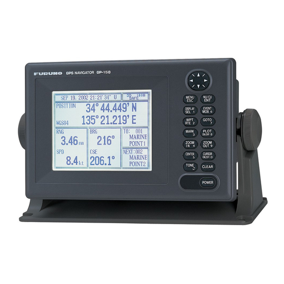
Page 8: Display Unit
DISPLAY UNIT The display unit can be installed with either of four methods as shown below. Refer to the outline drawing at the end of manual. • Locate the unit away from exhaust pipes and vents. • The mounting location should be well ventilated. •... - Page 9 Flush mounting type S An optional flush mount kit type S is required. (Name: Flush Mount Kit S, Type: OP20-24, Code No.: 004-393-000) Name Wing bolt Hex. bolt Wing nut Spring washer Flush mount metal 1. Prepare a cutout in the mounting location whose dimensions are 242 (W) X 152 (H) mm. 2.
-
Page 10: Antenna Unit
ANTENNA UNIT Mounting Install the antenna unit referring to the installation diagram at end of manual. When selecting a mounting location for the antenna unit, keep in mind the following points. • Select a location out of the radar beam. The radar beam will obstruct or prevent reception of the GPS satellite signal. - Page 11 Taping antenna unit GPA-018S After inserting the whip antenna to the antenna base of GPA-018S, tape the antenna base and whip antenna with self-vulcanizing tape and vinyl tape to reinforce the whip antenna. 1. Wrap the antenna junction point with butyl rubber tape No.15 (NITTO SINKO COOP.) or the equivalent.
- Page 12 4. ANTENNA UNIT Extending Antenna Cable Length The standard cable is 15m long. 30m and 50m long extension cable sets are optionally available. Extension cable line-up Fabricate the end of antenna cable and attach the coaxial connector. Details are shown on next page.
- Page 13 How to attach the N-P-8DFB connector Outer Sheath Armor Inner Sheath Shield Cover with heat-shrink tubing and heat. Clamp Gasket (reddish brown) Trim shield here. Insulator Trim aluminum tape foil here. Clamp Nut Solder through the hole. Remove outer sheath and armor by the dimensions shown left.
-
Page 14: Wiring
WIRING The figure below shows the connection of cables on rear of display unit. Antenna Unit GPA-019S GPA-018S GPA-017S 20cm External equipment FUSE 2A CAUTION Ground the display unit to prevent loss of sensitivity and mutual interference. Rear of Display Unit DATA1 DATA2 DATA3... - Page 15 Grounding The display unit contains several CPUs. While they are operating, they radiate noise, which can interfere with other radio equipment. Ground the unit as follows to prevent it. • The grounding wire should be 1.25sq or larger. • The grounding wire should be as short as possible. External Equipment The DATA1, DATA2, and DATA3 ports are used to connect an external equipment such as autopilot, remote display, navigation equipment.
-
Page 16: Initial Settings
The default setting is "manual". Automatic DGPS setup GP-150 can automatically select optimum reference station. If it takes more than five (5) minutes to fix DGPS position at the automatic mode, switch to manual mode. Use the manual mode when an external beacon receiver has no automatic function of station selection. -
Page 17: Manual Dgps Setup
4. Press to select Auto. 5. Press the NU/CU ENT key. 6. Press the MENU ESC key. Manual DGPS setup Enter frequency and baud rate of station. 1. Press MENU ESC, 9 and 7 to display the WAAS/DGPS SETUP menu. 2. - Page 18 You can convert a Loran Plotter to a GPS Plotter with position data from the GP-150. Before selecting data to output, confirm what data the external equipment requires. Output necessary data only.
- Page 19 Data format and data output availability Output data sentence of IEC 61162-1 and NMEA 0183 Ver. 1.5/2.0. AAM: Waypoint arrival alarm APB: Autopilot sentence B magnitude of cross track error, direction to steer, arrival alarm, bearing to waypoint ("Heading to steer to destination waypoint data" not used) BOD: Bearing-origin to destination BWC:...
- Page 20 DPT: Depth HDG: Heading, deviation and variation HDM: Heading, magnetic HDT: Heading, true MTW: Water temperature TLL: Target latitude and longitude VBW: Dual ground/water speed VHW: Water speed and heading. FURUNO proprietary sentence AGFPA: Autopilot information from FURUNO autopilot equipments.
- Page 21 TX rate of operation becomes small. Note 2: When the external equipment cannot display correct data input from the GP-150, the rate of operation should be lowered. For example, set a rate of operation less than 60 % for the Temperature Indicator TI-20.
- Page 22 6. INITIAL SETTINGS DATA 1 output setting 1) Press MENU ESC, 9 and 3. The DATA 1, 3 OUTPUT SETUP menu appears. DATA 1, 3 OUTPUT SETUP Data Fmt. Talker ID Output Data 1. AAM:00 APA:00 2. BWC:00 BWW:00 GGA:00 GLL:01 3.
-
Page 23: Data 2 Output Setting
DATA 2 output setting 1) Press NU/CU MENU, 9 and 4. The DATA 2 OUTPUT SETUP menu appears. Data Fmt. Output Data ENT : Enter 2) Follow the procedure for setting DATA 1 output. DATA 3 output setting The DATA 3 can output NMEA 0183 (V1.5/V2.0) /IEC 61162-1 data or log pulse by selecting inner jumper blocks. - Page 24 6. INITIAL SETTINGS Setting DATA 4 to Data Output 1) Press MENU ESC, 9 and 5. The DATA 4 I/O SETUP menu appears. DATA 4. Level To Next Page ENT : Enter 2) Press to select DATA4. Level. 3) Press to select level of external equipment;...
- Page 25 Setting DATA 4 to “COM.” (general data) Waypoints and Routes data can be received from a personal computer, through the DATA 4 port. 1) Press MENU ESC, 9 and 5. 2) Press to select DATA4. Level. 3) Press to select level of personal computer; RS232C or RS422. 4) Press the NU/CU ENT key.
- Page 26 Setting DATA 4 to DGPS An external DGPS receiver can be connected to the DATA 4 port. Follow the procedure below to setup the GP-150 according to the specifications of the DGPS receiver. 1) Press MENU ESC, 9 and 5.
-
Page 27: Optional Dgps
GP-150 DATA4 TD-A RS-422* TD-B RD-A RD-B When the GP-150 is connected with Beacon Receiver GR-80, do the setting as follows. Signal level First Bit Parity Stop Bit Baud Rate *1: Coincide with the setting of the Beacon Receiver GR-80. - Page 30 工事材料表 INSTALLATION MATERIALS 番 号 名 称 NAME +トラスタッピンネジ 1シュ SELF-TAPPING SCREW 型式/コード番号が2段の場合、下段より上段に代わる過渡期品であり、どちらかが入っています。 なお、品質は変わりませ ん。 TWO TYPES AND CODES MAY BE LISTED FOR AN ITEM. THE LOWER PRODUCT MAY BE SHIPPED IN PLACE OF THE UPPER PRODUCT. QUALITY IS THE SAME. (略図の寸法は、参考値です。 DIMENSIONS IN DRAWING FOR REFERENCE ONLY.) 004-369-790-00 CODE NO.
- Page 31 OUTLINE PART ヒューズ FUSE MFR'S NAME FURUNO ELECTRIC CO.,LTD. (略図の寸法は、参考値です。 DIMENSIONS IN DRAWING FOR REFERENCE ONLY.) 型式/コード番号が2段の場合、下段より上段に代わる過渡期品であり、どちらかが入っています。 なお、品質は変 わりません。 TWO TYPES AND CODES MAY BE LISTED FOR AN ITEM. THE LOWER PRODUCT MAY BE SHIPPED IN PLACE OF THE UPPER PRODUCT. QUALITY IS THE SAME.
- Page 32 Antenna Cable Set CP20-01700 (004-372-110) CP20-01710 (004-372-120) 工事材料表 INSTALLATION MATERIALS 番 号 名 称 NAME 変換ケーブル組品 CONVERT CABLE ASSY. ビニルテープ VINYL TAPE コネクタ(N) CONNECTOR 絶縁テープ SELF-BONDING TAPE 工事材料表 INSTALLATION MATERIALS 番 号 名 称 NAME アンテナケーブル組品 ANTENNA CABLE ASSY. アンテナケーブル組品 CABLE ASSY. CODE NO.
- Page 33 Antenna Cable Set CP20-02700 (004-381-160) CP20-02710 (004-381-170)
- Page 37 Dー4...
- Page 38 Mar,27'07 R.Esumi...
- Page 39 Feb. 19, '03...
- Page 40 Feb. 19, '03...
- Page 44 Nishinomiya, 662-8580, JAPAN Telephone : +81-(0)798-65-2111 : +81-(0)798-65-4200 All rights reserved. Printed in Japan Pub. No. IME-44400-D (HIMA ) GP-150 The paper used in this manual is elemental chlorine free. ・FURUNO Authorized Distributor/Dealer A : FEB D : NOV . 06, 2008...