Furuno GP-150 Operator's Manual
Hide thumbs
Also See for GP-150:
- Installation manual (152 pages) ,
- Operator's manual (103 pages) ,
- Operator's manual (2 pages)
Table of Contents
Advertisement
Advertisement
Table of Contents
Troubleshooting

Related Manuals for Furuno GP-150


Summary of Contents for Furuno GP-150
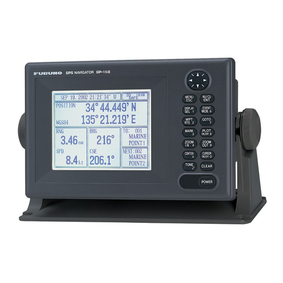
- Page 1 OPERATOR'S MANUAL GPS NAVIGATOR GP-150 MODEL www.furuno.co.jp...
- Page 2 : +81-(0)798-65-4200 A : FEB 2006 All rights reserved. Printed in Japan B3 : MAY 13, 2009 Pub. No. OME-44400-B3 *00015801411* *00015801411* (TATA ) GP-150 *00015801411* *00015801411* * 0 0 0 1 5 8 0 1 4 1 1 *...
-
Page 3: Important Notice
The operator of this equipment must read and follow the descriptions in this manual. Wrong operation or maintenance can cancel the warranty or cause injury. x Do not copy any part of this manual without written permission from FURUNO. x If this manual is lost or worn, contact your dealer about replacement. - Page 4 SAFETY INSTRUCTIONS CAUTION WARNING Use the correct fuse. Do not open the cover of the equipment. Use of the wrong fuse can cause fire or equipment damage. This equipment uses high voltage electricity which can No single navigation aid (including this shock, burn or cause death.
-
Page 5: Table Of Contents
5.4 Finding Range and Bearing Between TABLE OF Two Points........5-7 CONTENTS 6. SETTING UP VARIOUS DISPLAYS 6.1 Selecting Data to Display on the Data Display ........6-1 6.2 Selecting Position Format ....6-2 6.3 Demo Display ........6-4 FOREWORD..........iv 7. ALARMS SYSTEM CONFIGRATION ....... v 7.1 Arrival Alarm, Anchor Watch Alarm..7-1 7.2 Cross Track Error (XTE) Alarm ..7-2 1. -
Page 6: Foreword
The main features of the GP-150 are FOREWORD x Comprehensive navigation data displays x Storage for 999 waypoints and 30 routes A Word to GP-150 Owners x Alarms: Waypoint Arrival, Anchor Watch, Congratulations on your choice of the Cross-track Error, Ship's Speed, Water FURUNO GP-150 GPS Navigator. -
Page 7: System Configuration
SYSTEM CONFIGURATION Antenna Unit GPA-018S* Antenna Unit GPA-019S* Antenna Unit GPA-017S** Radar, Echosounder, Autopilot etc. Display Unit DGPS Beacon Receiver 12-24VDC GR-80** *: w/internal beacon receiver **: w/o internal beacon receiver CATEGORY OF UNITS Unit Category ANTENNA UNIT Exposed to weather DISPLAY UNIT Protected from weather... - Page 8 This page intentionally left blank.
-
Page 9: Operational Overview
1. OPERATIONAL OVERVIEW 1.1 Control Description Cursor pads Shift display and cursor. MENU NU/CU Opens/closes menu; Selects display orientation; quits current operation. registers selections on menus. DISPLAY EVENT Inscribes event mark at Selects display mode. ship’s position; marks man overboard position GOTO Registers waypoints Sets destination. -
Page 10: Turning On And Off The Power
Turning On and Off the When turning on the power the following occurs: Power The GP-150 takes about 90 seconds to find 12 seconds after turning on the power, position when turned on for the very first time. accurate position (in latitude and longitude) Thereafter it takes about 12 seconds to find appears on the display. -
Page 11: Adjusting Display Contrast And Brilliance
1. OPERATION Adjusting Display Selecting the Display Contrast and Brilliance Mode 1) Press the TONE key. The display shown 1) Press the DISPLAY SEL key. The display in Figure 1-3 appears. shown in Figure 1-4 appears. Select Display Plotter 1 Plotter 1 Plotter 2 Tone:... -
Page 12: Plotter 1/2/Highway Display
1. OPERATION Plotter 1 display Plotter 2 display Cursor position data, Bearing from own ship when cursor is on Ship's position appears when cursor is off to destination waypoint RAIM Course GPS receiving Own ship's reliability* condition track Own ship Alarm D3D 100m Distance for... -
Page 13: Navigation Display
1. OPERATION Navigation display 2) With autopilot connection, automatic mode 1) No autopilot connection 100m Cross track SAFE Bearing from own error meter ship to destination 12.3 waypoint Bearing Destination Speed over ground scale Velocity To waypoint no. Destination BRG: 10.3 100m COG:... -
Page 14: Icons
1. OPERATION Data display Refer to Chapter for user-defined window setting. The OOM icon can be displayed by pressing the C SO ON O key. Position in latitude and longitude or LOPs U: UTC Fixing date and time* J: JST Zoom icon S: Ship's time 100m... -
Page 15: Enlarging/Shrinking The Display
Shi ting the Cursor 2. T AC The cursor can be shifted with the cursor pads. Enlarging Shrin ing the 1) Press the C SO ON O key to turn on the cursor. Display 2) Press the cursor pads. ou may enlarge and shrink the display on The cursor moves in the direction of the the Plotter 1, Plotter 2 and Highway displays, cursor pads pressed. -
Page 16: Shifting The Display
2. TRAC Centering Cursor Cursor turned o Position Ship s position (in latitude and longitude or OPs), speed and course appear on the 1) Press the C SO ON O key to turn display. on the cursor. Own ship Own ship position 2) Press the cursor pad to position the mark in latitude and longitude... -
Page 17: Erasing Track
2. TRACK Hold icon Erasing Track (appears while recording of track is stopped) The track stored in the memory and displayed on the screen can be erased. D3D 100m 23.456· N 135q 45.678· E SAFE CAUTION 234q Track cannot be restored once erased. Be absolutely sure you want to erase all track. -
Page 18: Selecting Track Plotting Interval
2. TRACK 3) Press to select Track Rec. Are you sure to erase ? 4) Press to select Time. 5) Enter plotting interval in four digits. To enter 30 seconds, for example, press 0, ENT: Yes MENU: No 0, 3, 0. Figure 2-6 Prompt for erasure 6) Press the NU/CU ENT key. -
Page 19: Apportioning The Memory
2. TRACK 2.10 Apportioning the 3) Press 1 to display the PLOTTER SETUP menu. Memory PLOTTER SETUP The memory holds 2,000 points of track and Trk = 1000 / 2000Pt Memory Apportion marks and may be apportioned as you like. Bearing Ref. -
Page 20: Selecting Bearing Reference
2. TRACK 2.11 Selecting Bearing Entering magnetic variation Reference The location of the magnetic north pole is different from the geographical north pole. Ship's course and bearing to waypoint may This causes a difference between the true be displayed in true or magnetic bearing. and magnetic north direction. -
Page 21: Marks
Erasing marks 3. MARKS CAUTION Entering/Erasing Marks All marks, including event marks and the MOB mark, are erased on the ERASE Marks can be inscribed on the Plotter 1 and MARK menu. Be absolutely sure you want Plotter 2 displays. You may inscribe a mark to erase all marks;... -
Page 22: Selecting Mark Shape
3. MARKS Selecting Mark Shape Connecting Marks (selecting mark connection 13 mark shapes are available. Select mark line) shape as follows: Marks can be connected with lines. Three 1) Press MENU ESC and 2 to display the types of connection lines are available and TRACK/MARK SETUP menu. -
Page 23: Entering Event Marks
3. MARKS Entering Event Marks Selecting Event Mark Shape Event marks can denote any important present position. Event marks can be saved Event marks are available in 10 shapes. as ordinary marks and the unit automatically Select event mark shape as follows. numbers them from 01 to 99. -
Page 24: Entering The Mob Mark
3. MARKS Entering the MOB Mark 2) Press the NU/CU ENT key. f the display in use is ighway avigation or ata The M mark denotes man overboard they are automatically replaced by the position. To mark man overboard position Plotter display. -
Page 25: Navigation Planning
Waypoints are automatically given the The GP-150 can store 999 waypoints, youngest empty waypoint number and numbered from 001-999. Waypoints can be this number appears on the third line. - Page 26 4. NAVIGATION PLANNING 6) Press to select waypoint mark shape. 10) Press the NU/CU ENT key. The following display appears. Control is returned to the last used display mode. When the waypoint number entered at step 5 already exists, the message : Cursor shown in Figure 4-4 appears if the ENT: Enter...
- Page 27 4. NAVIGATION PLANNING Registering waypoints by MOB Registering waypoints by own ship's position/event position position The MOB position or an event position can Note: When there is no position data, you be registered as a waypoint. Event marks cannot register a waypoint at own ship's are numbered from 01 to 99;...
- Page 28 4. NAVIGATION PLANNING Note: Alternatively, you may enter position, WAYPOINT LIST (L/L) leaving the waypoint number blank. 12.345’ N 130q 23.456’ W MARINE POINT AUG 12’ 95 12 : 35U 4) Enter range and bearing you wish to use 12.345’ N 135q 23.456’...
-
Page 29: 4.2 Editing Waypoints
4. A 4.2 Editing Waypoints Deleting Waypoints 1) Press WPT RTE and 5. Deleting waypoints by the cursor 2) Press to select waypoint to 1) Place the cursor on the waypoint to edit. delete. 3) Press 2) Press the CLEAR key. 4) Edit the contents of the waypoint. -
Page 30: Registering Routes
Use: In use Fwd: Traverse waypoints in forward order The GP-150 can store 30 routes and each Rvs: Traverse waypoints in reverse order route may contain up to 30 waypoints. Figure 4-15 Route editing screen Routes can be registered while in the Plotter 1 or Plotter 2 display mode. -
Page 31: Deleting Route Waypoints
4. A Using previously registered waypoints Replacing Route Waypoints Enter waypoints in the order they will be traversed not by waypoint number order. 1) Press PT RTE and 6 to display the ) Press . The reverse video on the route list. -
Page 32: Deleting Routes
4. NAVIGATION PLANNING Deleting Routes 1) Press WPT RTE and 6 to display the route list. 2) Press to select route to delete. 3) Press the CLEAR key. The display shown in Figure 4-17 appears if the route is in use. 1st line Are you sure to erase ? ENT: Yes... -
Page 33: Starting For Destination
A dashed consisting of 30 points. When all 30 points line connects own ship and the are entered, the GP-150 automatically destination, which is marked with a flag, disables further entry. as shown in Figure 5-4. - Page 34 5. STARTING FOR DESTINATION Flag mark Overwriting ? ENT:Yes MENU:No Figure 5-6 8) Press the NU/CU ENT key. Figure 5-4 Single destination set by cursor The waypoints do not have waypoint numbers, however you can attach waypoint numbers by doing the following. Setting multiple destinations Press WPT RTE and 6 to display the 1) Press GOTO and 1.
- Page 35 5. STARTING FOR DESTINATION Setting destination by MOB position or Setting destination through waypoint event position list Note: This operation cannot be performed when there is no MOB position or Note: A waypoint must exist to set it as event position. The buzzer sounds destination.
- Page 36 5. STARTING FOR DESTINATION Setting destination by waypoint no. Route number can be entered here when this line appears in reverse video. 3) Enter waypoint number, in three digits. GOTO (Route List) FORWARD You can clear entry by pressing the Route No.
-
Page 37: 5.2 Canceling Destination
5. STARTING FOR DESTINATION Skipping route waypoints 2) Press to select route waypoint to skip. You may skip route waypoints by displaying 3) Press to shift the cursor to the "DI" (DIsable) next to the route waypoint in right of the waypoint number. the route list. -
Page 38: Erasing Route Waypoints (Flags)
5. STARTING FOR DESTINATION Erasing Route When flags are erased Waypoints (flags) When the origin waypoint is erased the waypoint before it becomes the origin 1) Place the cursor on the flag to erase. waypoint. If there is no waypoint before the 2) Press the CLEAR key. -
Page 39: Finding Range And Bearing Between Two Points
5. STARTING FOR DESTINATION 5.4 Finding Range and Calculation Procedure Bearing Between Two You can find the range and bearing between Points two points by two waypoints or two latitude and longitude positions. Selecting Course Sailing Method 1) Press MENU ESC and 5. The MANUAL The range and bearing to a destination are CALCULATION menu appears. - Page 40 5. STARTING FOR DESTINATION 4) Press to shift the cursor to the Trial Speed line. 5) Press to select Auto or Man. Auto uses ship's average speed to calculate time-to-go. 6) If you selected Man, enter speed. 7) Press the NU/CU ENT key. The range, bearing and time-to-go between two points appear on the display.
-
Page 41: Selecting Data To Display On The Data Display
Speed thru water (STW) . SETTIN Time-to-go to waypoint (TT ) A IO S ETA to route Total route distance (RT.DIST)* DISPLAYS Trip distance (TRIP) Trip elapsed time (TRIP TM) Water temperature (W.TMP) , and elocity to destination ( TD)* Selecting Data to Display ALT: Displayed only in 3D position fixing. -
Page 42: Selecting Position Format
6. SETTING UP VARIOUS DISPLAYS Selecting Position Format For Loran LOPs 6) Press to select LC Chain. Position can be displayed in latitude and 7) Key in GRI code referring to the Loran C longitude, Loran C LOPs, or Decca LOPs, chain list appears in the Appendix. - Page 43 6. SETTING UP VARIOUS DISPLAYS Registering waypoints using LOPs 5) Key in LOP1 and LOP2, to enable calculation. 1) Press WPT RTE and 5. 6) Press to calculate LOPs. "Calculating" to display LOPs. 2) Press appears between parentheses during the calculation.
-
Page 44: 6.3 Demo Display
6. SETTING UP VARIOUS DISPLAYS 6.3 Demo Display Note: When the memory is cleared while in the demonstration mode, the The demo display provides simulated equipment starts up in the normal operation of this unit. Own ship tracks, at the mode. -
Page 45: Alarms
1) Press the MENU ESC key. 7. ALARMS 2) Press 4 to display the ALARM SETTINGS menu. ALARM SETTINGS There are seven alarm conditions which Arrival/Anchor Arr. Anc. Alarm Range 0.100nm generate both audible and visual alarms. When an alarm setting is violated, the buzzer Alarm Range 0.050nm sounds and the name of the offending alarm... -
Page 46: Cross Track Error (Xte) Alarm
7. ALARMS Anchor watch alarm Cross Track Error (XTE) Alarm The anchor watch alarm sounds to warn you that own ship is moving when it should be at The XTE alarm warns you when own ship is rest. off its intended course. Alarm Own ship’s setting... -
Page 47: Ship's Speed Alarm
7. ALARMS Ship’s Speed Alarm Trip Alarm The ship’s speed alarm sounds when ship's The trip alarm sounds when the distance run speed is lower or higher (or within) the alarm is greater than the trip alarm setting. range set. 1) Press MENU ESC and 4. -
Page 48: Water Temperature Alarm
7. ALARMS Water Temperature Depth Alarm Alarm The depth temperature alarm sounds when the depth is higher or lower (or within) the The water temperature alarm sounds when preset depth. This alarm requires video the water temperature is higher or lower (or sounder connection. -
Page 49: Menu Settings
UNSAFE: GPS signal is abnormal, therefore smoothed the raw data, however too high a the positioning accuracy is not reliable. Note setting slows response time to change in that the GP-150 does not exclude abnormal latitude and longitude. This is especially signals automatically. - Page 50 8. MENU SETTINGS Geodetic datum Selecting fix mode Select the geodetic chart system you are 1) Press MENU ESC, 9 and 6 to display the using. WGS-84 (standard GPS chart system) GPS SETUP menu. and NAD 27 can be directly selected. For GPS SETUP other charts, select "OTHER"...
- Page 51 8. MENU SETTINGS Entering GPS speed smoothing 4) Press the NU/CU ENT key. Press the MENU ESC key. 1) Press MENU ESC, 9 and 6. 2) Press to select Spd. Entering geodetic datum 3) Enter smoothing factor in three digits (0000-9999).
-
Page 52: Selecting Units Of Measurement
8. MENU SETTINGS Entering position Unit of depth After the unit is installed you may enter 1) Press MENU ESC, 9 and 2. 2) Press to select Unit of Depth. position to shorten the time it takes to find 3) Press to select unit;... -
Page 53: Mark, Character Size And Brilliance
8. MENU SETTINGS Mark, Character Size Waypoint mark size and Brilliance The size of the waypoint mark can be selected to large or small. The DISPLAY SETUP menu lets you select the size and brilliance of various markers. Large waypoint mark No icon With icon Grid tone... -
Page 54: Settings For Connection Of Navigator
. MENU SETTIN S Enlarging characters Settings or Connection o Na igator The si e of the indications of position or user defined display areas can be enlarged on the Besides its fundamental function of Data display. displaying position, the P-1 0 can also 1) On the Data display, with no enlarged output various data to external equipment. - Page 55 DATA 1 is output from DATA 3. When the external equipment cannot display For log pulse, select 200 or 400 pulse per correct data input from the GP-150, the rate second depending on the device connected. of operation should be lowered.
-
Page 56: Receiving Data From Personal Computer
8. MENU SETTINGS Setting DATA 4 to NMEA Receiving Data from Personal Computer The DATA 4 port connects to a personal computer, DGPS receiver or YEOMAN Loading Waypoints/Routes data equipment. Waypoints and Routes data can be downloaded from a personal computer, 1) Press MENU ESC, 9 and 5. - Page 57 8. MENU SETTINGS 13) Press the NU/CU ENT key. The message 2) To quit loading, press the NU/CU ENT shown in Figure 8-14 appears while data key. The cursor shifts to Stop. is being loaded. 3) To start loading, select Start. 4) Press the NU/CU ENT key.
-
Page 58: Waas/Dgps Settings
. ME U SETT 12) Save data at the computer. Loading completed 13) Press the MENU ESC key. hen data is Valid waypoint saved the cursor shifts to Stop. Invalid waypoint : 0 14) Press the MENU ESC key. Press any key Figure 8-21 WAAS/DGPS Setting ) Press the MENU ESC key twice. - Page 59 4) Press to select Auto, Man or selection. This function is available only List. when equipped with the internal beacon For automatic search, the GP-150 receiver. automatically search DGPS reference station. Entering new DGPS stations For manual search, enter frequency of...
- Page 60 USER Setup, connected to the DATA 4 connector, set up and then press to go to the DGPS the GP-150 according to specification of Station (USER) list. DPGS beacon receiver connected as 5) Press to select the station from follows.
-
Page 61: Displaying Gps Monitor Displays
8. MENU SETTINGS or RS422. you want to view. 4) Press the NU/CU ENT key. 3) Press the MENU ESC to escape. 5) Press to select DGPS. Number, bearing and elevation angle of all satellites in view of the GPS receiver appear. Satellites being 6) Press to select To Next Page. - Page 62 8. MENU SETTINGS This page is intentionally left blank. 8-14...
-
Page 63: Maintenance & Troubleshooting
3) Press to select Yes. The following message appears. Clearing the Memory Setting for cold start Are you sure to clear ? The GP-150 has two memories: GPS ENT:Yes MENU:No memory and plotter memory. Clearing the plotter memory Figure 9-3 The plotter memory holds plotted track and 4) Press the NU/CU ENT key. -
Page 64: Preventive Maintenance
. MA TE A CE TR U LES Preventive Maintenance WARNING Regular maintenance is necessary to Use only a 2A fuse in the power cable. maintain performance. Check the items mentioned below monthly to keep the Use of different fuses may cause fire. e uipment in good working order. - Page 65 . MA TE A CE TR U LES DOP error hen P P value exceeds in the 3 mode or P value exceeds 4 in the 2 mode this error occurs and following indication appears. DOP Error Final GPS Time/Position Aug 25, 2006 02:09’43"...
-
Page 66: Troubleshooting
• Tx interval may be set to “0”. Select proper interval. MENU ESC, 9-3, 9-4, 9-5 See the installation manual for further details. • Check appropriate settings on external equipment. • Check connections: GP-150 external equipment TD-A RD-A TD-B RD-B... -
Page 67: Diagnostic Tests
. MAINTENANCE TROUB ESHOOTIN Diagnostic Tests O appears to the right of PS and BEACON when they are normal N and Me ory and I O circuits test 1 hexadecimal figure appear when an 1) Press MEN ESC and to display the abnormality is found. - Page 68 9. MAINTENANCE & TROUBLESHOOTING Display test Automatic testing 1) Press MENU ESC, 8 and 3 to display the This feature conducts all self tests continuously. test pattern screens. 1) Press MENU ESC, 8 and 4. Self tests are 2) To change the test pattern, press the conducted continuously in the order of NU/CU ENT key.
-
Page 69: Menu Tree
MENU TREE Main 1. DISPLAY SETUP Grid (Dark, Light, Off) Course Bar (Dark, Light, Off) Time Mark (Dark, Light, Off) Waypoint Size (Large, Small) Cursor Size (Large, Small) Set/Drift Ave (Off, 10min, 20min, 30min, 1hour, 2hour, 3hour, 5hour, 6 hour) 2. - Page 70 APPE 9. SYSTEM SETTINGS 1. PLOTTER SETUP Memory Apportion (Trk: 1000/2000 Pt) Bearing Ref. (True, Mag) Mag Variation (Auto, Man) (07°W) (00°E) Calculation (RL, GC) SOG, COG, RNG, BRG, User defined #1 t RNG u W. TMP, W. DPT, XTE, dCOG, #2 t SOG u AVR SOG, AVR COG, TTG, ETA, #3 t BRG u...
- Page 71 APPE 6. GPS SETUP Fix Mode (2D, 2/3D) ANT Height (016 ft, 000 - 999 ft) Disable Satellite (1 - 32) GPS Smoothing Posn (0000, 0000 - 9999 sec) Spd (0005, 0000 - 9999 sec) Speed Average (0060, 0000 - 9999 sec) RAIM Function (Off, On) RAIM Accuracy (100, 1 - 999) Geodetic Datum (WGS84, NAD27, OTHER)
-
Page 72: Digital Interface (Iec 61162-1 Edition 2 (2000-07))
Isolation: Optocoupler Input impedance: 470 ohms Max. voltage: ±15V Threshold: 3 mA (in case of connection of FURUNO device talker) Data transmission Data is transmitted in serial asynchronous form in accordance with the standard referenced in 2.1 of IEC 61162-1. The first bit is a start bit and is followed by data bits. - Page 73 DATA 1 port (input) 20P8192 DATA 1 MJ-A6SRMD +3.3V R130 2.2K RD-H PC-400 R123 R182 RD-C CR15 1SS272 • Load Requirements Isolation: opto coupler Ω Input Impedance: 470 ± Max. Voltage: Threshold: 3mA (In case of FURUNO device talker connection) AP-5...
- Page 74 DATA 2 port (input) 20P8192 DATA2 MJ-A6SRMD +3.3V R131 FL10 2.2K RD-H PC-400 R183 R124 RD-C CR15 FL11 1SS272 • Load Requirements Isolation: opto coupler Ω Input Impedance: 470 ± Max. Voltage: Threshold: 3mA (In case of FURUNO device talker connection) AP-6...
- Page 75 APPENDIX DATA 3 port (output) Output drive capability: Max. 15mA 20P8192 DATA3 MJ-A6SRMD SN75ALS172 FL15 TD-A TD-B FL14 DATA 4 port IN/OUT signal is selected by the menu among the output of IEC 61162-1, NMEA Ver. 1.5/2.0, PC input/output and DGPS signal. Sentence description AAM-Waypoint arrival alarm $--AAM,A,A,x.x,N,c--c*hh<CR><LF>...
- Page 76 APPENDIX APB - Autopilot sentence data $--APB,A,A,x.x,a,N,A,A,x.x,a,c--c,x.x,a,x.x,a,a*hh<CR><LF> | | | | | | | | | | | | | | | | | | | +------- 13 | | | | | | | | +--------- 12 | | | | | | | | +--+----------- 11 | | |...
- Page 77 APPENDIX BOD - Bearing, origin to destination $--BOD,x.x,T,x.x,M,c--c,c--c*hh<CR><LF> | +--------- 5 +------------ 4 +----------------- 3 | +--+--------------------- 2 +--+--------------------------- 1 1. Bearing, degrees true 2. Bearing, degrees magnetic 3. Destination waypoint ID 4. Origin waypoint ID 5. Checksum BWC - Bearing and distance to waypoint $--BWC, hhmmss.ss, llll.ll, a yyyyy.yy, a, x.x, T, x.x, M, x.x, N, c--c, a*hh<CR><LF>...
- Page 78 APPENDIX BWR - Bearing, waypoint to range $--BWR,hhmmss.ss,llll.lll,a,yyyyy.yyy,a,x.x,T,x.x,M,x.x,N,c--c,a*hh<CR><LF> | +---- 9 | +------ 8 | +--------- 7 | +--+------------- 6 | +--+------------------- 5 | +--+------------------------- 4 +-----+------------------------------- 3 +-----+------------------------------------------- 2 +---------------------------------------------------------- 1 1. UTC of observation 2. Waypoint latitude, N/S 3.
- Page 79 APPENDIX DBT - Depth below transducer $--DBT, x. x, f, x. x, M, x. x, F*hh<CR><LF> 1. Water depth, feet 2. Water depth, m 3. Water depth, fathoms 4. Checksum DPT - Depth $--DPT,x.x,x.x,x.x*hh<CR><LF> | +----- 4 +--------- 3 +------------ 2 +---------------- 1 1.
- Page 80 APPENDIX DTM - Datum reference $--DTM,ccc,a,x.x,a,x.x,a,x.x,ccc*hh<CR><LF> | | | | | | | +--- 7 | | | +------ 6 | | | | +---------- 5 | | | | +--+------------- 4 | | +---+------------------- 3 | +------------------------- 2 +---------------------------- 1 1.
- Page 81 APPENDIX GGA -Global positioning system fix data $--GGA,hhmmss.ss,llll.lll,a,yyyyy.yyy,a,x,xx,x.x,x.x,M,x.x,M,x.x,xxxx*hh<CR><LF> | | | | | | +-- 11 | | | +---- 10 | | | | +--------- 9 | | | | +---+------------ 8 | | | +---+------------------ 7 | | | +------------------------- 6 | | +---------------------------- 5 | +------------------------------- 4...
- Page 82 APPENDIX GNS - GNSS fixed data $--GNS,hhmmss.ss,llll.lll,a,yyyyy.yyy,a,c--c,xx,x.x,x.x,x.x,x.x,x.x*hh<CR><LF> +--- 11 +------ 10 +---------- 9 +-------------- 8 +------------------ 7 | +---------------------- 6 +------------------------- 5 | +------------------------------ 4 +-------+--------------------------------- 3 +---+--------------------------------------------- 2 +------------------------------------------------------------- 1 1. UTC of position 2. Latitude, N/S 3. Longitude, E/W 4.
- Page 83 APPENDIX RMB - Recommended minimum navigation information $--RMB,A,x.x,a,c--c,c--c,llll.lll,a,yyyyy.yyy,a,x.x,x.x,x.x,A,a*hh<CR><LF> | | | | | +--- 13 | +----- 12 | +------- 11 | +---------- 10 +-------------- 9 | +------------------ 8 +-----+--------------------- 7 +----+--------------------------------- 6 +--------------------------------------------- 5 | | +-------------------------------------------------- 4 | +------------------------------------------------------ 3 | +--------------------------------------------------------- 2 +------------------------------------------------------------ 1 1.
- Page 84 APPENDIX RMC- Recommended minimum specific GPS/TRANSIT data $--RMC,hhmmss.ss,A,llll.lll,a,yyyyy.yyy,a,x.x,x.x,xxxxxx,x.x,a,a*hh<CR><LF> | | | | | | | +--- 10 | | +----- 9 +--+------- 8 +--------------- 7 | +--------------------- 6 | +------------------------- 5 +---+---------------------------- 4 +---+---------------------------------------- 3 +--------------------------------------------------- 2 +---------------------------------------------------------- 1 1. UTC of position fix 2.
- Page 85 APPENDIX TLL - Target latitude and longitude $--TLL,xx,llll.lll,a,yyyyy.yyy,a,c--c,hhmmss.ss,a,a*hh<CR><LF> | | | | | +--------- 8 | +----------- 7 +------------- 6 +-------------------- 5 | +-------------------------- 4 +-----+------------------------------ 3 | +----+------------------------------------------ 2 +----------------------------------------------------- 1 1. Target number 00 - 99 2. Latitude, N/S 3.
- Page 86 APPENDIX VDR – Set and drift $--VDR,x.x,T,x.x,M,x.x,N*hh<CR><LF> | | | | | +--------- 4 | +--+----------- 3 | | +--+----------------- 2 +--+----------------------- 1 1. Direction, degrees true 2. Direction, degrees magnetic 3. Current speed, knots 4. Checksum VHW – Water speed and heading $--VHW,x.x,T,x.x,M,x.x,N,x.x,K*hh<CR><LF>...
- Page 87 APPENDIX WCV - Waypoint closure velocity $--WCV,x.x,N,c--c,a*hh<CR><LF> | | | | | +------- 4 | +--------- 3 | +--+----------- 2 +--+---------------- 1 1. Velocity component, knots 2. Waypoint identifier 3. Mode indicator(see note) 4. Checksum NOTE Positioning system Mode indicator: A = Autonomous D = Differential S = Simulator...
- Page 88 APPENDIX XTE - Cross-track error, measured $--XTE,A,A,x.x,a,N,a*hh<CR><LF> | | | | | | | | | +--------- 7 | | | +----------- 6 | | +------------- 5 NOTE Positioning system Mode indicator: | +--------------- 4 A = Autonomous mode | | +------------------ 3 D = differential mode | +--------------------- 2 S = Simulator mode...
-
Page 89: Time Differences
TIME DIFFERENCES AP-21... -
Page 90: Geodetic Chart List
GEODETIC CHART LIST 001 : WGS84 088 : NORTH AMERICAN 1927 : Western United States 002 : WGS72 089 : : Eastern United States 003 : TOKYO : Mean Vallue (Japan, Korea, and Okinawa) 090 : : Alaska 004 : NORTH AMERICAN 1927 : Mean Vallue (CONUS) 091 : : Bahamas (Excluding San Saivador Island) -
Page 91: Loran C Chains
LORAN C CHAINS c i f – – – – – – – – – – – – – – – – – – – – – – – – – – – c i f – – – – c i f –... -
Page 92: Decca Chains
DECCA CHAINS c i t " " s i t " " " " a l l " s i t " " " " " " c i t " " " a i l " " s i l "... -
Page 93: Parts List
This equipment contains complex modules in which fault diagnosis and repair down to component level are not practical (IMO A.694(17)/8.3.1). Only some discrete components are used. FURUNO Electric Co., Ltd. believes identifying these components is of no value for shipboard maintenance; therefore, they are not listed in the manual. Major modules can be located on the parts location photos on the next page. -
Page 94: Parts Location
Parts Location Display unit GR-7000A (Option) (08S0334) GN-8096 (20S0395) NP Board (20P8192) PNL Board (20P8148) EW50379FDW Display unit, cover opened, GR-7000A installed A-26 A-34... -
Page 95: Specifications
GP-150/Dual SPECIFICATIONS OF GPS NAVIGATOR GP-150/Dual GPS RECEIVER Receiving Frequency 1575.42 MHz Tracking Code C/A code Number of Channel GPS: 12 channels parallel, 12 satellites Position Fixing Method All-in-view, 8-state Kalman filter Accuracy GPS: 10 m approx. (2drms) DGPS: 5 m approx. (2drms) WAAS: 3 m approx. - Page 96 GNS, RMB, RMC, Rnn, RTE, VTG, WCV, WNC, WNR, WPL, XTE, ZDA (or LOGOUT depending on jumper setting for Port 3), Waypoint data to conventional PC (DATA 4 only) * GP-150-Dual: DATA 2 port is used for the system connection. **: GP-150 only POWER SUPPLY Display Unit 12-24VDC: 0.8-0.4A (w/ internal beacon receiver)
- Page 97 INDE Editing Waypoints 4-5 Anchor watch alarm 7-2 Entering marks 3-1 Apportioning the Memory 2-5 entry of comment 4-2 Arrival Alarm 7-1 Entering position 8-3 Automatic testing 9-6 Enlarging characters 8-5 Erasing Track 2-3 Erasing marks 3-1 brilliance 1-3 Erasing Route Waypoints 5-6 Error Messages 9-2 Event Marks 3-3 Canceling Destination 5-5...
-
Page 98: Index
INDEX Magnetic variation 2-6 User-defined display 6-1 Mark Shape 3-2 Unit distance 8-3 mark connection line 3-2 Unit of depth 8-3 Memory and I/O circuits test 9-5 Unit of water temperature 8-4 MOB Mark 3-4 Unit of altitude 8-4 Plotter 1 display 1-4 Water Temperature Alarm 7-4 Plotter 2 display 1-4 Waypoint mark size 8-5... -
Page 99: Declaration Of Conformity
• Test Reports No. FLI 12-03-014 of 12 June 2003, FLI 12-02-040 of 29 August 2003, FLI 12-03-065 of 19 December 2003 and FLI 12-05-047 of 26 October 2005 prepared by Furuno Labotech International Co., Ltd., Nishinomiya, Japan This declaration is issued according to the provisions of European Council Directive 96/98/EC on marine equipment modified by the Commission Directive 2002/75/EC.