Table of Contents
Advertisement
Ferris Industries
5375 North Main Street
Munnsville, NY 13409
800-933-6175
OPERATOR'S
MANUAL
Zero-Turn Riding Mower
Tractor:
Mower Deck:
Model
Model
IS5000Z/C31D
5000/72
IS5000Z/C31DCE
5000/72R
IS5000ZC31D61CE
5000/72RCE
5000/61R
5000/61RCE
IS5000Z Series
Tractor Serial No. 1226 & above
Mower Serial No. 1210 & above
TP 100-7166-00-5Z-F
23458
Revision 00
Rev. Date: 11/2004
Advertisement
Table of Contents
Troubleshooting

Related Manuals for Ferris 5000/61RCE


Summary of Contents for Ferris 5000/61RCE
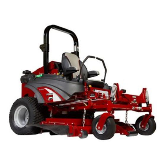
- Page 1 Ferris Industries 5375 North Main Street Munnsville, NY 13409 800-933-6175 OPERATOR’S MANUAL IS5000Z Series Zero-Turn Riding Mower Tractor: Mower Deck: Model Model IS5000Z/C31D 5000/72 IS5000Z/C31DCE 5000/72R IS5000ZC31D61CE 5000/72RCE 5000/61R 5000/61RCE Tractor Serial No. 1226 & above Mower Serial No. 1210 & above...
-
Page 3: Table Of Contents
Safety Rules & Information ...2 Identification Numbers ...5 Safety Decals & Icons...6 Safety Interlock System...7 Features & Controls ...8 Control Functions...8 Operation ...10 General ...10 Checks Before Starting ...10 Priming the Fuel System...11 Starting the Engine ...12 Stopping the Tractor and Engine...12 Driving the Tractor ...12 Mowing...13 Pushing the Rider by Hand...13... -
Page 4: Safety Rules & Information
Read these safety rules and follow them closely. Failure to obey these rules could result in loss of control of unit, severe personal injury or death to you, or bystanders, or damage to property or equipment. This mowing deck is capable of amputating hands and feet and throwing objects. The triangle in text signifies important cautions or warnings which must be followed. - Page 5 23. Use care when approaching blind corners, shrubs, trees or other objects that may obscure vision. 24. To reduce fire hazard, keep unit free of grass, leaves & excess oil. Do not stop or park over dry leaves, grass or combustible materials. 25.
- Page 6 Safety Rules & Information SERVICE AND MAINTENANCE To avoid personal injury or property damage, use extreme care in handling gasoline. Gasoline is extremely flammable and the vapors are explosive. Safe Handling of Gasoline 1. Extinguish all cigarettes, cigars, pipes, and other sources of ignition.
-
Page 7: Identification Numbers
FERRIS FERRIS INDUSTRIES, INC. UNNSVILLE, NY 13409 ADE IN THE USA SERIAL NO. ODEL NO. Model No.: XXXXXXXXXX Engine RPM: XXXX 200X LpA: XX dB(A) Vibration @ Wheels: Vibration @ Seat: Ferris Industries, Inc. Munnsville, NY USA 13409 When contacting your authorized dealer for replace- ment parts, service, or information you MUST have these numbers. -
Page 8: Safety Decals & Icons
SAFETY DECALS This unit has been designed and manufactured to pro- vide you with the safety and reliability you would expect from an industry leader in outdoor power equipment manufacturing. Although reading this manual and the safety instructions it contains will provide you with the necessary basic knowledge to operate this equipment safely and effec- tively, we have placed several safety labels on the unit to remind you of this important information while you are... -
Page 9: Safety Interlock System
SAFETY ICONS Warning: Read Operator’s Manual. Read and understand the Operator’s Manual before using this machine. Danger: Thrown Objects. This machine is capable of throwing objects and debris. Keep bystanders away. Warning: Remove Key Before Servicing. Remove the key and consult techni- cal literature before performing repairs or maintenance. -
Page 10: Features & Controls
Features & Controls Figure 1. CONTROL FUNCTIONS The information below briefly describes the function of the individual controls. Starting, stopping, driving, and mow- ing require the combined use of several controls applied in specific sequences. To learn what combination and sequence of controls to use for various tasks see the OPERATION section. - Page 11 Glow Plug Indicator Indicates that the glow plugs are heating. Holding the ignition key in the “HEAT” position until indicator starts to glow, then turn the key to start. PTO (Power Take Off) Switch The PTO switch engages and disengages the mower. Pull UP on the switch to engage the mower, and push DOWN to disengage the mower.
-
Page 12: Operation
Operation GENERAL OPERATING SAFETY Before first time operation: • Be sure to read all information in the Safety and Operation sections before attempting to operate this tractor and mower. • Become familiar with all of the controls and how to stop the unit. -
Page 13: Priming The Fuel System
PRIMING THE FUEL SYSTEM Priming the fuel system fills the fuel filters and removes any air bubbles from the fuel system. This must be per- formed before the first use, after any fuel filter mainte- nance or if the fuel system is run dry. To prime the fuel system: On the water separator: 1. -
Page 14: Starting The Engine
Operation WARNING If you do not understand how a specific control functions, or have not yet thoroughly read the FEATURES & CONTROLS section, do so now. Do NOT attempt to operate the tractor without first becoming familiar with the location and function of ALL controls. -
Page 15: Mowing
MOWING 1. Engage the parking brake. Make sure the PTO switch is disengaged, the motion control handles are locked in the NEUTRAL position and the operator is on the seat. 2. Start the engine (see STARTING THE ENGINE). 3. Set the mower cutting height. 4. -
Page 16: Zero Turn Driving Practice
ZERO TURN DRIVING PRACTICE The lever controls of the Zero Turn rider are responsive, and learning to gain a smooth and efficient control of the rider’s forward, reverse, and turning movements will take some practice. Spending some time going through the maneuvers shown and becoming familiar with how the unit acceler- ates, travels, and steers —... -
Page 17: Advanced Driving
Practice Turning Around a Corner While traveling forward allow one handle to gradually return back toward neutral. Repeat several times. NOTE: To prevent pivoting directly on the tire tread, it is best to keep both wheels going at least slightly forward. Executing Turns Figure 8. -
Page 18: Storage
Operation STORAGE Temporary Storage (30 Days Or Less) Remember, the fuel tank will still contain some fuel, so never store the unit indoors or in any other area where fuel vapor could travel to any ignition source. Fuel vapor is also toxic if inhaled, so never store the unit in any structure used for human or animal habitation. -
Page 19: Regular Maintenance
Regular Maintenance MAINTENANCE SCHEDULE & PROCEDURES... -
Page 20: Checking/Adding Fuel
Regular Maintenance CHECKING / ADDING FUEL To add fuel: 1. Remove the fuel cap. 2. Fill the tank to the bottom of the fill tube. This will leave room in the tank for fuel expansion. Refer to your engine manual for specific fuel recommenda- tions. -
Page 21: Oil & Filter Change
OIL & FILTER CHANGE Refer to Figure 14 for oil filter, dipstick and filler neck locations. To drain the oil: 1. Place a drain pan below the engine oil pan. 2. Remove the oil drain plug and allow the engine oil to completely drain. -
Page 22: Check Engine Coolant Level
Regular Maintenance CHECK ENGINE COOLANT LEVEL The engine coolant level and quality should be checked before each use, when the engine is cool and off. 1. Remove the radiator pressure cap (A, Figure 17) to check the fluid level. 2. Coolant level should be 1/2” (13mm) below the bot- tom of the filler tube. -
Page 23: Check Warning Lights And Alarm
CHECK INDICATOR LIGHTS AND ALARM 1. Turn the ignition key to the ON position, but DO NOT start the engine. 2. View the indicator light gauge. The red lights con- taining each symbol for water temperature and oil pressure should be illuminated and the alarm should be audible. -
Page 24: Lubrication
Regular Maintenance LUBRICATION Lubricate the unit at the locations shown in Figure 19 through 24. Grease: Use grease fittings when present. Disassemble parts to apply grease to moving parts when grease fittings are not installed. Not all greases are compatible. Ferris Red Grease (P/N 22285) is recommended, automotive-type high- temperature, lithium grease may be used when this is not available. -
Page 25: Battery Maintenance
BATTERY MAINTENANCE (Note: The tractor equipped with a maintenance-free BCI58 battery) Checking the Battery Fluid (Standard battery only. NOT maintenance-free battery.) 1. Raise the seat plate to access battery. 2. Remove the battery filler cap (A, Figure 25). Fluid must be even with the split ring full mark. If not, add distilled water. -
Page 26: Servicing The Mower Blades
Regular Maintenance SERVICING THE MOWER BLADES 1. Blades should be sharp and free of nicks and dents. If not, sharpen blades as described in following steps. 2. To remove blade for sharpening, use a 1” wrench on the flats of the spindle shaft while removing the blade mounting bolt with a 15/16”... -
Page 27: Troubleshooting, Adjustments & Service
TROUBLESHOOTING While normal care and regular maintenance will extend the life of your equipment, prolonged or constant use may eventually require that service be performed to allow it to continue operating properly. The troubleshooting guide below lists the most common problems, their causes and remedies. -
Page 28: Troubleshooting The Mower
Troubleshooting, Adjustment & Service Rider Troubleshooting Continued. PROBLEM Engine runs, but rider will not drive. Hydraulic pump drive belt slips. Brake will not hold. Rider steers or handles poorly. TROUBLESHOOTING THE MOWER PROBLEM Mower will not raise. Mower cut is uneven. Mower cut is rough looking. -
Page 29: Seat Adjustment
SEAT ADJUSTMENT See Figure 29. The seat can be adjusted fore and aft. Move the lever forward, position the seat as desired, and release the lever to lock the seat into position. GROUND SPEED LEVER ADJUSTMENT The control levers can be adjusted in three ways. The alignment of the control levers, the placement of the levers (how close the ends are to one another) and the height of the levers can be adjusted. -
Page 30: Neutral Adjustment
Troubleshooting, Adjustment & Service NEUTRAL ADJUSTMENT If the tractor “creeps” while the ground speed control levers are locked in NEUTRAL, then it may be neces- sary to adjust the control linkage. NOTE: Perform this adjustment on a hard, level surface such as a concrete floor. -
Page 31: Parking Brake Adjustment
PARKING BRAKE ADJUSTMENT 1. Disengage the PTO, stop the engine, block the front wheels, remove the ignition key, and engage the parking brake. 2. Locate the upper brake spring (A, Figure 34). 3. With the parking brake engaged, measure the com- pressed spring length. -
Page 32: Front Suspension Adjustment
FRONT SUSPENSION ADJUSTMENT The shock assembly can be adjusted to vary the amount of pre-load applied to the springs. This allows the oper- ator to customize the ride according to operator’s weight and/or operating conditions. Less Pre-Load: • Light operator weight •... -
Page 33: Mowing Height Adjustment
MOWING HEIGHT ADJUSTMENT See Deck Lift Rod Timing Adjustment and Deck Leveling Adjustment sections to ensure that the actual cutting height is consistent with the cutting height adjustment pin placement. The cutting height adjustment pin (A, Figure 38) controls the mower cutting height. The cutting height is adjustable between 1-1/2”... -
Page 34: Deck Lift Rod Timing Adjustment
Troubleshooting, Adjustment & Service DECK LIFT ROD TIMING ADJUSTMENT 1. Park machine on a flat, level surface. Disengage the PTO, stop the engine and engage the parking brake. Rear tires must be inflated to 18 psi (124 kPa); front tires to 25 psi (172 kPa). 2. -
Page 35: Deck Leveling Adjustment
DECK LEVELING ADJUSTMENT NOTE: Before adjusting the deck level, the deck lift rod timing must be checked and/or adjusted. 1. Park machine on a flat, level surface. Disengage the PTO, stop the engine and engage the parking brake. Rear tires must be inflated to 18 psi (124 kPa); front tires to 25 psi (172 kPa). -
Page 36: Belt Removal & Replacement
Troubleshooting, Adjustment & Service BELT REMOVAL & REPLACEMENT To avoid damaging belts, DO NOT PRY BELTS OVER PULLEYS. Mower Drive Belt Removal & Replacement - 72” Mower Decks 1. Park the tractor on a smooth, level surface such as a concrete floor. - Page 37 BELT REMOVAL & REPLACEMENT To avoid damaging belts, DO NOT PRY BELTS OVER PULLEYS. Mower Drive Belt Removal & Replacement - 61” Mower Deck 1. Park the tractor on a smooth, level surface such as a concrete floor. Disengage the PTO, engage the parking brake, turn off the engine, and remove the ignition key.
-
Page 38: Clutch Drive Belt
Troubleshooting, Adjustment & Service Clutch Belt Removal 1. Park the tractor on a smooth, level surface such as a concrete floor. Disengage the PTO, engage the parking brake, turn off the engine, and remove the ignition key. 2. Remove the rear skid plate by removing the bolts that fasten the skid plate to the bumper and slide the plate forward until it drops from the mounts. -
Page 39: Pump Drive Belt
Pump Drive Belt Removal 1. Park the tractor on a smooth, level surface such as a concrete floor. Disengage the PTO, engage the parking brake, turn off the engine, and remove the ignition key. 2. Remove the clutch belts (see CLUTCH BELT REMOVAL for instructions). -
Page 40: Gearbox Maintenance
Troubleshooting, Adjustment & Service GEARBOX MAINTENANCE Check Gearbox Oil Level 1. Remove fill plug (A, Figure 54) on gearbox. 2. Once plug is removed, oil should seep out of fill plug hole. If no oil drains out, fill with SAE 80-90 weight gear oil until oil starts to seep from hole, then replace fill plug. -
Page 41: Battery Service
BATTERY SERVICE WARNING Keep open flames and sparks away from the battery; the gasses coming from it are highly explosive. Ventilate the battery well during charging. Checking Battery Voltage A voltmeter can be used to determine condition of bat- tery. When engine is off, the voltmeter shows battery voltage, which should be 12 volts. - Page 42 Troubleshooting, Adjustment & Service THIS HOOK-UP FOR NEGATIVE GROUND VEHICLES Starter Switch Starting Vehicle Battery To Ground MAKE CERTAIN VEHICLES DO NOT TOUCH Figure 55. Jump Starting WARNING Any procedure other than the preceding could result in: (1) personal injury caused by electrolyte squirting out the battery vents, (2) personal injury or property damage due to battery explosion,...
-
Page 43: Common Replacement Parts
COMMON REPLACEMENT PARTS Listed below are parts numbers for the more common replacement parts. Use only genuine Ferris replace- ment parts to assure optimum performance and safety. 61” Deck Belt (Gearbox to Spindle) ...23123 61” Deck Blades (Set of 3) ...20842S 61”... -
Page 44: Specifications
Specifications NOTE: Specifications are correct at time of printing and are subject to change without notice. * Actual sustained equipment horsepower will likely be lower due to operating limitations and environmental factors. ENGINE: 31.5 HP* Caterpillar Make Caterpillar Model 3013 Horsepower 31.5 @ 3600 rpm Displacement... -
Page 45: General Information
GENERAL INFORMATION Proper mowing is an important part of maintaining your lawn in the best possible condition. A healthy and well maintained lawn is better able to resist drought, weeds, and other stresses. But too much maintenance is as detrimental to your lawn as neglect. Proper care for your lawn involves more than just “cutting the grass.”... -
Page 46: Lawn Care & Mowing Information
Lawn Care & Mowing Information HOW HIGH TO MOW THE GRASS Often cutting height is a matter of personal prefer- ence. Typically, you should mow the grass when it is is between three and five inches high. The proper cutting height range for a specific lawn will depend upon several factors, including the type of grass,... -
Page 47: When And How Often To Mow
WHAT MOWING PATTERNS TO USE Always start mowing on a smooth, level area. The size and type of area to be mowed will determine the best mowing pattern to use. Obstructions such as trees, fences and buildings, and conditions such as slopes and grades must also be considered. -
Page 48: Mowing Methods
Lawn Care & Mowing Information MOWING METHODS Proper Broadcast Mowing Broadcasting, or side-discharging, disperses fine clip- pings evenly over the entire lawn. Many golf courses use this method. Your mower has a deep dish deck to allow freer circulation of clippings so they are broadcast evenly over the lawn. - Page 49 TIPS On Dealing With Clippings Clippings are beneficial to your lawn. A common mis- conception about clippings is that they automatically lead to thatch—this is untrue. Short clippings produced by broadcasting and clippings produced by mulching methods actually contribute to a healthy lawn because they: COMPOSTING The best way to recycle excess clippings and leave your...
- Page 50 Lawn Care & Mowing Information Stepped Cutting Stepped cutting is sharp ridges or uneven levels left in the lawn surface. Stepped cutting is usually caused by mower deck damage or misadjustment, or damage to mower blades. CAUSE Deck is not leveled correctly Tires are not properly inflated Blades are damaged Deck shell is damaged...
- Page 51 Stingers Stingers are sparse patches of uncut grass left behind the mower. Stingers are usually caused by operator error or poor blade maintenance. CAUSE Blades are not sharp or are nicked Blades are worn down too far Engine speed is too slow Ground speed is too fast Deck is plugged with grass Lawn Care &...
-
Page 52: Technical Manuals
Common International Symbols Choke Fast (Throttle) Slow (Throttle) Throttle Fuel Technical Manuals Additional Technical Literature Available Operators Manuals Additional copies of this manual are available, (and as part of our product support commitment, we maintain a stock of printed operators manuals going back many years!) Parts Manuals Fully illustrated parts manuals are also available —... - Page 53 Notes LC-9...
- Page 55 Ferris Industries, Inc. (Ferris) warrants, in accordance with the provisions below, to the original purchaser only, for the periods described below that the commercial mower shall be free from substantial defects in material or workmanship under normal use and service. If you wish to file a claim under this limited warranty, you must provide prompt notice of your claim to an authorized Ferris dealer during the warranty period.
- Page 56 OPERATOR’S MANUAL IS5000Z Series Zero-Turn Riding Mower Ferris Industries 5375 North Main Street Munnsville, NY 13409 800-933-6175 www.ferrisindustries.com © Copyright 2004 Ferris Industries All Rights Reserved. Printed in USA.