Ferris IS500Z Series Operator's Manual
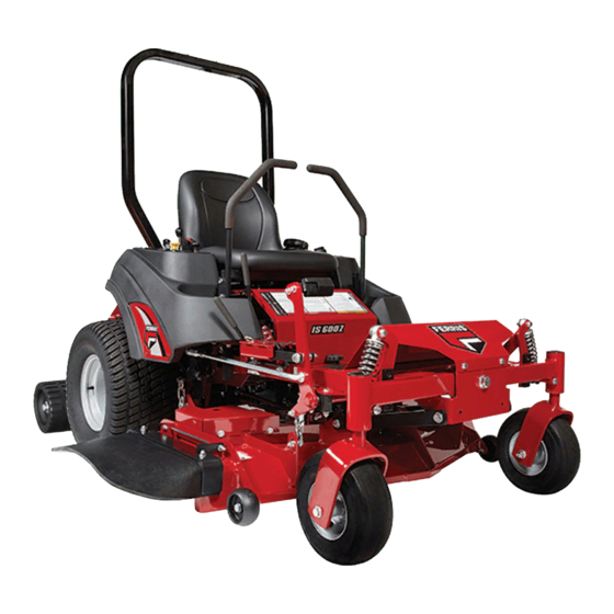
Is500z series zero-turn riding mower
Hide thumbs
Also See for IS500Z Series:
- Operator's manual with setup instructions (44 pages) ,
- Operator's manual (52 pages)
Table of Contents
Advertisement
Briggs & Stratton Power Products Group, LLC.
5375 North Main Street
Munnsville, NY 13409
800-933-6175
Model Number: Description:
5900640
IS500ZB2444
5900704
IS500ZB2652
5900729
IS500ZB2444 AUS/NZ
5900730
IS500ZB2652 AUS/NZ
5900740
IS500ZB2444 CAL
OPERATOR'S
MANUAL
IS500Z Series
Zero-Turn Riding Mower
5100900
Rev: K
Advertisement
Table of Contents
Troubleshooting

Related Manuals for Ferris IS500Z Series


Summary of Contents for Ferris IS500Z Series
- Page 1 OPERATOR’S MANUAL IS500Z Series Zero-Turn Riding Mower Model Number: Description: 5900640 IS500ZB2444 5900704 IS500ZB2652 5900729 IS500ZB2444 AUS/NZ 5900730 IS500ZB2652 AUS/NZ 5900740 IS500ZB2444 CAL Briggs & Stratton Power Products Group, LLC. 5100900 5375 North Main Street Rev: K Munnsville, NY 13409...
- Page 2 Thank you for purchasing this quality-built FERRIS product. We’re pleased that you’ve placed your confidence in the FERRIS brand. When operated and maintained according to the instructions in this manual, your FERRIS product will provide many years of dependable service.
-
Page 3: Table Of Contents
Table of Contents Operator Safety ..........2 Troubleshooting, Adjustments & Service ..30 Identification Numbers ..........11 Troubleshooting the Rider ........30 Safety Decals ............12 Troubleshooting the Mower ........31 Safety Interlock System ........13 Troubleshooting Common Cutting Problems ..32 Seat Adjustment ............33 Features & Controls ......... 14 Ground Speed Control Lever Adjustment .....33 Control Functions ..........14 Speed Balancing Adjustment ........33... -
Page 4: Operator Safety
Operator Safety Operator Safety Operating Safety Congratulations on purchasing a superior-quality piece of lawn and garden equipment. Our products are designed and manufactured to meet or exceed all industry standards for safety. Do not operate this machine unless you have been trained. Reading and understanding this operator’s manual is a way to train yourself. - Page 5 Operator Safety Slope Operation Operation on slopes can be dangerous. Using the unit on a slope that is too steep where you do not have adequate wheel traction (and control) can cause sliding, loss of steering, control, and possible rollover. You should not operate on a slope greater than a 3.5 foot rise over a 20 foot length (10 degrees).
- Page 6 Operator Safety Roll Bar Use Keep the roll bar in position and fasten the seat belt. Do not jump off if the mower tips (it is safer to be secured by the seat belt.) NEVER remove the roll bar. Retaining Walls, Drop-offs, and Water Retaining walls and drop-offs around steps and water are a common hazard.
- Page 7 Operator Safety Fuel and Maintenance Always disengage all drives, shutoff the engine, and remove the key before doing any cleaning, refueling, or servicing. Gasoline and its vapors are extremely flammable. Do not smoke while operating or refueling. Do not add fuel while engine is hot or running.
- Page 8 Operator Safety Read these safety rules and follow them closely. Failure to obey these rules could result in loss of control of unit, severe personal injury or death to you, or bystanders, or damage to property or equipment. This mowing deck is capable of amputating hands and feet and throwing objects. The triangle in text signifies important cautions or warnings which must be followed.
- Page 9 Operator Safety 23. Use care when approaching blind corners, shrubs, Do Not trees or other objects that may obscure vision. 1. Avoid starting, stopping, or turning on a slope. 24. To reduce fire hazard, keep unit free of grass, If tires lose traction (i.e. machine stops forward leaves &...
- Page 10 Operator Safety SERVICE AND MAINTENANCE mufflers, and engine to prevent fires. Clean up oil or fuel spillage. To avoid personal injury or property damage, use 10. Let engine cool before storing and do not store extreme care in handling gasoline. Gasoline is near flame.
- Page 11 Operator Safety 27. Models equipped with an engine radiator: • Never alter the ROLL BAR by welding anything to WARNING: Stored energy device. To prevent it or by drilling additional holes. serious bodily injury from hot coolant or steam • BEFORE FIRST TIME USE - Inspect the ROLL blow-out, never attempt to remove the radiator BAR structure and mounting hardware for: cap while the engine is running.
- Page 12 Operator Safety WARNING INSPECT BUCKLE & LATCH Failure to properly inspect and maintain the seat belt can cause serious injury or death. INSPECTION AND MAINTENANCE OF THE ROLL BAR SEAT BELT • The seat belt like the ROLL BAR, needs to be periodically inspected to verify that the integrity has not been compromised through normal machine use, misuse, age degradation,...
-
Page 13: Identification Numbers
Operator Safety IDENTIFICATION NUMBERS Identification When contacting your authorized dealer for replacement parts, service, or information you MUST have these numbers. Record your part number, serial number and engine serial numbers in the space provided for easy access. These numbers can be found in the locations shown. NOTE: For location of engine identification numbers, refer to the engine owner’s manual. -
Page 14: Safety Decals
Operator Safety SAFETY DECALS This unit has been designed and manufactured to provide you with the safety and reliability you would expect from an industry leader in outdoor power equipment manufacturing. Although reading this manual and the safety instructions it contains will provide you with the necessary basic knowledge to operate this equipment safely and effectively, we have placed several safety labels on the unit to remind you of this important... -
Page 15: Safety Interlock System
Operator Safety SAFETY ICONS SAFETY INTERLOCK The alert symbol is used to identity safety information about hazards that can result in personal SYSTEM injury. A signal word (DANGER, WARNING, or CAUTION) is used with the alert symbol to indicate the likelihood and the potential severity of the injury. This unit is equipped with safety interlock switches. -
Page 16: Features & Controls
Features and Controls Features and Controls Figure 1. Control Locations CONTROL FUNCTIONS The information below briefly describes the function of individual controls. Starting, stopping, driving, and mowing require the combined use of several controls applied in specific sequences. To learn what combination and sequence of controls to use for various tasks see the OPERATION section. - Page 17 Features & Controls Parking Brake Fuel Tank Cap To remove the cap, turn counterclockwise. DISENGAGE Releases the parking brake. ENGAGE Locks the parking brake. Fuel Level Gauge Displays the fuel level in the tank. Pull the parking brake lever back to engage the parking brake.
-
Page 18: Operation
Operation Operation GENERAL OPERATING SAFETY CHECKS BEFORE STARTING Before first time operation: • Check that crankcase is filled to full mark on dipstick. See the engine Operator’s Manual for • Be sure to read all information in the Safety and instructions and oil recommendations. -
Page 19: Starting The Engine
Operation WARNING PUSHING THE RIDER BY HAND If you do not understand how a specific control functions, or have not yet thoroughly read the DO NOT TOW RIDER FEATURES & CONTROLS section, do so now. Towing the unit will cause hydraulic pump Do NOT attempt to operate the tractor without and wheel motor damage. -
Page 20: Zero Turn Driving Practice
Operation Smooth Travel ZERO TURN DRIVING PRACTICE The lever controls of the Zero Turn rider are The lever controls of the Zero Turn rider are responsive. responsive, and learning to gain a smooth and The BEST method of efficient control of the rider’s forward, reverse, and handling the ground turning movements will take some practice. -
Page 21: Advanced Driving
Operation Practice Turning Around a Corner Practice Turning In Place While traveling forward allow one handle to gradually To turn in place, “Zero Turn,” gradually move one return back toward neutral. Repeat several times. ground speed control lever forward from neutral and one lever back from neutral simultaneously. -
Page 22: Mowing
Operation MOWING 1. Engage the parking brake. Make sure the PTO switch is disengaged, the motion control levers are locked in the NEUTRAL position and the operator is on the seat. 2. Start the engine (see STARTING THE ENGINE). 3. Set the mower cutting height. 4. -
Page 23: Mowing Methods
Operation When and How Often to Mow The time of day and condition of the grass greatly affect the results you’ll get when mowing. For the best results, follow these guidelines: 1. Mow when the grass is between three and five inches high. -
Page 24: Attaching A Trailer
Operation Proper Mulching ATTACHING A TRAILER Mulching consists of a mower deck which cuts and The maximum weight of a towed trailer should be recuts clippings into tiny particles and which then less than 200 lbs (91kg). Secure the trailer with a blows them down INTO the lawn. -
Page 25: Storage
Operation STORAGE WARNING Never store the unit, with gasoline in engine Temporary Storage (30 Days Or Less) or fuel tank, in a heated shelter or in enclosed, Remember, the fuel tank will still contain some poorly ventilated enclosures. Gasoline fumes gasoline, so never store the unit indoors or in any may reach an open flame, spark or pilot light other area where fuel vapor could travel to any... -
Page 26: Regular Maintenance
Regular Maintenance Regular Maintenance MAINTENANCE SCHEDULE The following schedule should be followed for normal care of your rider and mower. You will need to keep a record of your operating time. Determining operating time is easily accomplished by observing the elapsed time recorded by the hour meter. -
Page 27: Checking Tire Pressures
Regular Maintenance CHECK TIRE PRESSURES Tire pressure should be checked periodically, and maintained at the levels shown in the chart. Note that these pressures may differ slightly from the “Max Inflation” stamped on the side-wall of the tires. The pressures shown provide proper traction, improve cut quality, and extend tire life. -
Page 28: Lubrication
Figure 15. Deck Lubrication parts to apply grease to moving parts when grease fittings are not installed. Not all greases are compatible. Ferris Red Grease (p/n 5022285) is recommended, automotive-type high-temperature, lithium grease may be used when this is not available. -
Page 29: Check Hydraulic Oil Level
NOTE: Removing the oil filter from the filter base will drain the oil reservoir. Have a suitable container ready to catch any spilled oil. Ferris recommends this be a dealer-only service item. 1. Locate the transmission oil filter (E, Figure 20) at the rear of the battery compartment under the seat. -
Page 30: Servicing The Mower Blades
Regular Maintenance SERVICING THE MOWER BLADES Removing the Mower Blade CAUTION Avoid injury! Mower blades are sharp. • Always wear gloves when handling mower blades or working near blades. 1. See Figure 21. To remove the mower blade, wedge a wooden block between the mower blade and the mower deck housing to keep the mower blade from turning, then remove the mower blade and the mower blade retaining hardware. - Page 31 Regular Maintenance Sharpening the Mower Blade CAUTION Avoid injury! Mower blades are sharp. • Always wear gloves when handling the mower blades. • Always wear safety eye protection when grinding. Figure 24. Sharpening the Mower Blade 1. Sharpen the mower blades with grinder, hand file, A.
-
Page 32: Troubleshooting, Adjustments & Service
Troubleshooting, Adjustment & Service Troubleshooting TROUBLESHOOTING CHART WARNING While normal care and regular maintenance will To avoid serious injury, perform maintenance extend the life of your equipment, prolonged or on the tractor or mower only when the engine constant use may eventually require that service be is stopped and the parking brake engaged. -
Page 33: Troubleshooting The Mower
Troubleshooting, Adjustment & Service Rider Troubleshooting Continued. PROBLEM CAUSE REMEDY Engine runs, but rider will 1. Hydraulic release valve(s) 1. Turn valve(s) clockwise to close. not drive. in “open” position. 2. Belt is broken. 2. See Drive Belt Replacement. 3. Drive belt slips. 3. -
Page 34: Troubleshooting Common Cutting Problems
Troubleshooting, Adjustment & Service TROUBLESHOOTING COMMON CUTTING PROBLEMS PROBLEM CAUSE REMEDY Streaking. 1. Blades are not sharp. 1. Sharpen your blades. 2. Blades are worn down to far. 2. Replace your blades. 3. Engine speed is too slow. 3. Always mow at full throttle. 4. -
Page 35: Seat Adjustment
Troubleshooting, Adjustment & Service SEAT ADJUSTMENT See Figure 27. The seat can be adjusted forward and backward. Move the lever towards the left, position the seat as desired, and release the lever to lock the seat into position. GROUND SPEED CONTROL LEVER ADJUSTMENT The control levers can be adjusted in three ways. -
Page 36: Parking Brake Adjustment
Figure 30. Parking Brake Adjustment A. Brake Spring Do not adjust the spring to be shorter than B. Adjustment Nut 1-15/16” (4,9 cm) when compressed. This may damage the brake mechanism. If this does not correct the braking problem, see your Ferris dealer. www.ferrisindustries.com... -
Page 37: Rear Suspension Adjustment
Troubleshooting, Adjustment & Service REAR SUSPENSION ADJUSTMENT The shock assembly can be adjusted to allow the operator to customize the ride according to operator’s weight and/or operating conditions. You have the option of adjusting the spring pre-load. Items to consider before adjusting the suspension. •... -
Page 38: Return To Neutral Adjustment
Troubleshooting, Adjustment & Service RETURN-TO-NEUTRAL ADJUSTMENT To determine if it is necessary to adjust the neutral 3.25” return, perform the following steps. (8,23cm) 1. Disengage the PTO, engage the parking brake and turn off the engine. 2. Move the ground speed control levers into the operating position, pull levers rearward and release. -
Page 39: Neutral Adjustment
Troubleshooting, Adjustment & Service NEUTRAL ADJUSTMENT If the tractor “creeps” while the ground speed control levers are locked in NEUTRAL, then it may be necessary to adjust the linkage rod. NOTE: Perform this adjustment on a hard, level surface such as a concrete floor. 1. -
Page 40: Deck Lift Rod Timing Adjustment
Troubleshooting, Adjustment & Service DECK ROD TIMING ADJUSTMENT 1. Park machine on a flat, level surface. Disengage the PTO, stop the engine and engage the parking brake. Rear tires must be inflated to 15 psi (1,03 bar); front tires to 25 psi (1,72 bar). 2. -
Page 41: Deck Leveling Adjustment
Troubleshooting, Adjustment & Service DECK LEVELING ADJUSTMENT 44” & 52” Models NOTE: Before adjusting the deck level, the deck lift rod timing must be checked and/or adjustment. 1. Park machine on a flat, level surface. Disengage the PTO, stop the engine and engage the parking brake. -
Page 42: Mower Belt Replacement
Troubleshooting, Adjustment & Service MOWER BELT REPLACEMENT 44” Deck To avoid damaging belts, DO NOT PRY BELTS OVER PULLEYS. 1. Park the tractor on a smooth, level surface such as a concrete floor. Disengage the PTO, engage the parking brake, turn off the engine, and remove the ignition key. -
Page 43: Check Mower Belt Tensioner Spring Length
Troubleshooting, Adjustment & Service Check the Mower Belt Tensioner Spring Length With the spring anchor (A, Figure 42) adjusted in the 7-1/4” second hole (B) of the spring bracket (C) the coil-to- (18,42 cm) coil spring length should measure 7-1/4” (18,42 cm). Figure 42. -
Page 44: Battery Service
Troubleshooting, Adjustment & Service fully charged, but not over charged, is to measure BATTERY SERVICE the specific gravity of a cell once per hour. The battery is fully charged when the cells are gassing WARNING freely at low charging rate and less than 0.003 Keep open flames and sparks away from the change in specific gravity occurs over a three hour battery;... - Page 45 Troubleshooting, Adjustment & Service THIS HOOK-UP FOR NEGATIVE GROUND VEHICLES Starter Starter Switch Switch Jumper Cable Starting Discharged Vehicle Vehicle Battery Battery Jumper Cable To Ground Engine Block MAKE CERTAIN VEHICLES DO NOT TOUCH Figure 44. Jump Starting WARNING WARNING Any procedure other than the preceding could For your personal safety, use extreme care result in:...
-
Page 46: Specifications
Specifications Specifications NOTE: Specifications are correct at time of printing and are subject to change without notice. ENGINE TRANSMISSIONS 24 Gross HP* Briggs & Stratton (S/N: 2012944927 & Below): Make Briggs & Stratton PG-1HQQ-DV1X-XXXX (5100072) HGM-12C-4025 (5023316) Model 44M777-0133-E1 (S/N: 2012998559 & Below) 44M777-0133-G1 (S/N: 2012998560 &... -
Page 47: Slope Identification Guide
ALIGN THIS EDGE WITH A VERTICAL SURFACE (TREE, POLE, FENCE POST, BUILDING, ETC) - Page 48 Notes...
- Page 49 Notes...
- Page 51 Ferris dealer during the warranty period. Ferris’ obligation under this limited warranty is, at Ferris’ option, to repair or replace any part or parts of the mower, which, in the judgment of Ferris, are found to be defective and covered by this limited warranty.
- Page 52 OPERATOR’S MANUAL IS500Z Series Zero-Turn Riding Mower Briggs & Stratton Power Products Group, LLC. 5375 North Main Street Munnsville, NY 13409 800-933-6175 www.ferrisindustries.com...