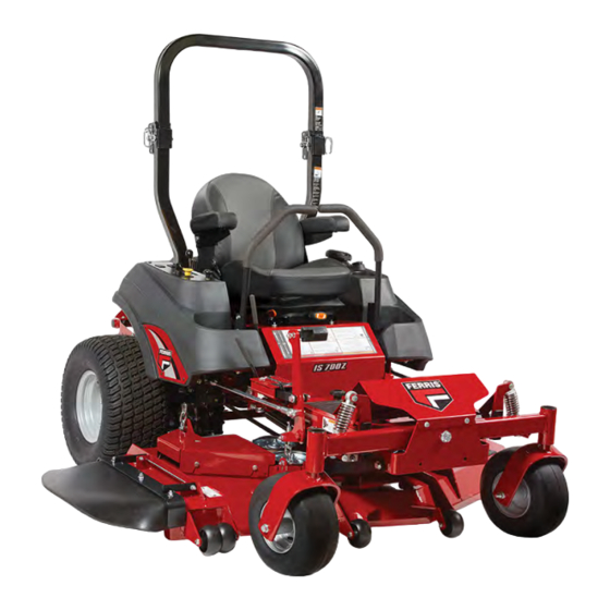
Ferris IS700Z Series Operator's Manual
Zero-turn riding mower
Hide thumbs
Also See for IS700Z Series:
- Operator's manual (44 pages) ,
- Dealer setup & adjustment instructions manual (17 pages)
Table of Contents
Advertisement
Advertisement
Table of Contents
Troubleshooting

Related Manuals for Ferris IS700Z Series


Summary of Contents for Ferris IS700Z Series
-
Page 2: Table Of Contents
Table of Contents: Seat Adjustment (Suspension Seat)......33 Ground Speed Control Lever Adjustment...... 33 General Information.............. 3 Speed Balancing Adjustment......... 34 Identifying Your Unit ............3 Checking Tire Pressures..........34 Operator Safety..............3 Cutting Height Adjustment..........34 Safety Alert Symbol and Signal Words......3 Foot Pedal Adjustment........... -
Page 3: General Information
Your unit may vary from the images displayed. LEFT and RIGHT are as seen from the operator's PRODUCT REFERENCE DATA position. Unit Model Number: FERRIS is a registered trademark of Briggs & Stratton. Unit Serial Number: Mower Deck Model Number (if Identifying Your Unit applicable):... -
Page 4: California Proposition 65
Read the Manual CAUTION indicates a hazard which, if not avoided, could result in minor or moderate injury. NOTICE indicates information considered important but not hazard-related. California Proposition 65 WARNING This product can expose you to chemicals including gasoline engine exhaust, which is known to the State of The operator’s manual contains important safety information California to cause cancer and carbon monoxide, which you need to be aware of BEFORE you operate your unit as... - Page 5 operate on a slope greater than 15 degrees (a 5.4 foot rise attempt to alter or bypass the system. See your dealer over a 20 foot length). immediately if the system does not pass all the safety interlock system tests found in this manual. Avoid turning down slopes;...
-
Page 6: Slope Identification Guide
Slope Identification Guide Check for overhead clearances before driving under any objects. Do not allow the roll bar to contact low overhanging obstacles such as tree branches and guide wires. Fuel and Maintenance Always disengage all drives, shutoff the engine, and remove the key before doing any cleaning, refueling, or servicing. ... - Page 7 Training conditions can affect the machines stability. Use caution when operating near drop-offs. • Read, understand, and follow all instructions in the • Do not mow in reverse unless absolutely necessary. manual and on the unit before starting. If the operator(s) Always look down, behind and to the side before or mechanic(s) can not read English it is the owner’s changing directions. ...
- Page 8 • OSHA regulations may require the use of hearing • Do not use grass catcher on steep slopes. protection when exposed to sound levels greater than 85 • Do not mow slopes if you cannot back up them. dBA for an 8 hour time period. Towed Equipment (Ride-On Units) CAUTION •...
- Page 9 • Never fill containers inside a vehicle or on a truck bed first and the positive last. Reconnect positive first and with a plastic bed liner. Always place containers on the negative last. ground away from your vehicle before filling. •...
- Page 10 Roll Bar Instructions • EVERY 100 HOURS - Inspect the ROLL BAR structure and mounting hardware for: For models equipped with factory-installed Roll Over 1) Any cracks in the structure (structural members and/or Protection System (ROPS). welds). 2) Significant corrosion on any part of the ROLL BAR WARNING structure or hardware.
-
Page 11: Safety Decals And Icons (North American Models)
1) Check for dirt or debris in the retraction mechanism. If E. Part Number: 5104082YP - Decal, Warning, Folding Roll Bar dirt or debris is found, it should be removed. F. Part Number: 5104083YP - Decal, Caution, Folding 2) Check to make sure the retraction mechanism retracts Roll Bar easily and completely. ... - Page 12 DANGER DANGER Amputation hazard. Wet or soft slope hazard. Rotating blades cut off arms and legs. Wet or soft slopes can cause sliding and loss of control. • Stop the mower when children or others are • Do NOT operate on slopes when grass is wet. near. Keep bystanders away.
-
Page 13: Safety Decals And Icons (Export Models)
Decal, Warning, Pinch Point Decal, Caution, Folding Roll Bar Part Number: 84008198 Part Number: 5104083YP WARNING Roll Over Protective Structure. To maintain operator protection and roll bar certification: • Replace a damaged roll bar, do not attempt to repair or modify. •... - Page 14 Danger - Amputation and dismemberment hazard: To avoid injury from rotating blades and moving parts, keep safety devices (guards, shields and switches) in place and working. Danger - Loss of traction, sliding, steering and control on slopes hazard: If machine stops forward motion, stop the blades, and drive slowly off the slope.
- Page 15 Danger - Thrown Objects Hazard: Do not mow without discharge chute or entire grass catcher in place. Danger - Amputation and Thrown Objects Hazard: To avoid injury from rotating blades, stay clear of deck edge and keep others away. 5061246 - Decal, Pinch Point Warning: Fire Hazard - Keep children, open flames and sparks away from the battery, which could ignite explosive gases.
-
Page 16: Safety Icons For Optional Jack Kit Accessory
Test 2 - Engine SHOULD crank if: Warning: Avoid Serious Injury or Death • PTO switch is not engaged, AND from Roll Over - Keep roll bar in the raised position and use seat belt. There is no roll • Parking brake is engaged. over protection when roll bar is down. - Page 17 A. Deck Lift Pedal B. Cutting Height Adjustment Pin C. Deck Lift Lock Lever D. Ground Speed Control Levers E. Fuel Level Gauge F. Parking Brake Lever G. Suspension Seat H. Roll Bar Seat Latch J. Fuel Tank Cap K. Removable Floor Plate L. Transmission Oil Fill/Tanks (One per transmission) M.
-
Page 18: Suspension Seat
DISENGAGE: Releases the ENGAGE: Locks the parking parking brake. brake. Suspension Seat Some models are equipped with a suspension seat. This seat has several additional options. See Figure 9 and the list below for the location of the seat's features and brief description of their function. -
Page 19: Instrument Control Panel
Instrument Control Panel Fast throttle speed. Slow throttle speed. Hour Meter: This unit is equipped with a dual function hour meter that records the number of hours that the engine has run and the number of hours that the PTO switch has been engaged. -
Page 20: Before First Time Operation
Before First Time Operation • Make sure all nuts, bolts, screws, and pins are in place and tight. • Be sure to read all information in the Safety and • Adjust the seat position and make certain you can reach Operation sections before attempting to operate this all the controls from operator’s position. - Page 21 section and understand the location and function of all the THIRD, to speed up move the levers farther forward. To slow unit's controls. down smoothly, slowly move the levers toward neutral. The ground speed control levers of the zero-turn riding mower Basic Driving are responsive and learning to gain a smooth and efficient Forward Travel Practice...
-
Page 22: Mowing
Your zero-turn riding mower's unique ability to turn in place While traveling forward allow one ground speed control lever allows you to turn around at the end of a cutting row rather to gradually return back toward neutral. Repeat several times. than having to stop and Y-turn before starting a new row. - Page 23 Height of Grass Often cutting height is a matter of personal preference. Typically, you should mow the grass when it is between three and five inches high. The proper cutting height range for a specific lawn will depend upon several factors, including the type of grass, the amount of rainfall, the prevailing temperature, and the lawn’s overall condition.
-
Page 24: Pushing The Unit By Hand
Mulching Mulching consists of a mower deck which cuts and re-cuts clippings into tiny particles and which then blows them down INTO the lawn. These tiny particles decompose rapidly into by-products your lawn can use. UNDER PROPER CONDITIONS, your mulching mower will virtually eliminate noticeable clippings on the lawn surface. -
Page 25: Raise And Lower The Roll Bar
rear wheels on the transmission cradle (B). There is 1. Pull the hair pin clips (A, Figure 23) out of the retainer one transmission release lever on each transmission. pins (B). The transmission release levers open and close the transmission bypass valves. 3. -
Page 26: Attaching A Trailer
Attaching a Trailer • Park the unit on a flat level surface. Disengage the PTO, engage the parking brake, turn the ignition switch to OFF, The maximum weight of a towed trailer should be less than and remove the ignition key. 200 lbs (91kg). -
Page 27: Maintenance Schedule
ENGINE MAINTENANCE 1. Remove any blocks from under the unit. Check/Replace Fuel Filter 2. Install the battery if it was removed. *More often in hot (over 85°F, 30°C) weather or dusty operating 3. Unplug the exhaust outlet and air cleaner. conditions. -
Page 28: Replacing The Fuel Filter
Check Engine Oil Level Interval: Before Each Use Refer to the engine operator's manual for dipstick and oil fill locations and specific engine oil check and fill procedures. Changing the Engine Oil and Filter This series of mower has different engine options: Briggs & Stratton Commercial Turf series (A, Figure 26) or Briggs &... -
Page 29: Inspect Muffler And Spark Arrester
Inspect Muffler and Spark Arrester 6. After adding oil to the tanks, it may be necessary to purge air from the hydraulic system. If the unit is not driving Inspect the muffler for cracks, corrosion, or other damage. properly perform the Purging the Air from the Hydraulic Remove the spark arrester, if equipped, and inspect System procedure. -
Page 30: Purging The Air From The Hydraulic System
2. Remove the three 1/4” filter guard screws (C) and the 2. Open the transaxle’s bypass valves (see Pushing the filter guard (B). Unit by Hand for the location and function of the bypass valves), start the engine, release the parking brake, and 3. -
Page 31: Lubricate The Front Casters
1. Remove the 1/4-28 bolt (A, Figure 33) screwed into the caster and install a 1/4-28 grease fitting. 2. Grease the front caster. 3. Remove the 1/4-28 grease fitting and reinstall the 1/4-28 bolt. 4. Repeat the process for the other side of the machine. Servicing the Mower Blades Removing the Mower Blades CAUTION... - Page 32 Inspecting, Sharpening, and Balancing the 4. If the cutting edges are not sharp or have nicks, sharpen the blades. Mower Blades CAUTION WARNING Laceration hazard. Thrown objects and fire hazard Mower blades are sharp. Grinding mower blades throws sparks and fine metal particles that are capable of igniting gasoline and gasoline Always wear gloves when handling, or working near, mower vapors, and that can injure unprotected eyes.
-
Page 33: Seat Adjustment (Suspension Seat)
9. Check the balance of the blade. If either end of the the seat as desired, and release the lever to lock the seat in blade moves downward the end that moves downward position. Suspension Seat Adjustment is heavier than the other. Sharpen the heavy end until balance is achieved. -
Page 34: Speed Balancing Adjustment
Cutting Height Adjustment Loosen the jam nuts and adjust the placement bolt (B) in or out to properly adjust the control lever end spacing. The cutting height adjustment pin (A, Figure 42) controls the mower's cutting height. The cutting height is adjustable To Adjust the Control Lever Height between 1-1/2"... -
Page 35: Foot Pedal Adjustment
2. Place the cutting height adjustment pin in any open cutting height hole. The lift lock lever holds the mower deck at 5" (12,7 cm) while cutting. Foot Pedal Adjustment The deck lift foot pedal can be adjusted to accommodate the operator’s height for optimal comfort. -
Page 36: Return-To-Neutral Adjustment
achieved by changing the length of the upper rod (A, Figure 46) that connects the ground speed control lever to the pivot. 3. Position the set collar along the neutral return rod until it contacts and very lightly compresses the neutral return Determining if Adjustment is Necessary: If the unit spring (C). -
Page 37: Parking Brake Adjustment
If this does not correct the braking problem, see your the parking brake cables and the compressed length of the authorized FERRIS servicing dealer. lower springs located by the transmissions are factory preset and should not be changed for parking brake adjustment Deck Lift Rod Timing Adjustment procedures. -
Page 38: Deck Leveling Adjustment
• Turn the ball joint clockwise to shorten the distance 3. If the measurements for the rods are equal, no further between the rod pivots; adjustment is required. If the measurements are not equal • Turn the ball joint counter-clockwise to lengthen the (greater than 1/8"... -
Page 39: Deck Lift Assist Springs
• If the mower deck does not measure 4" (10,2 cm) in the front and 4-1/4" (10,8 cm) in the rear, proceed with step #8. 8. Loosen the jam nut (A) and turn the fine adjustment bolt (B) to adjust the deck height. •... - Page 40 • 52" Mower Decks: Rotate the idler arm clockwise so that it is pulled away from the idler arm stop (L, Figure 56). To remove the belt from the belt guide, start with the leg of the belt between the adjustable idler pulley and the PTO clutch pulley (G) and press the belt down below the belt guide and then pull it around and then above the belt guide.
-
Page 41: Transmission Drive Belt Replacement
Mower Deck Drive Belt Tensioning Spring Length Deck Size Measurement 52" 12" (30,5 cm) 60" / 61" 12" (30,5 cm) 13. Measure the coil length (A, Figure 58) of the mower belt idler tensioning spring (B). The measurement should equal the measurement as indicated in the chart. If not, continue with step #4. -
Page 42: Rear Suspension Adjustment
and/or operating conditions. You have the option of adjusting the spring pre-load and/or the upper mounting position. Items to consider before adjusting the suspension. • Less spring pre-load should be used with light weight operators, which will provide a softer, more cushioned ride. -
Page 43: Battery Maintenance
Keep the battery out of reach of children. If there is any doubt about the cause of the problem, see your authorized FERRIS servicing dealer. If you need to replace To avoid an explosion, keep open flames and sparks away the battery, follow the steps under Cleaning the Battery and from the battery, especially while charging. -
Page 44: Troubleshooting
Troubleshooting Problem: Engine starts hard or runs poorly. Spark plug(s) faulty, fouled, or Clean and gap, or replace. See While normal care and regular maintenance will extend incorrectly gapped. engine operator's manual. the life of your equipment, prolonged or constant use may eventually require that service be performed to allow it to Problem: Engine knocks. -
Page 45: Troubleshooting Common Cutting Problems
Problem: Engine stalls easily with mower engaged. Problem: Scalping Cause Remedy Scalping is when the mower deck comes close to or hits the ground. Scalping can be caused by the mower deck misadjustment, unevenness in Engine speed too slow. Set to full throttle. the lawn, or by mower deck bouncing because the ground speed is too fast. -
Page 46: Specifications
Problem: Stringers Reverse 0-5 mph (0-8 km/h) Stringers are sparse patches of uncut grass left behind the mower. DIMENSIONS Stringers are usually caused by operator error or poor blade maintenance. Models with 52" Mower Decks Overall Length 81" (206 cm) Overall Width (with discharge 66-3/4"... - Page 47 Product registration is not required to obtain warranty service on Briggs & Stratton products. ABOUT YOUR WARRANTY Warranty service is available only through FERRIS Authorized Service Dealers. This warranty only covers defects in materials or workmanship. It does not...