Table of Contents
Advertisement
Model Number:
5900619
5901170
5900624
5900625
5900629
5900670
5900713
5900714
5900715
5900737
5900738
5900750
5900754
Briggs & Stratton Power Products Group, LLC.
5375 North Main Street
Munnsville, NY 13409
800-933-6175
Description
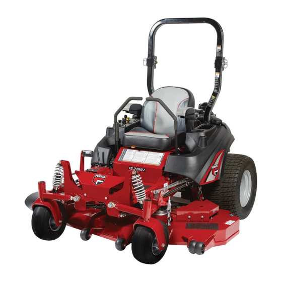
IS2000ZKAV2561, 25HP, 61" Cut Zero-Turn Riding Mower
IS2000ZK2761, 27HP, 61" Cut Zero-Turn Riding Mower
IS2000ZKAV2552, 25HP, 52" Cut Zero-Turn Riding Mower
IS2000ZK2752, 27HP, 52" Cut Zero-Turn Riding Mower
IS2000ZLKAV2661, 26HP, 61" Cut Zero-Turn Riding Mower
IS2000ZBV3061, 30HP, 61" Cut Zero-Turn Riding Mower
IS2000ZKAV25/52 AUS/NZ, 25HP, 52" Cut Zero-Turn Riding Mower
IS2000ZKAV25/61 AUS/NZ, 25HP, 61" Cut Zero-Turn Riding Mower
IS2000ZBV30/61 AUS/NZ, 30HP, 61" Cut Zero-Turn Riding Mower
IS2000ZKAV2561 CAL, 25HP, 61" Cut Zero-Turn Riding Mower
IS2000ZBV3061 CAL, 30HP, 61" Cut Zero-Turn Riding Mower
IS2000ZKAV2761, 27HP, 61" Cut Zero-Turn Riding Mower
IS2000ZKAV3461SS, 34HP, 61" Cut Zero-Turn Riding Mower
OPERATOR'S
MANUAL
IS2000Z Series
Zero-Turn Riding Mower
5100758
Revision G
Rev. Date: 05/2008
TP 100-7299-G-2Z-F
Advertisement
Table of Contents
Troubleshooting

Related Manuals for Ferris 5900619


Summary of Contents for Ferris 5900619
- Page 1 OPERATOR’S MANUAL IS2000Z Series Zero-Turn Riding Mower Model Number: Description 5900619 IS2000ZKAV2561, 25HP, 61” Cut Zero-Turn Riding Mower 5901170 IS2000ZK2761, 27HP, 61” Cut Zero-Turn Riding Mower 5900624 IS2000ZKAV2552, 25HP, 52” Cut Zero-Turn Riding Mower 5900625 IS2000ZK2752, 27HP, 52” Cut Zero-Turn Riding Mower 5900629 IS2000ZLKAV2661, 26HP, 61”...
- Page 2 Thank you for purchasing this quality-built Ferris product. We’re pleased that you’ve placed your confidence in the Ferris brand. When operated and maintained according to the instructions in this manual, your Ferris product will provide many years of dependable service.
-
Page 3: Table Of Contents
Table of Contents Operator Safety ...........2 Identification Numbers ..........11 Safety Decals ............12 Safety Interlock System ........13 Features & Controls ..........14 Control Functions..........14 Control Functions - Liquid Cooled Model .....16 Operation ............18 General ..............18 Checks Before Starting .........18 Starting the Engine ..........19 Stopping the Rider ..........19 Pushing the Rider by Hand........19 Zero Turn Driving Practice ........20... -
Page 4: Operator Safety
Operator Safety Operating Safety Congratulations on purchasing a superior-quality piece of lawn and garden equipment. Our products are designed and manufactured to meet or exceed all industry standards for safety. Do not operate this machine unless you have been trained. Reading and understanding this operator’s manual is a way to train yourself. -
Page 5: Slope Operation
Operator Safety Slope Operation Operation on slopes can be dangerous. Using the unit on a slope that is too steep where you do not have adequate wheel traction (and control) can cause sliding, loss of steering, control, and possible rollover. You should not operate on a slope greater than a 5.4 foot rise over a 20 foot length (15 degrees). - Page 6 Operator Safety Roll Bar Use Keep the roll bar in the raised position and fasten the seat belt. There is no roll over protection when the roll bar is down! Do not jump off if the mower tips (it is safer to be secured by the seat belt with the roll bar raised.) Lower the roll bar only when necessary (such as to...
- Page 7 Operator Safety Fuel and Maintenance Always disengage all drives, shutoff the engine, and remove the key before doing any cleaning, refueling, or servicing. Gasoline and its vapors are extremely flammable. Do not smoke while operating or refueling. Do not add fuel while engine is hot or running.
- Page 8 Operator Safety Read these safety rules and follow them closely. Failure to obey these rules could result in loss of control of unit, severe personal injury or death to you, or bystanders, or damage to property or equipment. This mowing deck is capable of amputating hands and feet and throwing objects. The triangle in text signifies important cautions or warnings which must be followed.
- Page 9 Operator Safety 23. Use care when approaching blind corners, shrubs, Do Not trees or other objects that may obscure vision. 1. Avoid starting, stopping, or turning on a slope. If 24. To reduce fire hazard, keep unit free of grass, tires lose traction (i.e.
- Page 10 Operator Safety IGNITION SYSTEM (GASOLINE MODELS) 8. Disengage drives, lower implement, set parking brake, stop engine and remove key or disconnect 1. This spark ignition system complies with Canadian spark plug wire. Wait for all movement to stop ICES-002. before adjusting, cleaning or repairing. 9.
- Page 11 Operator Safety 27. Models equipped with an engine radiator: • Never alter the ROLL BAR by welding anything to WARNING: Stored energy device. To prevent it or by drilling additional holes. serious bodily injury from hot coolant or steam • BEFORE FIRST TIME USE - Inspect the ROLL blow-out, never attempt to remove the radiator cap BAR structure and mounting hardware for: while the engine is running.
- Page 12 Operator Safety WARNING INSPECT BUCKLE & LATCH Failure to properly inspect and maintain the seat belt can cause serious injury or death. INSPECTION AND MAINTENANCE OF THE ROLL BAR SEAT BELT • The seat belt like the ROLL BAR, needs to be periodically inspected to verify that the integrity has not been compromised through normal machine use, misuse, age degradation,...
-
Page 13: Identification Numbers
Operator Safety Identification Numbers Identification When contacting your authorized dealer for replacement parts, service, or information you MUST have these numbers. Record your part number, serial number and engine serial numbers in the space provided for easy access. These numbers can be found in the locations shown. NOTE: For location of engine identification numbers, refer to the engine owner’s manual. -
Page 14: Safety Decals
Operator Safety SAFETY DECALS This unit has been designed and manufactured to provide you with the safety and reliability you would expect from an industry leader in outdoor power equipment manufacturing. Although reading this manual and the safety instructions it contains will provide you with the necessary basic knowledge to operate this equipment safely and effectively, we have placed several safety labels on the unit to remind you of this important... -
Page 15: Safety Interlock System
Operator Safety Safety Icons SAFETY INTERLOCK The alert symbol is used to identity safety information about hazards that can result in personal SYSTEM injury. A signal word (DANGER, WARNING, or CAUTION) is used with the alert symbol to indicate This unit is equipped with safety interlock switches. the likelihood and the potential severity of the injury. -
Page 16: Features & Controls
Features & Controls AIR COOLED MODELS ONLY CONTROL FUNCTIONS The information below briefly describes the function of individual controls. Starting, stopping, driving, and mowing require the combined use of several controls applied in specific sequences. To learn what combination and sequence of controls to use for various tasks see the OPERATION section. Ground Speed Levers Seat Adjustment Lever These levers control the ground speed of the rider. - Page 17 Features & Controls Parking Brake Fuel Tank Cap To remove the cap, turn counterclockwise. DISENGAGE Releases the parking brake. Fuel Level Gauge ENGAGE Locks the parking brake. Displays the fuel level in the tank. Pull the parking brake lever back to engage the parking brake.
-
Page 18: Control Functions - Liquid Cooled Model
Features & Controls LIQUID COOLED MODELS ONLY CONTROL FUNCTIONS The information below briefly describes the function of individual controls. Starting, stopping, driving, and mowing require the combined use of several controls applied in specific sequences. To learn what combination and sequence of controls to use for various tasks see the OPERATION section. Ground Speed Levers Seat Adjustment Lever These levers control the ground speed of the rider. - Page 19 Features & Controls Parking Brake Fuel Tank Cap To remove the cap, turn counterclockwise. DISENGAGE Releases the parking brake. Fuel Level Gauge ENGAGE Locks the parking brake. Displays the fuel level in the tank. Pull the parking brake lever back to engage the parking brake.
-
Page 20: Operation
Operation CHECKS BEFORE STARTING GENERAL OPERATING SAFETY • Check that crankcase is filled to full mark on Before first time operation: dipstick. See the engine Operator’s Manual for • Be sure to read all information in the Safety and instructions and oil recommendations. Operation sections before attempting to operate •... -
Page 21: Starting The Engine
Operation PUSHING THE RIDER BY HAND WARNING DO NOT TOW RIDER If you do not understand how a specific control Towing the unit will cause hydraulic pump functions, or have not yet thoroughly read the and wheel motor damage. Do not use FEATURES &... -
Page 22: Zero Turn Driving Practice
Operation ZERO TURN Smooth Travel DRIVING PRACTICE The lever controls of the Zero Turn rider are The lever controls of the Zero Turn rider are responsive. responsive, and learning to gain a smooth and The BEST method of efficient control of the rider’s forward, reverse, and handling the ground turning movements will take some practice. -
Page 23: Advanced Driving
Operation Practice Turning Around a Corner Practice Turning In Place While traveling forward allow one handle to gradually To turn in place, “Zero Turn,” gradually move one return back toward neutral. Repeat several times. ground speed control lever forward from neutral and one lever back from neutral simultaneously. -
Page 24: Mowing
Operation MOWING 1. Engage the parking brake. Make sure the PTO switch is disengaged, the motion control levers are locked in the NEUTRAL position and the operator is on the seat. 2. Start the engine (see STARTING THE ENGINE). 3. Set the mower cutting height. 4. -
Page 25: Mowing Methods
Operation When and How Often to Mow The time of day and condition of the grass greatly affect the results you’ll get when mowing. For the best results, follow these guidelines: 1. Mow when the grass is between three and five inches high. -
Page 26: Attaching A Trailer
Operation Proper Mulching ATTACHING A TRAILER Mulching consists of a mower deck which cuts and The maximum weight of a towed trailer should be less recuts clippings into tiny particles and which then than 200 lbs (91kg). Secure the trailer with a blows them down INTO the lawn. -
Page 27: Raise & Lower The Roll Bar
Operation RAISE & LOWER THE ROLL BAR To lower the roll bar: 1. Pull the hair pin clips (A, Figure 13) out of the retainer pins (B). 2. Push or pull the top of the roll bar (C) forward against the rubber stops (D) and remove the retainer pins (B). -
Page 28: Storage
Operation STORAGE WARNING Temporary Storage (30 Days Or Less) Never store the unit, with gasoline in engine or fuel tank, in a heated shelter or in enclosed, Remember, the fuel tank will still contain some poorly ventilated enclosures. Gasoline fumes gasoline, so never store the unit indoors or in any may reach an open flame, spark or pilot light other area where fuel vapor could travel to any... -
Page 29: Regular Maintenance
Regular Maintenance MAINTENANCE SCHEDULE The following schedule should be followed for normal care of your rider and mower. You will need to keep a record of your operating time. Determining operating time is easily accomplished by observing the elapsed time recorded by the hour meter. -
Page 30: Checking Tire Pressures
Regular Maintenance CHECK TIRE PRESSURES Tire pressure should be checked periodically, and maintained at the levels shown in the chart. Note that these pressures may differ slightly from the “Max Inflation” stamped on the side-wall of the tires. The pressures shown provide proper traction, improve cut quality, and extend tire life. -
Page 31: Check Hydraulic Oil Level
NOTE: Removing the oil filter from the filter base will drain the oil reservoir. Have a suitable container ready to catch any spilled oil. Ferris recommends this be a dealer-only service item. 1. Locate the transmission oil filter (A, Figure 17). -
Page 32: Check Engine Coolant Level
Regular Maintenance CHECK ENGINE COOLANT LEVEL WARNING The engine coolant level and quality should be PRESSURIZED SYSTEM checked before each use, when the engine is cool Hot coolant can cause serious burns. Never and off. open the radiator cap. Wait until the engine is The cooling system is a closed type. -
Page 33: Lubrication
Use grease fittings when present. Disassemble parts Pivots to apply grease to moving parts when grease fittings are not installed. Not all greases are compatible. Ferris Red Grease (p/n 5022285) is recommended, automotive-type high-temperature, lithium grease may be used when this is not available. -
Page 34: Battery Maintenance
Regular Maintenance BATTERY MAINTENANCE Air Cooled Models NOTE: This unit is equipped with a maintenance-free BCIU1 battery. Cleaning the Battery and Cables - Air Cooled Models. 1. Remove the hydraulic oil reservoir mounting hardware (C, Figure 24) and move the reservoir (D) forward to expose the battery. -
Page 35: Servicing The Mower Blades
Regular Maintenance SERVICING THE MOWER BLADES 1. Blades should be sharp and free of nicks and dents. If not, sharpen blades as described in the following steps. 2. To remove blade for sharpening, use a 1” wrench on the flats of the spindle shaft while removing the blade mounting bolt with a 15/16”... -
Page 36: Troubleshooting, Adjustments & Service
Troubleshooting, Adjustment & Service TROUBLESHOOTING WARNING While normal care and regular maintenance will To avoid serious injury, perform maintenance extend the life of your equipment, prolonged or on the tractor or mower only when the engine constant use may eventually require that service be is stopped and the parking brake engaged. -
Page 37: Troubleshooting The Mower
Troubleshooting, Adjustment & Service RIDER TROUBLESHOOTING CONTINUED. PROBLEM CAUSE REMEDY Engine runs, but rider will 1. Hydraulic release valve(s) 1. Turn valve(s) clockwise to close. not drive. in “open” position. 2. Belt is broken. 2. See Drive Belt Replacement. 3. Drive belt slips. 3. -
Page 38: Troubleshooting Common Cutting Problems
Troubleshooting, Adjustment & Service TROUBLESHOOTING COMMON CUTTING PROBLEMS PROBLEM CAUSE REMEDY Streaking. 1. Blades are not sharp. 1. Sharpen your blades. 2. Blades are worn down to far. 2. Replace your blades. 3. Engine speed is too slow. 3. Always mow at full throttle. 4. -
Page 39: Seat Adjustment
Troubleshooting, Adjustment & Service SEAT ADJUSTMENT See Figure 28. The seat can be adjusted forward and back. Move the lever forward, position the seat as desired, and release the lever to lock the seat into Seat Adjustment position. Lever SEAT ADJUSTMENT (SUSPENSION SEAT) See Figure 29. -
Page 40: Speed Balancing Adjustment
Troubleshooting, Adjustment & Service SPEED BALANCING ADJUSTMENT If the rider veers to the right or left when the ground speed control levers are in the maximum forward position, the top speed of each of these levers can be balanced by turning the adjustment bolt(s) (A, Figure 31). -
Page 41: Return To Neutral Adjustment
Figure 34. Parking Brake Adjustment A. Brake Spring Do not adjust the spring to be shorter than B. Adjustment Nut 1-15/16” (4,9 cm) when compressed. This may damage the brake mechanism. If this does not correct the braking problem, see your Ferris dealer. -
Page 42: Rear Suspension Adjustment
Troubleshooting, Adjustment & Service SUSPENSION ADJUSTMENT SUSPENSION ADJUSTMENT The shock assembly can be adjusted to vary the To adjust the upper mounting position: amount of pre-load applied to the springs. This allows 1. Park machine on a flat, level surface. Disengage the operator to maintain the ride height. -
Page 43: Mowing Height Adjustment
Troubleshooting, Adjustment & Service MOWING HEIGHT ADJUSTMENT The cutting height adjustment pin (A, Figure 36) controls the mower cutting height. The cutting height is adjustable between 1-3/4” (4,4 cm) and 5” (12,7 cm) in 1/4” (0,64 cm) increments. 1. Depress the deck lift foot pedal (B) until it locks into the 5”... -
Page 44: Deck Lift Rod Timing Adjustment
Troubleshooting, Adjustment & Service DECK LIFT ROD TIMING Inner Rod ADJUSTMENT 1. Park machine on a flat, level surface. Disengage the PTO, stop the engine and engage the parking brake. Rear tires must be inflated to 15 psi (1,03 bar); front tires to 25 psi (1,72 bar). 2. -
Page 45: Deck Leveling Adjustment
Troubleshooting, Adjustment & Service DECK LEVELING ADJUSTMENT NOTE: Before adjusting the deck level, the deck lift rod timing must be checked and/or adjusted. 1. Park machine on a flat, level surface. Disengage the PTO, stop the engine and engage the parking brake. -
Page 46: Hydraulic Pump Drive Belt Replacement
Troubleshooting, Adjustment & Service HYDRAULIC PUMP DRIVE BELT REPLACEMENT 1. Park the tractor on a smooth, level surface such as a concrete floor. Disengage the PTO, engage the parking brake, turn off the engine, and remove the ignition key. 2. Remove the PTO drive belt (see MOWER BELT 8 3/8”... -
Page 47: Mower Belt Replacement
Troubleshooting, Adjustment & Service MOWER BELT REPLACEMENT 52” Deck To avoid damaging belts, DO NOT PRY BELTS OVER PULLEYS. 1. Park the tractor on a smooth, level surface such as a concrete floor. Disengage the PTO, engage the parking brake, turn off the engine, and remove the ignition key. -
Page 48: Battery Service
Troubleshooting, Adjustment & Service BATTERY SERVICE the specific gravity of a cell once per hour. The battery is fully charged when the cells are gassing freely at low charging rate and less than 0.003 WARNING change in specific gravity occurs over a three hour period. - Page 49 Troubleshooting, Adjustment & Service THIS HOOK-UP FOR NEGATIVE GROUND VEHICLES Starter Starter Switch Switch Jumper Cable Starting Discharged Vehicle Vehicle Battery Battery Jumper Cable To Ground Engine Block MAKE CERTAIN VEHICLES DO NOT TOUCH Figure 47. Jump Starting WARNING WARNING Any procedure other than the preceding could For your personal safety, use extreme care result in:...
-
Page 50: Specifications
Specifications NOTE: Specifications are correct at time of printing and are subject to change without notice. *Actual sustained equipment horsepower will likely be lower due to operating limitations and environmental factors. ENGINE: 34 HP Kawasaki* Make Kawasaki Model FX921V 25 HP Kawasaki* Horsepower 34 @ 3600 rpm Make... - Page 51 Ferris dealer during the warranty period. Ferris' obligation under this limited warranty is, at Ferris' option, to repair or replace any part or parts of the mower, which, in the judgment of Ferris, are found to be defective and covered by this limited warranty.
-
Page 52: Product Specifications
OPERATOR’S MANUAL IS2000Z Series Zero-Turn Riding Mower Product Specifications: Common Service Parts: ENGINE: BELTS AND BLADES: TRACTOR 25 HP Kawasaki Pump Drive Belt 5100555 Make Kawasaki Model FH721V 52” MOWER DECK Oil Capacity 2.0 US pt. ( 1.9 L) w/ Filter Deck Drive Belt 5100003 26 HP Kawasaki...