
Related Manuals for Nikon SMZ800N


Summary of Contents for Nikon SMZ800N
- Page 1 M609 E 18.5.NF.7 (1/2) *M609EN07* Stereo Microscope SMZ800N/SMZ1270/SMZ1270i Instruction Manual...
-
Page 3: Introduction
● No part of this manual may be reproduced or transmitted in any form without prior written permission from Nikon. ● The contents of this manual are subject to change without notice. -
Page 4: Table Of Contents
WARNING ......................... viii CAUTION ........................x Notes on Handling the Product ..................xii Components ..................... 1 SMZ800N Zooming Body Systems ................2 SMZ1270 Zooming Body Systems ................3 Microscopy Procedures ................5 Specific Operations ................. 9 Turning On the Power .................... 10 Adjusting the Brightness .................. - Page 5 Contents Focus Mounts ......................29 C-FMAN Focus Mount ..................29 C-FMBN Focus Mount ..................30 C-FMCN Focus Mount ..................31 Nosepieces ......................33 P-RN2 Nosepiece ..................... 33 P-RNI2 Intelligent Nosepiece ................34 Objectives ....................... 35 Stands (with Focus Knobs) ..................36 C-PSN/C-PSCN Plain Stand ................
- Page 6 Contents Assembly Procedures .................... 64 Assembly of the Basic System ................. 64 Assembly of Other Devices (Optional) ............. 71 Troubleshooting ..................83 Image Viewing ......................84 Operation ........................ 84 Maintenance and Storage ..............85 Cleaning ......................... 86 Cleaning Lenses ....................86 Cleaning Parts Other than the Lens ..............
-
Page 7: Safety Precautions
Safety Precautions Safety Precautions To ensure correct and safe operation, read this manual before using this product. WARNING and CAUTION Symbols Although this product is designed and manufactured to be completely safe during use, incorrect usage or failure to follow the safety instructions provided may cause personal injury or property damage. - Page 8 Safety Precautions Heat caution label Caution: Heat of the empty cube Immediately after diascopic observation using an epi-fluorescence attachment, the front face of the empty cube may become hot, resulting in burns. Do not touch the front face of the empty cube.
- Page 9 Safety Precautions Fall caution label Caution: C-FMCN Focus Mount attachment orientation Attach the C-FMCN Focus Mount to the stand so that the focus mount faces the front of the stand as shown in the figure. If the focus mount is attached in the incorrect orientation, the stand may fall over. This may result in damage to the device or unexpected injury.
- Page 10 (which may take observed. approximately 30 minutes) before attempting to Safety is a top design priority for Nikon products. replace the lamp. Safety is ensured as long as the user observes all ● Do not place fabric, paper, or highly flammable of the warnings and cautions given in the manuals, volatile materials (i.e.
- Page 11 Safety Precautions WARNING Hazards of mercury lamps Hazardous sample handling (when using the epi-fluorescence attachment) This product can also be used for microscopy and The light source used with the epi-fluorescence imaging of biological samples (cells/tissues) in a attachment (HG Precentered Fiber Illuminator) petri dish.
- Page 12 If water or a chemical solution enters this RISK GROUP 2 IEC62471: 2006” product, stop using the product, and contact your nearest Nikon representative. Be careful of the heat of the empty cube Immediately after diascopic observation using an...
- Page 13 Safety Precautions CAUTION ● The total mass of the microscope system can be as high as approx. 17 kg. When moving the system to another location, temporarily remove any removable devices and carry the system by firmly holding the hand holding portions of the base (several people are needed).
-
Page 14: Notes On Handling The Product
● To avoid splashes, do not use this product near Electromagnetic Environment water. Before using this product, Nikon recommends ● Make sure the ambient temperature is 0 to + 40C evaluating the electromagnetic environment of the and humidity is 60% RH max. at 40C (with no installation site. -
Page 15: Components
Chapter Components This stereo microscope system can be composed of a combination of the SMZ800N, SMZ1270 or SMZ1270i Zooming Body attached to the focus mount and devices such as stands, objectives, tubes and episcopic illuminators that can be arbitrarily selected. -
Page 16: Smz800N Zooming Body Systems
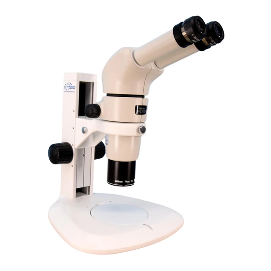
Chapter 1 Components SMZ800N Zooming Body Systems P-B Binocular Tube Diopter adjustment ring C-PSN Plain Stand Eyepiece (support pillar) Zoom knob Illuminator attachment screw hole Illuminator attachment hole SMZ800N Zooming Body Zooming body fixing screw Focus knob C-PSN Plain Stand (arm) -
Page 17: Smz1270 Zooming Body Systems
Chapter 1 Components SMZ1270 Zooming Body Systems Zoom knob P-B Binocular Tube C-FMCN Focus Mount Diopter adjustment ring Eyepiece P-PS32 Plain Stand (support pillar) Illuminator attachment hole SMZ1270 Zooming Body Focus mount fixing knob Zooming body fixing screw Fine focus knob Objective Coarse focus knob Stage plate... - Page 18 Chapter 1 Components ☆☆☆...
-
Page 19: Microscopy Procedures
Chapter Microscopy Procedures This chapter describes the basic microscopy procedures for using the SMZ800N Zooming Body system introduced in Chapter 1, “Components.” For details on the procedure for using the system combined with other devices, see Chapter 3, “Specific Operations” and Chapter 4 “Functions and Operations of the Devices.”... - Page 20 Chapter 2 Microscopy Procedures Set a sample. Place a sample on the stage plate immediately under the objective. Sample Setting a sample Adjust the diopter. Adjust the diopter to match your eyesight. For details, see Chapter 3, “5 Adjusting the Diopter.” This adjustment is required for each observer.
- Page 21 (See Chapter 3, “7 Focusing on the Sample.”) Focusing on the sample Change the magnification using the zoom knobs. Turn the zoom knobs on the right and left of the SMZ800N Zooming Body to change the magnification. The figure shows the knob turning direction and the corresponding Magnification changes in magnification.
- Page 22 Chapter 2 Microscopy Procedures ☆☆☆...
-
Page 23: Specific Operations
Chapter Specific Operations This chapter describes how to use the microscope system to observe samples. For details about using the individual devices, see Chapter 4. -
Page 24: Turning On The Power
Chapter 3 Specific Operations Turning On the Power This section lists the devices of the microscope system that require a power supply. Connect the device to the relevant power source before turning on the power. For details on the power supply required by each device, see Chapter 4, “Functions and Operations of the Devices”... -
Page 25: Adjusting The Brightness
Chapter 3 Specific Operations Adjusting the Brightness The illumination brightness can be adjusted on the following devices. Turn the brightness control dial to adjust the brightness to a comfortable level. Depending on the system configuration, some devices support remote control of the brightness. For details, see Chapter 4, “Functions and Operations of the Devices.”... -
Page 26: Switching The Optical Path Of The Tube
Chapter 3 Specific Operations Switching the Optical Path of the Tube The trinocular tubes in this microscope system are equipped with an optical path switching lever. To observe a sample using the eyepiece, switch the optical path to the binocular part. To capture images using a DS camera head, switch the optical path to the vertical tube. -
Page 27: Adjusting The Diopter
Turn the zoom knob to minimize the magnification, and then turn the diopter adjustment rings of the right and left eyepieces to bring them into focus separately. [Zoom magnification] SMZ800N Zooming Body: 1x to 8x Magnification decreases SMZ1270/SMZ1270i Zooming Body: 0.63x to 8x... -
Page 28: Focusing On The Sample
Chapter 3 Specific Operations Focusing on the Sample Focus on the sample by turning the focus knobs on the focus Upward movement mount or stand to move the zooming body (objective) up or down. The coarse knob and fine knob are on the same axis on the C-FMCN Focus Mount. - Page 29 Chapter 3 Specific Operations Torque of the focus knobs The torque of the focus knobs can be adjusted. How the torque is adjusted differs depending on the device. Adjust the torque to an appropriate level with the corresponding procedure. Notes on the torque adjustment When the torque is too low, the zooming body may slide down due to the various loads it carries, such as its own weight or the load of the counterbalance spring inside the focus unit.
-
Page 30: Changing The Magnification
The figure shows the knob turning direction and the Magnification corresponding changes in magnification. increases Turning the knob backward: Magnification increase Turning the knob forward: Magnification decrease Magnification and zoom ratio SMZ800N: 1x to 8x, 8:1 SMZ1270/SMZ1270i: 0.63x to 8x, 12.7:1 Magnification decreases Zooming in/out... -
Page 31: Switching Objectives (Using A Nosepiece)
Chapter 3 Specific Operations Switching Objectives (Using a Nosepiece) Turn the nosepiece to switch objectives. Check that the nosepiece stops at a click position when turned. There are two types of nosepieces: a standard type and a type with the status detection function. -
Page 32: Shifting A Sample
Chapter 3 Specific Operations Shifting a Sample To view another part of a sample during microscopy, use the following procedure to shift the sample. Sliding the Stage Plate Loosen the stage plate fixing screw of the P-PS32 Plain Stand, the P-DSL32 LED Diascopic Illumination Stand or the P-DSF32 Fiber Diascopic Illumination Stand to slide the stage plate. -
Page 33: Using Episcopic Illumination
Chapter 3 Specific Operations Using Episcopic Illumination The microscope system enables episcopic illumination when used with the devices listed below. All of these devices use LEDs as the light source and provide uniform illumination. Illumination emitted from the light source is passed through the objective or directly onto the sample by the fiber and the image created by the light reflected by the sample is observed. -
Page 34: Using Epi-Fluorescence Illumination
Chapter 3 Specific Operations Using Epi-Fluorescence Illumination Epi-fluorescence microscopy used for observing fluorescence images requires an optical element such as a fluorescence filter and a bright light source such as mercury lamp. With a filter cube attached to the turret inside the device, the filter cube is brought into the optical path by the rotation of the turret, resulting in the generation of epi-fluorescence illumination. -
Page 35: Selecting A Filter Cube
Locating a target in the sample For epi-fluorescence microscopy, Nikon recommends locating a target using bright-field diascopic illumination (OCC illumination) and then switching to epi-fluorescence, rather than emitting strong excitation light to the sample from the beginning. -
Page 36: Using Diascopic Illumination
Chapter 3 Specific Operations Using Diascopic Illumination The microscope system enables diascopic illumination when used with the diascopic illumination stand. Diascopic illumination stands that use LEDs as the light source provide bright and uniform illumination. Observe an image visible by diascopic illumination that passes through the sample and enters the objective. -
Page 37: Capturing Images
When using diascopic illumination, first capture an image of the top surface of the stage plate. When using episcopic illumination, first capture an image of any white subject. Then, press the WB button to execute white balance adjustment. (For fluorescent photomicrography, Nikon recommends adjusting the white balance under normal bright-field microscopy conditions before capturing images.) Adjust the position of the sample. -
Page 38: Tips On Microscope Settings For Photomicroscopy
Chapter 3 Specific Operations Tips on Microscope Settings for Photomicroscopy 13.2 Confirming the photomicrographic range The image on the monitor represents the photomicrographic range. Adjusting to eliminate extraneous light Cover the eyepiece with a piece of cloth or similar item. ... -
Page 39: Functions And Operations Of The Devices
Chapter Functions and Operations of the Devices This chapter describes the main functions and procedure for using the devices. -
Page 40: Zooming Bodies
Zooming Bodies There are two types of zoom bodies: the SMZ800N Zooming Body with a zoom magnification of 1x to 8x and the SMZ1270/SMZ1270i Zooming Body with a zoom magnification of 0.63x to 8x. The SMZ1270i zooming body is equipped with a magnification detection function. -
Page 41: Smz1270 Zooming Body, Smz1270I Zooming Body
Chapter 4 Functions and Operations of the Devices SMZ1270 Zooming Body, SMZ1270i Zooming Body Zooming body The SMZ1270 Zooming Body is for parallel-optics stereo microscopes. Attach it to various types of focus mounts or stands with focus knobs. Attach an objective to the objective mount. Up to two objectives Zoom knob can be attached if a nosepiece is attached. - Page 42 Chapter 4 Functions and Operations of the Devices Activating and deactivating zoom click stops Zoom knob Insert the hex wrench (nominal designation: 2) supplied with click stops: the zooming body into the hole on the rear side of the right zoom knob.
-
Page 43: Focus Mounts
Chapter 4 Functions and Operations of the Devices Focus Mounts A focus mount with a zooming body attached is used for focusing on a specimen by turning its focus knob. There are three kinds of focus mounts: C-FMAN, C-FMBN and C-FMCN focus mounts. C-FMAN Focus Mount Zooming body mount The C-FMAN Focus Mount attaches to a US-3 Universal Stand... -
Page 44: C-Fmbn Focus Mount
Chapter 4 Functions and Operations of the Devices C-FMBN Focus Mount Zooming body mount The C-FMBN Focus Mount attaches to a G-US1A Universal Table Clamp Stand or a G-US2 Universal Table Stand. Focus knob Turn the right and left focus knobs to move the zooming body vertically and to focus on samples. -
Page 45: C-Fmcn Focus Mount
Chapter 4 Functions and Operations of the Devices C-FMCN Focus Mount Zooming body mount The C-FMCN Focus Mount attaches to the following three types Torque adjustment ring (base of of stands with a support pillar of 32 mm dia. the coarse focus knob on the left) ... - Page 46 Chapter 4 Functions and Operations of the Devices Anti-drop collar An anti-drop collar is supplied with the focus mount. When using a focus mount attached in the middle of the support pillar, be sure to attach the anti-drop collar under the focus mount so that it fits.
-
Page 47: Nosepieces
C-LEDS Hybrid LED Stand. P-RN2 Nosepiece Attach the P-RN2 Nosepiece to the objective mount of the SMZ800N Zooming Body or the SMZ1270 Zooming Body. Two objectives attached to the nosepiece can be switched by turning the nosepiece. Vertical observation with a single-side optical path is also possible. -
Page 48: P-Rni2 Intelligent Nosepiece
Chapter 4 Functions and Operations of the Devices P-RNI2 Intelligent Nosepiece This nosepiece has a function for detecting the address of an objective. Attach it to the objective mount on the SMZ1270i Nosepiece Zooming Body. cable The two objectives attached to the nosepiece can be switched by turning the nosepiece. -
Page 49: Objectives
Chapter 4 Functions and Operations of the Devices Objectives The microscope system supports the objectives in the following table. Attach objectives to the zooming body or nosepiece. Model Magnification NA (max.) Working distance Objective mount P-Achro 0.5X * 0.5x 0.053 189 mm M58 x 1.25 P-ED Plan 0.75X... -
Page 50: Stands (With Focus Knobs)
Chapter 4 Functions and Operations of the Devices Stands (with Focus Knobs) The stand is composed of a base, support pillar and arm. To focus on the sample, vertically move the zooming body attached to the arm using a focus knob on the support pillar. C-PSN/C-PSCN Plain Stand Tool holder (rear) The C-PSN and C-PSCN are plain stands with specifications... -
Page 51: C-Ds Dia Illumination Stand
Chapter 4 Functions and Operations of the Devices Attachable optional devices Stage clip (sample holder) C-LSL2 LED Epi Illuminator 2 (attached directly or via a G-EIA Flexible Arm or an SMZ-U Epi Arm) C-FID2 Double Arm Fiber Illuminator ... -
Page 52: Universal Stands
Chapter 4 Functions and Operations of the Devices Universal Stands These stands are equipped with an arm that can be moved horizontally and vertically. Attach a focus mount to the arm when using a stand. G-US1A Universal Table Clamp Stand Clamp this stand to a table, etc. -
Page 53: Stands (Exclusive Model)
Chapter 4 Functions and Operations of the Devices Stands (Exclusive Model) The series of stands exclusive to this microscope system. Attach a C-FMCN Focus Mount to the support pillar of the stand. The stand's base with a large glass plate enhances usability and enables easier observation of samples in a container such as a petri dish. -
Page 54: P-Dsl32 Led Diascopic Illumination Stand
Chapter 4 Functions and Operations of the Devices Screw holes for attaching optional devices 20 100 The base’s top board has screw holes for attaching various devices. Screw holes (2) to (4) do not go right the way 4-M5 through to prevent liquid penetrating into the base. Depth 7 2-M4: Positioned under the stage plate attachment... -
Page 55: Stages
Chapter 4 Functions and Operations of the Devices Stages P-SXY64 XY Stage This stage shifts the glass plate in the X and Y directions when Glass plate Stage X the X/Y shift knobs are turned. Attach this stage instead of the shift knob base. -
Page 56: Circular Floating Stage 2
Chapter 4 Functions and Operations of the Devices Circular Floating Stage 2 This stage is movable in the range of ±20 mm in the radial direction. The height of the stage is 17.7 mm. Circular Floating Stage 2 Attach the stage to the position where the stage plate was removed from the base. -
Page 57: Tubes
Chapter 4 Functions and Operations of the Devices Tubes This microscope system can be used with the following tubes. P-B Binocular Tube This tube is the standard type for this microscope system. Attach two eyepieces of the same magnification (10x, 15x, 20x or 30x) to the binocular eyepiece sleeve in order to observe erected images. -
Page 58: Trinocular Tubes
Chapter 4 Functions and Operations of the Devices Trinocular Tubes There are three types of trinocular tubes as follows: P-TERG100 Trinocular Tilting Tube P-TERG50 Trinocular Tilting Tube P-T100 Trinocular tube Attach two eyepieces of the same magnification (10x, 15x, 20x or 30x) to the binocular sleeves of the trinocular tube in order to observe Optical path switching lever... -
Page 59: Episcopic Illuminators
See the following table for the types of objectives usable with the coaxial epi illuminator and the recommended zoom magnifications. Usable objectives and recommended zoom magnifications Zoom magnification Objective SMZ800N Zooming Body SMZ1270/1270i Zooming Body 0.5X 3x - 4x - 0.75X... -
Page 60: C-Fdf Flexible Double Arm Fiber Illumination Unit
Chapter 4 Functions and Operations of the Devices C-FDF Flexible Double Arm Fiber Illumination Unit 10.2 The C-FDF for illuminating samples is a fiber connected to the C-FLED2 LED Light Source for Fiber Illuminator. To C-FLED2 LED Light Source for Two fibers are held by the C-FIDH Fiber Holder. -
Page 61: C-Fir Ring Fiber Illumination Unit
Chapter 4 Functions and Operations of the Devices C-FIR Ring Fiber Illumination Unit 10.4 The C-FIR is a ring shaped fiber illuminator that attaches to the external tip of the objective and connects to the C-FLED2 LED Light Source for Fiber Illuminator. The edge face of the sample can be illuminated evenly using this To C-FLED2 ring-shaped fiber. -
Page 62: Epi-Fluorescence Attachment
Chapter 4 Functions and Operations of the Devices Epi-Fluorescence Attachment This microscope system can be used with the P-EFL Epi Fluorescence Attachment to perform epi-fluorescence microscopy P-EFL Epi Fluorescence Attachment 11.1 Filter cube indication This epi-fluorescence attachment is used with filter label cubes attached to the turret inside the attachment. - Page 63 The periphery of the image may become dark when an intermediate tube such as a beam splitter is used together. OCC light shielding plate When using an epi-fluorescence attachment in combination with a P-DSL32 LED Diascopic Illumination Stand, Nikon recommends closing the OCC light shielding plate on the dia-illumination completely. This can decrease background noise caused by intrinsic fluorescence in the diascopic illuminator.
-
Page 64: Diascopic Illuminators
Chapter 4 Functions and Operations of the Devices Diascopic Illuminators The primary diascopic illuminator for this microscope system consists of a stand equipped with an illuminating optical system. A dark-field illuminator and polarizing illuminator are also available. P-DSL32 LED Diascopic Illumination Stand 12.1 The P-DSL32 is a stand equipped with diascopic illumination optical systems and the focus mechanism of the support pillar vertical movement type. - Page 65 Chapter 4 Functions and Operations of the Devices LED brightness control selection switch On: Assigns control to the control box. LED brightness control selection switch Off: Assigns control to the base. For details about the P2-CTLB Control Box, see “13 P2-CTLB Control Box.” ...
-
Page 66: P-Dsf32 Fiber Diascopic Illumination Stand
Chapter 4 Functions and Operations of the Devices Screw holes for attaching optional devices 20 100 The base’s top board has screw holes for attaching various 4-M5 devices. Screw holes (2) to (4) do not go right the way Depth 7 through to prevent liquid penetrating into the base. - Page 67 Chapter 4 Functions and Operations of the Devices OCC (oblique coherent contrast) illumination This stand supports OCC illumination so that a transparent sample can be observed at high contrast using diascopic illumination with a white LED. OCC illumination is an oblique illumination method suitable for observing the phase objects, where a sample is obliquely illuminated with a coherent illuminating light by shielding a part of the optical path using a shading plate.
- Page 68 Chapter 4 Functions and Operations of the Devices Screw holes for attaching optional devices 20 100 The base’s top board has screw holes for attaching various 4-M5 devices. Screw holes (2) to (4) do not go right the way Depth 7 through to prevent liquid penetrating into the base.
-
Page 69: P-Df2 Led Dark Field Unit 2
Chapter 4 Functions and Operations of the Devices P-DF2 LED Dark Field Unit 2 12.3 This dark-field illumination unit has LEDs that are tilted and positioned like a ring. The unit is attached to the base of the stand. For details, refer to the instruction manual for the P-DF2 LED Dark Field Unit 2. C-POL Simple Polarizing Attachment 12.4 The C-POL is a simple polarizing device that consists of the... -
Page 70: P2-Ctlb Control Box
Chapter 4 Functions and Operations of the Devices P2-CTLB Control Box The P2-CTLB Control Box supplies illumination power to the P-DSL32 LED Diascopic Illumination Stand, turns on or off the LED power source, adjusts brightness and monitors the light intensity. Connect a PC (software: NIS-Elements) to the control box in order to control illumination. -
Page 71: Other Devices
Chapter 4 Functions and Operations of the Devices Other Devices In addition to the devices described in the earlier sections, the following optional devices can be used with this microscope system: SMZ10A Aperture Unit 14.1 To increase the depth of focus during image capture, attach this unit between the zooming body and the tube. -
Page 72: P-Ier Eyelevel Riser
Chapter 4 Functions and Operations of the Devices P-IER Eyelevel Riser 14.3 Attach the P-IER between the zooming body and the tube to raise the eyelevel 25 mm. Up to two eyelevel risers can be used by putting one on top of the P-IER Eyelevel Riser other. -
Page 73: Assembly
Be very careful not to let fingers be caught when putting it down. Tools necessary for assembly Tools Devices that supply tools Hex wrench (nominal designation: 2) SMZ800N, SMZ1270, SMZ1270i Zooming Body Hex wrench (nominal designation: 2.5) P-SXY64 XY Stage Hex wrench (nominal designation: 3) P-SXY64 XY Stage... -
Page 74: System Configuration
C-LEDS USB cable Plain Stand Dia Illumination Stand* Hybrid LED Stand* To the DS-L3*/DS-L4* camera control unit or a C-DSLU2 LED Unit for SMZ800N SMZ1270 SMZ1270i Power cable PC (NIS-Elements)* Dia Illumination Stand 2* Zooming Body Zooming Body Zooming Body... - Page 75 Chapter 5 Assembly C-LSL2 LED Epi Illuminator 2* SMZ-U Epi Arm G-EIA Flexible Arm C-FDF Flexible Double Arm Fiber Illumination Unit C-FLED2 LED Light source for fiber illuminator* C-FLED2 is attached to a stand with a base plate. C-FIDH Fiber Holder C-FID2 Double Arm Fiber Illuminator Objective (P-ED Plan 2X/WF...
-
Page 76: Device List
Device List Select one device from each group marked with “” and configure the basic microscopy system. Basic System Device Name Model Remarks Configuration Zooming Body SMZ800N Main Body Zooming Body SMZ1270 Zooming Body SMZ1270i Focus Mount C-FMAN ... - Page 77 Chapter 5 Assembly Basic System Device Name Model Remarks Configuration Epi Fluorescence Attachment P-EFL Unusable with the C-PSN/C-PSCN or C-LEDS Optional With three empty cubes and a shielding plate Epi Fluorescence P-EFL GFP-B Optional Attachment P-EFL GFP-L Optional Filter Cube P-EFLC Optional P-EFLBF...
-
Page 78: Assembly Procedures
Chapter 5 Assembly Assembly Procedures The stereo microscopes SMZ800N/SMZ1270/SMZ1270i Zooming Bodies are the system microscopes that can be used in various device configurations. This chapter describes the basic device assembly procedures. See figures in Chapter 1, “Components” for basic configuration examples. This chapter also describes the assembly procedures for various optional devices such as illuminators that can be added to the basic configuration. - Page 79 Chapter 5 Assembly [P-PS32 Plain Stand, P-DSL32 LED Diascopic Illumination Stand, P-DSF32 Fiber Diascopic Illumination Stand] Attach the stage plate supplied with the stand to the base. The procedure for attaching the stage plate is the same for all stand types. First loosen the M4 set screw for the stage plate located at the middle front of the stand’s base using a hex driver (nominal designation: 2).
- Page 80 Chapter 5 Assembly Beware of overhang of cables When these cables are connected, the connectors (cables) overhang to the left of the base. Be careful so that they do not interfere with other devices such as a control box or they are not accidentally touched and disconnected while attaching devices or performing observation.
- Page 81 Chapter 5 Assembly Attach a focus mount. C-FMCN Focus Mount attachment The C-FMCN Focus Mount can be attached to the following stands: P-PS32 Plain Stand P-DSL32 LED Diascopic Illumination Stand P-DSF32 Fiber Diascopic Illumination Stand [Focus mount orientation] Attach the focus mount to the stand so that the focus mount faces the front of the stand as shown in the figure.
- Page 82 Chapter 5 Assembly CAUTION Use of the anti-drop collar When using a C-FMCN Focus Mount attached in the middle of the support pillar, be sure to use the anti-drop collar. Otherwise the zooming body may slide down when the focus mount fixing screw is loosened. This may result in injury such as pinching fingers between the objective and sample, or damage to the sample on the stage plate by the objective.
- Page 83 Chapter 5 Assembly Attach a tube. Note on device combinations A P-TERG100 or P-TERG50 trinocular tube cannot be used in the microscope system that includes any of the following stands: C−PSN/C-PSCN Plain Stand C-DS Dia Illumination Stand C-LEDS Hybrid LED Stand Attach a tube to the zooming body.
- Page 84 Chapter 5 Assembly Attach an objective. Attach the objective to be used to the zooming body. The procedure for attaching an objective is the same for all types. Screw the objective into the objective attachment screw hole at the lower plane of the zooming body. Insert it straight from the bottom and securely screw it until it touches the abutting joint.
-
Page 85: Assembly Of Other Devices (Optional)
Attach a nosepiece before performing 3.1, step 6 “Install an objective.” The P-RN2 Nosepiece is intended for the SMZ800N Zooming Body or the SMZ1270 Zooming Body, and the P-RNI2 Intelligent Nosepiece is intended for the SMZ1270i Zooming Body. The procedure for attaching a nosepiece is the same for both types. - Page 86 Chapter 5 Assembly Attachment tool Be sure to insert the attachment tool straight along the two grooves of the nosepiece. Check the groove positions Groove Groove by referring to the figure “Nosepiece viewed from the bottom.” If the tool is inserted at an angle, the convex part of the tool contacts the objective, resulting in scratches or damage to the objective.
- Page 87 Chapter 5 Assembly Attach a P-EFL Epi Fluorescence Attachment. Note on device combinations The P-EFL Epi Fluorescence Attachment cannot be used in the microscope system that includes any of the following stands: C−PSN/C-PSCN Plain Stand C-DS Dia Illumination Stand ...
- Page 88 Chapter 5 Assembly Align the dovetail groove of the filter cube with the internal dovetail and insert the filter cube until it reaches the limit. The installation positions are numbered from [1] to [4] and are shown on the left inside of the filter cube attachment hole.
- Page 89 Chapter 5 Assembly Align two screw holes on the upper plane of the nosepiece with the screw holes on the shielding plate, and securely attach the shielding plate using the two M2.5 hexagon socket head bolts used for attaching the ring. Securely attaching the shielding plate ...
- Page 90 Chapter 5 Assembly Bond along the Fill in the gap between the bottom part and the circumference. barrier filter with adhesive. Barrier filter bonding - 1 Bond to attach the barrier filter to the top part. Push the barrier filter into the position shown in the figure of the top part until it hits the bonding surface.
- Page 91 Chapter 5 Assembly Assembling each part of the P-EFLC. Securely attach the cover to the bottom part by tightening the four screws on the sides. Securely attach the top part by tightening the two screws on the top. Cover attached Top part attached (complete) P-EFLC assembly...
- Page 92 When using a P-PS32 Plain Stand, use a 90-dia. stage plate separately. Circular Floating Stage 2 attachment The Circular Floating Stage 2 can be attached by fitting it into the base of the C-PSN/C-PSCN. Nikon recommends securely attaching the stage by tightening bolts.
- Page 93 Chapter 5 Assembly Attach a C-POL Simple Polarizing Attachment. Attach a simple polarizing attachment to a P-DSL32, a P-DSF32 or a C-DS stand. This simple polarizing attachment cannot be used with a P-ED Plan 2X/WF. Fixing screw Loosen the M4 set screw for the stage plate of the base using a hex driver (nominal designation: 2) to remove the stage plate, and alternatively place the base plate of the polarizer so that it fits the base.
- Page 94 Chapter 5 Assembly Attach the glass plate supplied with the P-SXY64 XY Stage so that it fits the upper plate of the stage. The glass plate has chamfered corners including one small chamfered corner. Align the small chamfered corner with the right rear side of the stage (as viewed from the front) to fit the glass plate on the stage, and tighten the glass plate fixing screw.
- Page 95 Chapter 5 Assembly Attach a P-IER Eyelevel Riser Notes on combination Do not use more than two eyelevel risers at once or together with other intermediate tubes such as a beam splitter or a coaxial episcopic illuminator. Doing so will cause vignetting around the image. Attach the P-IER Eyelevel Riser after performing 3.1, step 3 “Attach a zooming body.”...
- Page 96 Chapter 5 Assembly ☆☆☆...
-
Page 97: Troubleshooting
If problems that are not listed in the table are detected or the problem still persists even after the indicated measures are taken, turn off the device and contact your nearest Nikon representative. -
Page 98: Image Viewing
Chapter 6 Troubleshooting Image Viewing Problem Cause Measure Devices are not attached correctly. Attach the devices correctly. The optical path switching lever of the tube is Position the lever correctly. positioned partway. Part of the field of view is Firmly turn the nosepiece to the click position for missing. -
Page 99: Maintenance And Storage
Chapter Maintenance and Storage This chapter describes how to maintain and store the product. -
Page 100: Cleaning
Chapter 7 Maintenance and Storage Cleaning Clean and disinfect the microscope and lenses as described in the procedures below. Tools used for cleaning Blower Soft brush Soft cotton cloth, lens tissue, gauze, etc. Absolute alcohol (ethyl or methyl alcohol), medical alcohol CAUTION ... -
Page 101: Disinfecting The Product
Switch off the device (press the switch to the “O” position). If the device is warm, wait for it to cool before covering it with a cover. Periodic Inspection (Charged) To maintain the performance of this product, Nikon recommends periodic inspection (chargeable service). Contact your nearest Nikon representative for details. - Page 102 Chapter 7 Maintenance and Storage ☆☆☆...
-
Page 103: Specifications
Chapter Specifications... -
Page 104: Microscopy (Principles)
It is intended for the researchers, medical professional and those who work on experiments in the field of pathology and cytology. Performance Properties Stereo microscope Name Zooming body Zooming body Model SMZ800N SMZ1270/1270i Zoom ratio 12.7:1 Magnification 1x to 8x 0.63x to 8x Distance... - Page 105 Chapter 8 Specifications Focus mount Name Focus Mount Focus Mount Focus Mount Model C-FMAN C-FMBN C-FMCN Vertical Through rotation of the right/left Through rotation of the right/left Through rotation of the right/left movement single-axis focus knob single-axis focus knob single-axis coarse/fine knob method Knob torque adjustable...
- Page 106 Chapter 8 Specifications Name Plain Stand LED Diascopic Illumination Stand Fiber Diascopic Illumination Stand Model P-PS32 P-DSL32 P-DSF32 Stage plate Black surface and milky white Transparent glass plate, 180 mm Transparent glass plate, 180 mm surface, acrylic plate, 180 mm dia. dia.
- Page 107 Chapter 8 Specifications Tube Name Binocular Tube Trinocular Tilting Tube Trinocular Tube Model P-TERG100 P-T100 P-TERG50 Angle of 20° 0 to 30° 10° depression (continuously changeable) Binocular/tube None Lever push-in/pull-out Lever push-in/pull-out optical-path switching Eye point Height: Approx. 121 mm from the Variation: Approx.
- Page 108 Chapter 8 Specifications Objective Name Objective Objective Objective Objective Model P-Achro 0.5X P-ED Plan 0.75X P-Plan 1X P-ED Plan 1.5X/WF Magnification 0.5x 0.75x 1.5x Numerical 0.053 0.079 0.105 0.158 aperture (max.) Working 189 mm 117 mm 78 mm 44 mm distance Objective mount M58 x 1.25...
- Page 109 Chapter 8 Specifications Epi fluorescence attachment Name Epi Fluorescence Attachment Model P-EFL Magnification Attachment of filter cubes to the internal turret Epi-fl illumination Up to four filter cubes can be attached. Turret switching: Knob rotation method ...
-
Page 110: Physical Properties
Dimensions and mass vary depending on the composition described in Chapter 1, “Components.” (W x H x L) and SMZ800N Zooming Body system: 292 mm x 376 mm x 387 mm, approx. 5.5 kg mass (reference) SMZ1270 Zooming Body system: 300 mm x 402 mm x 420 mm, approx. 6.5 kg ...