
Related Manuals for Nikon SMZ25


Summary of Contents for Nikon SMZ25
- Page 1 M608EN11(1/2) 23.1.31.NW_EN *M608EN11* Research Stereo Microscope SMZ25/SMZ18 Instruction Manual...
-
Page 3: Introduction
Zooming Body. To ensure correct usage, read this manual carefully before operating this product. ● No part of this manual may be reproduced or transmitted in any form without prior written permission from Nikon. ● The contents of this manual are subject to change without notice. -
Page 4: Table Of Contents
Contents Contents Introduction ......................... i Safety Precautions ......................v Label Attached to the Product ..................v WARNING and CAUTION Symbols ................vii WARNING ......................... viii CAUTION ........................x Notes on Handling the Product ..................xii Components ..................... 1 Microscopy System Using Episcopic Illumination ............ 2 Names of the Devices and Operation Sections .......... - Page 5 Internally Saved Information ................... 85 Functions and Operations of the Devices ........... 87 Zooming Bodies ..................... 88 SMZ18 Zooming Body ..................88 SMZ25 Zooming Body ..................89 Focus Units, Focus Mount ..................92 P2-FU Focus Unit ..................... 92 P2-MFU Motorized Focus Unit ................. 93 P2-FMDN Focus Mount ..................
- Page 6 Contents Bases, Stands, and Stages .................. 100 P2-PB Plain Base ................... 100 P2-DBL LED Diascopic Illumination Base ............101 P2-DBF Fiber Diascopic Illumination Base ............ 101 P-PS32 Plain Stand ..................102 P-DSL32 LED Diascopic Illumination Stand ........... 103 P-DSF32 Fiber Diascopic Illumination Stand ..........103 P-SXY64 XY Stage ..................
-
Page 7: Safety Precautions
Safety Precautions Safety Precautions • To ensure correct usage, read this instruction manual carefully before using the equipment. Read also the instruction manuals if separately supplied with the components of the equipment. • Be sure to follow the “Safety Precautions” written at the beginning of the instruction manual. •... - Page 8 Safety Precautions Heat caution label Caution: Heat of the empty cube Immediately after diascopic observation using an epi-fluorescence attachment, the front face of the empty cube may become hot, resulting in burns. Do not touch the front face of the empty cube.
-
Page 9: Warning And Caution Symbols
Safety Precautions Biohazard label Caution: Biohazard This symbol calls your attention to the following: • The product may become biohazardous if a sample contacts the product. • To avoid exposure to biohazard, do not touch contaminated parts with your bare hands. •... - Page 10 (which may take observed. approximately 30 minutes) before replacing the Safety is a top design priority for Nikon products. lamp. Safety is ensured as long as the user observes all ● Do not place fabric, paper, or highly flammable of the warnings and cautions given in the manuals, volatile materials (i.e.
- Page 11 Safety Precautions WARNING Hazards of mercury lamps Hazardous sample handling (when using the epi-fluorescence attachment) This product can also be used for microscopy and The light source used with the epi-fluorescence imaging of biological samples (cells/tissues) in a attachment (HG Precentered Fiber Illuminator) petri dish.
- Page 12 If water or a chemical solution enters this RISK GROUP 2 IEC62471: 2006” product, stop using the product, and contact your nearest Nikon representative. Also pay attention to brightness control of the light source and to avoid looking at bright light for an Remove any covers from the product before extended period.
- Page 13 Safety Precautions CAUTION ● The total mass of the microscope system is over 20 kg. When moving the system to another location, temporarily separate the removable devices and carry the system while firmly holding the hand holding portions of the base, with multiple persons.
-
Page 14: Notes On Handling The Product
Electromagnetic environment mold and/or condensation may be generated on the lenses. Furthermore, performance Nikon recommends evaluating the electromagnetic deterioration and malfunction may occur. environment of the installation site before using this product. -
Page 15: Components
Chapter Components This stereo microscope system can be composed of the SMZ25 Zooming Body or SMZ18 Zooming Body attached to the motorized or manual focus mount and devices such as bases, objectives, tubes and episcopic illuminators that can be arbitrarily selected. -
Page 16: Microscopy System Using Episcopic Illumination
Chapter 1 Components Microscopy System Using Episcopic Illumination Names of the Devices and Operation Sections DS camera P2-TERG 100 Optical path switching lever Trinocular Tilting Tube P2-FU Focus Unit P2-RLY Relay Box P2-CIA Coaxial Epi Illuminator (To P2-CTLB Control Box) Zoom knob P2-RNI2 Intelligent Nosepiece... -
Page 17: Microscopy System Using Diascopic Illumination And Epi-Fluorescence Illumination
Turret address check window P2-RNI2 Intelligent Nosepiece P2-EFLM Motorized Epi Fluorescence P2-RC Remote Controller Attachment (See “2.2 Buttons on the P2-RC Remote Controller.”) SMZ25 Zooming Body P2-CTLA Control Box C-HGFIE HG precentered fiber Light shielding plate illuminator (Refer to the instruction manual... -
Page 18: Buttons On The P2-Rc Remote Controller
Chapter 1 Components Buttons on the P2-RC Remote Controller (9) Capture button (1) LCD (2) Backlight control dial (6) Filter cube switching buttons (4) Fine/coarse focus switching button (4) Fine/coarse focus switching button (8) Z-reset button (3) Focus knob FL Cube FL Cube (3) Focus knob (7) LCD display switching... -
Page 19: Compact System
Chapter 1 Components Compact System Names of the Devices and Operation Sections DS camera P2-TL100 Trinocular Tube L Optical path switching lever Zoom knob P2-FMDN Focus Mount SMZ18 Zooming Body Coarse focus knob Fine focus knob Objective P-PS32 Plain Stand Clamp tool Diopter adjustment ring Zoom knob... - Page 20 Chapter 1 Components ☆☆☆...
-
Page 21: Microscopy Procedures
Chapter Microscopy Procedures This chapter describes the microscopy procedures listed below. The devices used in the descriptions are based on the configuration examples given in the previous chapter. Procedure 1: Procedure for microscopy under episcopic illumination Procedure 2: Procedure for microscopy under diascopic illumination Procedure 3: Procedure for epi-fluorescence microscopy It is assumed that all required components are attached to the microscope with all necessary cables properly connected. -
Page 22: Operation Flowchart
Chapter 2 Microscopy Procedures Operation Flowchart Microscopy under episcopic illumination or diascopic illumination Turn on the power. Set a sample. Bring an objective into the optical path. Turn on the illumination and adjust the brightness. Set the optical path to 100% to the binocular part. -
Page 23: Procedure For Microscopy Under Episcopic Illumination
Chapter 2 Microscopy Procedures Procedure for Microscopy under Episcopic Illumination This section describes the procedure for performing microscopy under episcopic illumination using the SMZ18 Zooming Body combined with the P2-CIA Coaxial Epi Illuminator. Turn on the power. Turn on the P2-CTLB Control Box by pressing the power switch to the “|”... - Page 24 Chapter 2 Microscopy Procedures Turn on illumination and adjust the brightness. Refer to the instruction manual for the C-FLED2 LED Light Source for Fiber Illuminator. Aperture diaphragm The SMZ18 Zooming Body is equipped with an aperture diaphragm. Turn the aperture diaphragm dial counterclockwise (Ο...
- Page 25 Chapter 2 Microscopy Procedures Adjust the interpupillary. Adjust to match the distance between your right and left eyes. Look into both eyepieces and move the binocular part of the tube so that the right and left fields of view merge into a single circle. This adjustment is required for each user.
- Page 26 Chapter 2 Microscopy Procedures Change the magnification using the zoom knobs. Turn the zoom knobs on the right and left of the SMZ18 Zooming Body to change the magnification. The figure shows the turning directions of a knob and the corresponding changes in magnification.
-
Page 27: Procedure For Microscopy Under Diascopic Illumination
Microscopy Procedures Procedure for Microscopy under Diascopic Illumination This section describes the procedure for microscopy under diascopic illumination using the SMZ25 Zooming Body combined with the P2-DBL LED Diascopic Illumination Base. For the same operations as in “2 Procedure for Microscopy under Episcopic Illumination,” details are omitted. - Page 28 Chapter 8, “8.1 P2-DBL LED Diascopic Illumination Base.” Aperture diaphragm The SMZ25 Zooming Body is equipped with an aperture diaphragm. Turn the aperture diaphragm dial counterclockwise (O side) to fully open the aperture. (For details about using the aperture diaphragm, see Chapter 7, “10 Using the Aperture...
- Page 29 Chapter 2 Microscopy Procedures Adjust the interpupillary. → Step 8 in “2 Procedure for Microscopy Under Episcopic Illumination” Adjust the focus. Turn the focus knobs of the remote controller to move the focus mount of the focus unit vertically and focus on the Fine/coarse focus sample.
- Page 30 0.1x. When a step size is selected, the Zooming in/out corresponding step LED indicator lights. (See Chapter 8, “1.2 SMZ25 Zooming Body.”) Turn off the power after completing microscopy. Turn off the P2-CTLA Control Box by pressing the power switch to the “O”...
-
Page 31: Procedure For Epi-Fluorescence Microscopy
Chapter 2 Microscopy Procedures Procedure for Epi-fluorescence Microscopy After locating a target in a sample in “3 Procedure for Microscopy Under Diascopic Illumination” (steps 1 to 10), follow the procedure below: Notes on epi-fluorescence microscopy • Do not use the epi-fluorescence attachment when the filter cube replacement cover is open. Harmful light including ultraviolet light may leak and affect fluorescence observation. - Page 32 Chapter 2 Microscopy Procedures Adjust the angle of the light shielding plate. Change the angle of the light shielding plate to 45° to prevent light reflected from the objective from entering your eyes. Adjusting the angle of the light shielding plate Turn on the HG precentered fiber illuminator and adjust the brightness.
-
Page 33: Assembling
Chapter Assembling This chapter contains the SMZ18/SMZ25 system configuration diagrams and lists of the system components, and explains how to assemble the systems. Before starting assembling, read the appropriate notes such as CAUTION “11 Cautions on assembling and installing the product”... -
Page 34: System Configuration
Control Box P2-FM Focus Mount Adapter P2 RLYC Relay Cable Signal cable Signal cable ZOOM** NP** Signal cable SMZ18 SMZ25 P2-RNI2 ZOOM** Zooming Body Zooming Body Intelligent Nosepiece P2-CTLA [E] [F] [H] or P2-CTLB Control Box P2-RLY Relay Box Objective... - Page 35 Chapter 3 Assembling Control Box P2-RC Remote Controller P2-CTLB P2-CTLA Control Box Control Box (Connectors: HGFIE, USB, LEDDIA, (Connectors: FOOT, REMOTE, HGFIE, RELAY, and DC24V IN) USB, LEDDIA, STAND, and DC24V IN) AZ-FSW Foot Switch 24V AC Adapter and power cable AZ-PCR Photo Release C-FDF...
-
Page 36: Device List
EPI system system/EPI Remarks system + EPI-FL system system √ √ SMZ18 Zooming Body √ √ Main Body SMZ25 Zooming Body P2-MFU Motorized Focus Unit √ √ Focus Unit or P2-FU Focus Unit Focus Mount P2-FMDN Focus Mount √ √... - Page 37 Chapter 3 Assembling Compact Compact DIA + EPI-FL system/DIA Device Model name Device name EPI system system/EPI Remarks system + EPI-FL system system P2-EFLM Motorized Epi Fluorescence With 3 empty cubes and a light Attachment shielding plate P2-EFLI Epi Fluorescence Attachment P2-EFL GFP-B Filter Cube Epi Fluorescence √...
-
Page 38: Assembly Procedures
Assembling Assembly Procedures The SMZ18 and SMZ25 stereo microscopes are system microscopes that can be used in various device configurations. This chapter describes how to assemble the following four systems. • Microscope system using episcopic illumination (referred to as the “EPI System” in this chapter) •... - Page 39 Chapter 3 Assembling Place the focus unit in the recession of the polystyrene piece as show in the figure. Positioning pins Fitting the focus unit Hold the base with the two base side positioning holes aligned with the two positioning pins on the focus unit, screw the four M8 hexagon socket head bolts (supplied with the focus mount) from the bottom of the base and tighten firmly using the hex...
- Page 40 Chapter 3 Assembling Glass stage plate handling precautions Be very careful when handling the glass stage plate. Before attaching the glass stage plate, attach all other components in order to avoid the risk of breaking the glass during assembly. Loosen the M4 set screw for the stage plate in the front center of the base using the hex driver (nominal designation: 2).
- Page 41 Chapter 3 Assembling Attach an intelligent nosepiece or focus mount adapter. Attach the intelligent nosepiece or focus mount adapter to the focus unit. The attachment procedure is the same for both the intelligent nosepiece and focus mount adapter. The following figure shows an example of attaching the intelligent nosepiece to the P2-FU Focus Unit. Remove the two rubber caps from the fixing bolt holes at the right rear of the intelligent nosepiece (as viewed from the front).
- Page 42 Signal cable Attach a zooming body. Attach the SMZ18 or SMZ25 Zooming Body to the intelligent nosepiece or focus mount adapter. The attachment procedure is the same for all zooming body types. The following figure shows an example of attaching the SMZ18 Zooming Body to the intelligent nosepiece.
- Page 43 Connecting signal cables The signal cable for the SMZ25 comes from the left side of the zooming body. In case of the SMZ18, connect the signal cable supplied with the SMZ18 to the round connector on the left side of the zooming body.
- Page 44 4N75 INSPECTION EQUIPMENT ZOOM SMZ25 MADE IN JAPAN the relay box is explained in step [5]) Bring out the cable from the SMZ zooming body along the notch on the focus unit cover and connect to the connector “ZOOM.”...
- Page 45 Chapter 3 Assembling Clamp the relay box cable using the arm clamps. Clamps Clamping a cable Place the relay box arms over the focus unit as shown in the figure, align the screw holes of the arm with the two screw holes at the back of the focus unit, and attach it by tightening the M5 hexagon socket head bolts supplied with the relay box using the hex driver (nominal designation: 4).
- Page 46 Chapter 3 Assembling Attach a coaxial epi illuminator. (for the EPI system) Attach the coaxial epi illuminator to the zooming body. Completely loosen the M4 set screw for the illuminator at the top front of the zooming body using the hex driver (nominal designation: 2). Align and fit the round dovetail at the bottom of the coaxial epi illuminator with the round dovetail of the zooming body and tighten the fixing screw.
- Page 47 Chapter 3 Assembling Attach an epi fluorescence attachment. (for the DIA + EPI-FL system) Attach the P2-EFLM Motorized Epi Fluorescence Attachment or the P2-EFLI Epi Fluorescence Attachment to the zooming body. The attachment procedure is the same for all epi-fluorescence attachment types. Completely loosen the M4 set screw for the illuminator at the top front of the zooming body using the hex driver (nominal designation: 2).
- Page 48 Chapter 3 Assembling Attaching a filter cube Attach the filter cube to the turret in the epi fluorescence attachment. Up to four filter cubes can be attached. Do not touch the surface of the filter with bare hands Scratches or fingerprints on the filter surface will degrade microscope images. Handle the filter cube carefully. Remove the filter cube replacement hole cover on the right side of the epi fluorescence attachment (as viewed from the front).
- Page 49 Chapter 3 Assembling Filter and mirror attachment to the P2-EFLC Filter Cube Filters of the following sizes and a mirror of the following size can be attached to the P2-EFLC Filter Cube: Excitation filter (EX): External diameter 25 mm, Thickness 6 mm or less Dichroic mirror (DM): Dimensions 36 mm x 25.5 mm, Thickness 1 mm or less Barrier filter (BA):...
- Page 50 Chapter 3 Assembling Bond along the Fill in the gap between the top part and the circumference. barrier filter with adhesive. Barrier filter bonding - 2 Bond to attach the excitation filter. Push the excitation filter into the position shown in the figure of the bottom part until it hits the bonding surface.
- Page 51 Chapter 3 Assembling Attaching a 1/4 λ plate When using a 0.5x or 1x objective with a P2-EFLBFA Filter Cube (Bright Field), attach an optional 1/4 λ plate to the tip of the objective. When using a 0.5x objective, remove the protection ring from the tip of the objective, and then screw the 1/4 λ plate. When using a 1x objective, remove the correction glass from the tip of the objective, and then screw the 1/4 λ...
- Page 52 Chapter 3 Assembling Attach a tube. Attach the tube to be used to the epi illuminator or epi fluorescence attachment. The attachment procedure is the same for all tube types. Completely loosen the M4 set screw for the tube at the top front of the illuminator using the hex driver (nominal designation: 2).
- Page 53 Chapter 3 Assembling Attach an objective. Attach the objective to be used to the zooming body or intelligent nosepiece. Up to two intelligent nosepieces can be attached. The attachment procedure is the same for all objective types. The following figures show an example of attaching a 2x objective to the intelligent nosepiece. Handling the objective Be sure to hold the objective of the microscope system with both hands because it is very heavy.
- Page 54 Chapter 3 Assembling Detaching the objective Loosen the objective fixing screw. Hold and rotate the objective clockwise (as viewed from the top) and align the mark (white dot) on top of the objective with the objective fixing screw position. Mating of the dovetail can be released at this position.
- Page 55 Chapter 3 Assembling WARNING Before connecting the power cord To prevent electric shock, be sure to turn off the power switch (press it to the “” position) at the front of the control box before connecting the power cord to the adapter. Connect remote control devices.
-
Page 56: Assembly Of The Compact/Epi System And Compact/Dia + Epi-Fl System
Chapter 3 Assembling Assembly of the Compact/EPI System and Compact/DIA + EPI-FL System Install a stand. Select a location free of vibration. Install a stand on a level surface. Select a diascopic illumination stand for diascopic microscopy. Attaching a support pillar to the stand Fit the support pillar to the stand and tighten the clamp screw on the rear side using the hex driver supplied with the support pillar (The hex driver is inserted on the top of... - Page 57 Chapter 3 Assembling P-DSL32 LED Diascopic Illumination Stand cable connection (Connection of the power supply to diascopic illumination) • When not using a control box: Connect a 12 V AC adapter to the AC adapter input terminal on the left side of the stand’s base, and then connect the power cord.
- Page 58 Chapter 3 Assembling Attach a focus mount. Attach the P2-FMDN Focus Mount to the stand. Insert the focus mount to the support pillar from the top until it reaches the limit, and tighten the fixing knob on the rear side. Attaching the focus mount by tightening the knob ...
- Page 59 Chapter 3 Assembling Cable clamp attachment Four cable clamps and four fixing screws (pan-head M4-8 mm) are supplied with the P2-FMDN Focus Mount. The cable clamps and the fixing screws are used for securely clamping the P2-RLYC Relay Cable or the fibers of the P2-CIA Coaxial Epi Illuminator to the rear side of the P2-FMDN Focus Mount.
- Page 60 Chapter 3 Assembling Attach an epi fluorescence attachment (for the compact/DIA + EPI-FL system) Attach the P2-EFLI Epi Fluorescence Attachment to the zooming body. See "3.1 [7] Attach an epi fluorescence attachment. (for the DIA + EPI-FL system) Attach a relay box. Attach the relay box to the P2-FMDN Focus Mount.
- Page 61 Chapter 3 Assembling Connect signal cables. Connect the cables required for detecting the device status. Connect the round connector on the left side of the zooming body with the "ZOOM" connector on the relay box using the signal cable supplied with the SMZ18 Zooming Body. Connect the signal cable from the P2-EFLI Epi Fluorescence Attachment with the "FL"...
-
Page 62: Assembly Of Other Devices (Optional)
Chapter 3 Assembling Assembly of Other Devices (Optional) Attach a C-FDF Flexible Double Arm Fiber Illumination Unit. The C-FDF can be attached to any types of bases and stands. Fixing Fixing Attach a base of the C-FIDH Fiber Holder to the right bolts bolts and left rear sides of the base. - Page 63 Chapter 3 Assembling Directly placing the polarizer When a polarizing attachment is used, the periphery may become dark in the low zoom magnification range. To reduce vignetting, remove the stage glass and directly place the polarizer. Use only the polarizer of the polarizer section. Drop the polarizer into the position on the base or the stand where the diffuser was removed.
- Page 64 Chapter 3 Assembling Attach a C-SSL DIA Sliding Stage. The C-SSL can be attached to any types of bases and stands. Loosen the M4 set screw for the stage plate on the base or the stand using the hex driver (nominal designation: 2) to detach the stage plate.
- Page 65 Chapter 3 Assembling Attach other devices. Devices such as those listed below can also be attached. For details on assembly, refer to the instruction manual supplied with the relevant device. • C-TRS Tilting Stage: Attached to the base or stand •...
- Page 66 Chapter 3 Assembling ☆☆☆...
-
Page 67: Maintenance And Storage
Chapter Maintenance and Storage In order to ensure safe operation of the microscope and to obtain correct observation results, perform maintenance and cleaning as described below so that the lenses will be free of fogging, dirt or smudge. Also keep devices free of dirt or dust. Read “Safety Precautions”... -
Page 68: Cleaning
Chapter 4 Maintenance and Storage Cleaning Clean and disinfect the microscope and lenses as described in the procedures below. Tools used for cleaning • Blower • Soft brush • Soft cotton cloth, lens tissue, gauze, etc. • Absolute alcohol (ethyl or methyl alcohol), medical alcohol CAUTION •... -
Page 69: Disinfecting The Product
• Switch off the device (press the switch to the “O” position). If the device is warm, wait for it to cool before covering it with a cover. Periodic Inspection (Charged) To maintain the performance of this product, Nikon recommends periodic inspection (chargeable service). Contact your nearest Nikon representative for details. - Page 70 Chapter 4 Maintenance and Storage ☆☆☆...
-
Page 71: Specifications
Chapter Specifications... -
Page 72: Performance Properties
Chapter 5 Specifications Performance Properties Stereo microscope Name Zooming body Zooming body Model SMZ18 SMZ25 Microscopy Bright-field, episcopic fluorescence Bright-field, episcopic fluorescence technique Operation mode Non-automatic Non-automatic Zoom ratio 18:1 25:1 Magnification 0.75 to 13.5x 0.63 to 15.75x 0.15 0.156... - Page 73 Chapter 5 Specifications Base Name Plain Base LED Diascopic Illumination Base Fiber Diascopic Illumination Base Model P2-PB P2-DBL P2-DBF Stage plate Black surface and milky white Transparent glass plate, 180 mm Transparent glass plate, 180 mm surface, dia. dia. Acrylic plate, 180 mm dia.
- Page 74 Chapter 5 Specifications Stand Name Plain Stand LED Diascopic Illumination Stand Fiber Diascopic Illumination Stand Model P-PS32 P-DSL32 P-DSF32 Stage plate Black surface and milky white Transparent glass plate, 180 mm Transparent glass plate, 180 mm surface, dia. dia. Acrylic plate, 180 mm dia.
- Page 75 Chapter 5 Specifications Tube Name Trinocular Tilting Tube Trinocular Tilting Tube Trinocular Tube L Model P2-TERG 100 P2-TERG 50 P2-TL100 Angle of 0 to 30° (continuously variable) 0 to 30° (continuously variable) 10° depression Eyepiece By the optical path switching lever By the optical path switching lever By the optical path switching lever mount/tube...
- Page 76 Chapter 5 Specifications Eyepiece Name Eyepiece Eyepiece Eyepiece Eyepiece Model C-W10XB C-W15X C-W20X C-W30X Magnification Field number 12.5 Episcopic illuminator Name Coaxial Epi Illuminator Flexible Double Arm Ring Fiber Illumination LED Ring Illumination Fiber Illumination Unit Unit Unit 2 Model P2-CIA C-FDF...
- Page 77 Chapter 5 Specifications Control box Name Control Box Control Box Model P2-CTLB P2-CTLA AC adapter 24 V AC adapter 24 V AC adapter • Combined with a status detection device for status • Combined with a motorized device or status Function, etc.
-
Page 78: Physical Properties
Chapter 5 Specifications Physical Properties Research stereo microscope SMZ25/SMZ18 Operating conditions Temperature: 0°C to +40°C Humidity: 60% RH max. (no condensation) Altitude: 2,000 m max. Pollution level: Degree 2 Overvoltage Category: Category II Electrical shock protection class (AC Adapter): Class I... -
Page 79: Safety Principle
Chapter Safety Principle... -
Page 80: Safety Principle
Chapter 6 Safety Principle Safety Principle 1.1 Test Principle (Bright-field Observation) Light from the light source goes through the condenser, and illuminates the sample. The transmitted light from the sample enters the objective, and the enlarged image can be observed through the eyepieces. Aperture diaphragm lever equipped for the condenser adjusts the illumination brightness. -
Page 81: Specific Operations
Chapter Specific Operations This chapter describes how to work with this microscope system in order to observe samples. For details about using the individual devices, see Chapter 8. -
Page 82: Turning On The Power
Chapter 7 Specific Operations Turning On the Power This section lists the devices of the microscope system that require a power supply. Connect the device to the relevant power source before turning on the power. For details on the power supply required by each device, see Chapter 8, “Functions and Operations of the Devices”... - Page 83 Chapter 7 Specific Operations Power LED (Lit: ON) Power switch (“|” to turn on; “O” to turn off) Power switch of the control box LED power On/Off switch (“|” to turn on; “O” to turn off) Power switch of the P2-DBL LED Diascopic Illumination Base...
-
Page 84: Adjusting The Brightness
Chapter 7 Specific Operations Adjusting the Brightness The illumination brightness can be adjusted for the following devices. Turn the brightness control dial to adjust the brightness to a comfortable level. Depending on the system configuration, some devices support remote control of the brightness. For details, see the sections in Chapter 8 describing how to use the individual devices. -
Page 85: Switching The Optical Path Of The Tube
Chapter 7 Specific Operations Switching the Optical Path of the Tube For observing a specimen using the eyepiece, switch the optical path to the binocular part. For imaging using the DS camera, switch the optical path to the vertical tube. Use the optical path switching lever of the tube to switch the optical path. -
Page 86: Adjusting The Angle Of Depression
Magnification them into focus separately. decrease [Image zooming] SMZ18 Zooming Body: Zoom knob on the zooming body SMZ25 Zooming Body: Zoom buttons on the remote controller or the right pedal of the Magnification foot switch increase FL Cube... -
Page 87: Adjusting The Interpupillary Distance
Chapter 7 Specific Operations Adjusting the Interpupillary Distance Adjust to match the distance between your right and left eyes. This adjustment is required for each user. Look into both eyepieces and move the binocular part of the tube so that the right and left fields of view merge into a single circle. Adjusting the interpupillary distance... -
Page 88: Focusing On The Sample
Chapter 7 Specific Operations Focusing on the Sample Focus adjustment of the sample is performed by the rotation of the focus knobs on the focus unit or focus mount. When the remote controller or foot switch is connected, focusing can be adjusted using the focus knobs of the remote controller or the foot pedals on the left side of the foot switch. - Page 89 Chapter 7 Specific Operations Check that the optical path of the tube is 100% to the binocular part. Using coarse control, lower the zooming body to a position near the working distance. [Working distances of objectives] 0.5x: 71 mm 1x: 60 mm 1.6x:...
-
Page 90: Changing The Magnification
Useful functions for image zooming When using the SMZ25 Zooming Body, the magnification step size can be switched by pressing the zoom step switching button of the remote controller. The magnification can also be switched automatically so that the field of view before switching is maintained when the objective is switched (ALZ function). -
Page 91: Switching Objectives (Using The P2-Rni2 Intelligent Nosepiece)
Chapter 7 Specific Operations Total magnification The total magnification of the microscope is determined from the formula below: Total magnification = zoom magnification x object’s magnification x eyepiece’s magnification • When using a vertical tube, replace the eyepiece’s magnification with the C mount adapter lens’ magnification to calculate the total magnification. -
Page 92: Shifting A Sample
Chapter 7 Specific Operations Shifting a Sample To view another part of a sample during microscopy, use the following procedure to shift the sample. Sliding the Stage Plate Move the specimen by sliding the stage plate of the base or stand with the sliding mechanism. The stage plate can be smoothly and finely moved within the approximately 3 mm range by loosening the stage plate fixing screw. -
Page 93: Using The Aperture Diaphragm
Chapter 7 Specific Operations Using the Aperture Diaphragm The SMZ18 and SMZ25 Zooming Bodies contain an aperture diaphragm. Turn the aperture diaphragm dial to adjust the aperture. The aperture can be adjusted in the range from fully open to 3... -
Page 94: Using Diascopic Illumination
Chapter 7 Specific Operations Using Diascopic Illumination The microscope system enables diascopic illumination when used with a diascopic illumination base or a diascopic illumination stand. All of the devices use LEDs as the light source and provide uniform illumination. The image to be observed results from diascopic illumination which passes through the sample and enters the objective. -
Page 95: Using Epi-Fluorescence Illumination
Chapter 7 Specific Operations Using Epi-Fluorescence Illumination Epi-fluorescence microscopy used for observing fluorescence images requires an optical element such as a fluorescence filter, and a brighter light source including mercury lamp. In this microscope system, state detection or motorized-type epi-fluorescence illumination is available. With a filter cube attached to the device, the filter cube is brought into the optical path by the rotation of the turret, resulting in the generation of epi-fluorescence illumination. -
Page 96: Selecting A Filter Cube
Locating a target in the sample For epi-fluorescence microscopy, Nikon recommend locating a target with bright-field diascopic illumination (OCC illumination) and then switching to epi-fluorescence rather than emitting strong excitation light to the sample from the beginning. -
Page 97: Capturing Images
When using diascopic illumination, first capture an image of the top surface of the stage plate. When using episcopic illumination, first capture an image of any white subject. Then, press the WB button to execute white balance adjustment. (For fluorescent photomicrography, Nikon recommends adjusting the white balance under normal bright-field microscopy conditions before capturing images.) Adjust the position of the sample. -
Page 98: Tips On Microscope Settings For Photomicroscopy
Chapter 7 Specific Operations Tips on Microscope Settings for Photomicroscopy 15.2 Confirming the photomicrographic range The image on the monitor represents the photomicrographic range. Adjusting to eliminate extraneous light Cover the eyepiece with a piece of cloth or similar item. ... -
Page 99: Internally Saved Information
Chapter 7 Specific Operations Internally Saved Information In stereo microscopes, the following information saved in the control box is read and used. The escape distance of the motorized focus unit is previously set before the product is shipped. There is no initial value specified for other parts. When using a motorized system or an intelligent (status detection) system for the first time, set the values as required by following the specified procedures. - Page 100 Chapter 7 Specific Operations ☆☆☆...
-
Page 101: Functions And Operations Of The Devices
Chapter Functions and Operations of the Devices This chapter describes the main functions and how to use the devices. -
Page 102: Zooming Bodies
Zooming Bodies There are two types of zooming bodies for parallel optics stereo microscopes: the SMZ18 Zooming Body with a manual zooming mechanism and the SMZ25 Zooming Body with an automatic zooming mechanism. SMZ18 Zooming Body This model, which offers high NA, is designed for manual zoom operations. -
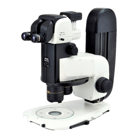
Page 103: Smz25 Zooming Body
Zoom is controlled by the P2-CTLA Control Box. Control signals are sent to the SMZ25 via a motorized focus unit or relay box. The zoom information is sent to the control box via a motorized focus unit or relay box, and then transmitted to the DS-L4 camera control unit or personal computer. - Page 104 Chapter 8 Functions and Operations of the Devices Image zooming Upper zoom button Images can be zoomed in and out using the zoom buttons on (magnification increase) the remote controller. Upper zoom button: Magnification increase Lower zoom button (magnification Lower zoom button: Magnification decrease FL Cube FL Cube...
- Page 105 Chapter 8 Functions and Operations of the Devices Useful zoom operation functions (ALZ function) When the objective is switched, the zoom magnification is automatically changed so that the field of view is maintained as it was. This prevents the target image from moving or disappearing and FL Cube FL Cube makes it possible to observe the image while increasing or...
-
Page 106: Focus Units, Focus Mount
The P2-FU Focus Unit consists of a square-type support pillar and a focus mount with the coaxial coarse/fine focusing system. The focus mount is attached with the SMZ18 or SMZ25 Zooming P2-FU Focus Unit Body through the P2-RNI2 Intelligent Nosepiece or the P2-FM... -
Page 107: P2-Mfu Motorized Focus Unit
The P2-MFU Motorized Focus Unit consists of a square-type support pillar and a focus mount with the motorized focusing system. The focus mount is attached with the SMZ18 or SMZ25 Zooming Body through the P2-RNI2 Intelligent Nosepiece or the P2-FM Focus Mount Adapter. The square-type support pillar is... - Page 108 Chapter 8 Functions and Operations of the Devices Focus knobs on the remote controller Turning the knob backward: Upward movement of the focus mount Turning the knob forward: Downward movement of the focus mount • Focusing stroke: 100 mm Pedals of the foot switch Left rear pedal: Upward movement of the focus mount Left front pedal: Downward movement of the focus mount For details about the pedal operations, see “10.2 AZ-FSW Foot Switch”...
- Page 109 Functions and Operations of the Devices Focus knob of the P2-MFU Motorized Focus Unit The focus knob of the P2-MFU Motorized Focus Unit attached with a cover cannot be used. This knob is to be used by Nikon during maintenance.
-
Page 110: P2-Fmdn Focus Mount
Chapter 8 Functions and Operations of the Devices P2-FMDN Focus Mount The P2-FMDN Focus Mount used exclusively for the SMZ18 can be attached to various types of stands with a 32-dia support pillar. Focus mount Restriction Upward movement Microscope systems including the P2-FMDN Focus Mount cannot be combined and used with the P2-EFLM Motorized Epi Focus knob Fluorescence Attachment. - Page 111 Chapter 8 Functions and Operations of the Devices Cable clamps Four cable clamps and four fixing screws (pan-head M4-8 mm) are supplied with the P2-FMDN Focus Mount. The cable clamps are used for clamping the P2-RLYC Relay Cable clamps LIS TED SM Z Cable or the fibers of the P2-CIA Coaxial Epi Illuminator to the...
-
Page 112: Nosepiece, Focus Mount Adapter
Chapter 8 Functions and Operations of the Devices Nosepiece, Focus Mount Adapter P2-RNI2 Intelligent Nosepiece The P2-RNI2 Intelligent Nosepiece is a nosepiece that connects the zooming body and the focus unit. Two objectives can be attached. The attached objectives can be switched by turning the Nosepiece nosepiece. -
Page 113: Objectives
Chapter 8 Functions and Operations of the Devices Objectives The microscope system supports the following objectives. Attach the objectives to the zooming body or intelligent nosepiece. Model name P2-SHR Plan Apo 0.5X P2-SHR Plan Apo 1X P2-SHR Plan Apo 1.6X P2-SHR Plan Apo 2X Magnification 0.5x... -
Page 114: Bases, Stands, And Stages
Chapter 8 Functions and Operations of the Devices Bases, Stands, and Stages Bases are used in combination with the P2-FU Focus Unit or the P2-MFU Motorized Focus Unit. There are three types of bases: Two with the illumination function and one without the illumination function. Each stand consists of a base and a support pillar. -
Page 115: P2-Dbl Led Diascopic Illumination Base
Chapter 8 Functions and Operations of the Devices Screw holes for attaching optional devices 20 100 The base’s top board has screw holes for attaching various 4-M5 types of devices. Screw holes are not penetrating Depth 7 to prevent ingress of solution into the base. 2-M4: Positioned under the stage plate attachment section of the base. -
Page 116: P-Ps32 Plain Stand
Combine this stand with an SMZ18 via a P2-FMDN Focus Mount. This stand cannot be used in combination with an SMZ25. This stand is equipped with a stage plate with black and milky white surfaces. Select the surface appropriate for the sample. -
Page 117: P-Dsl32 Led Diascopic Illumination Stand
Chapter 8 Functions and Operations of the Devices P-DSL32 LED Diascopic Illumination Stand See “8.3 P-DSL32 LED Diascopic Illumination Stand” in this chapter. P-DSF32 Fiber Diascopic Illumination Stand See “8.4 P-DSF32 Fiber Diascopic Illumination Stand” in this chapter. P-SXY64 XY Stage This stage shifts the glass plate in the X and Y directions when the X/Y shift knobs are turned. -
Page 118: C-Ssl Dia Sliding Stage
Chapter 8 Functions and Operations of the Devices C-SSL DIA Sliding Stage This stage enables fine movement of a sample when its side is pushed. Place the C-SSL DIA Sliding Stage on the base or the stand from which the stage place was moved, and then mount the removed C-SSL DIA Sliding Stage stage plate on the C-SSL DIA Sliding Stage.. -
Page 119: Tubes
Chapter 8 Functions and Operations of the Devices Tubes This microscope system can be used with the tubes listed in the table below. Attach the 10x, 15x, 20x, or 30x eyepiece to the binocular sleeve. Then, attach a camera such as a DS camera to the vertical tube using an adapter. -
Page 120: Episcopic Illuminator
The type of objectives used for the coaxial epi illuminator and the recommended zoom magnification are shown below. Usable objectives and recommended zoom magnifications Zoom magnification Objective SMZ18 Zooming Body SMZ25 Zooming Body P2-SHR Plan Apo 0.5X From 3.8x From 2.5x P2-SHR Plan Apo 1X From 4.0x From 4.0x... -
Page 121: C-Fdf Flexible Double Arm Fiber Illumination Unit
Chapter 8 Functions and Operations of the Devices C-FDF Flexible Double Arm Fiber Illumination Unit The C-FDF is a fiber connected to the C-FLED2 LED Light Source for Fiber Illuminator for illuminating samples. To C-FLED2 LED Light Source for Two fibers are held by the C-FIDH Fiber Holder. The orientation of Fiber Illuminator the holder’s arm can be adjusted so that the tips of the fibers face the samples for illumination. -
Page 122: Diascopic Illuminator
Chapter 8 Functions and Operations of the Devices Diascopic Illuminator As the primary diascopic illuminator for this microscope system, there are two types of bases and two types of stands equipped with the illumination optical system. A dark-field illuminator and a polarizing illuminator are also usable. P2-DBL LED Diascopic Illumination Base The P2-DBL is an illumination base equipped with diascopic illumination optical systems. - Page 123 Chapter 8 Functions and Operations of the Devices • LED brightness control selection switch, on: Assigns the control right to the control box. • LED brightness control selection switch, off: Assigns the control right to the base. For details about the control box, see “11.1, P2-CTLB Control Box” and “11.2, P2-CTLA Control Box.” ...
-
Page 124: P2-Dbf Fiber Diascopic Illumination Base
Chapter 8 Functions and Operations of the Devices Screw holes for attaching optional devices 20 100 The base’s top board has screw holes for attaching various 4-M5 types of devices. Screw holes are not penetrating Depth 7 to prevent ingress of solution into the base. 2-M4: Positioned under the stage plate attachment section of the base. - Page 125 Chapter 8 Functions and Operations of the Devices OCC (oblique coherent contrast) illumination This device supports OCC illumination so that a transparent sample can be observed at high contrast using diascopic illumination with a white LED. OCC illumination is an oblique illumination method suitable for observing the phase objects, where a sample is obliquely illuminated with a coherent illuminating light by shielding a part of the optical path using a shading plate.
-
Page 126: P-Dsl32 Led Diascopic Illumination Stand
Combine this stand with an SMZ18 via a P2-FMDN Focus Mount. This stand cannot be used in combination with an SMZ25. The base with a large glass plate (180 mm dia.) enhances usability and enables easier observation of samples in a container such as a petri dish. - Page 127 Chapter 8 Functions and Operations of the Devices Power supply and illumination control Power to the P-DSL32 LED Diascopic Illumination Stand is supplied by connecting a P2-CTLB Control Box or a 12 V AC adapter. To provide diascopic illumination without using a control box, connect a 12 V AC adapter. Turn on or off the LED diascopic illuminator using the LED power ON/OFF switch at the front of the base.
- Page 128 Chapter 8 Functions and Operations of the Devices Attachable optional devices The following devices can be attached to this stand: • P-SXY64 XY Stage • C-SSL DIA Sliding Stage • P-DF2 LED Dark Field Unit 2 • C-TRS Tilting Stage •...
-
Page 129: P-Dsf32 Fiber Diascopic Illumination Stand
Combine this stand with an SMZ18 via a P2-FMDN Focus Mount. Stage plate This stand cannot be used in combination with an SMZ25. fixing screw The base with a large glass plate (180 mm dia.) enhances usability and enables easier observation of samples in a container Stage such as a petri dish. - Page 130 Chapter 8 Functions and Operations of the Devices Usable objectives and recommended zoom magnifications Zoom magnification Objective Bright-field diascopic OCC illumination illumination 0.5X and condenser lens for low magnification From 1.5x Contrast in the field of view is not uniform. 1X and condenser lens for low magnification Entire area From 3.0x...
-
Page 131: P-Df2 Led Dark Field Unit 2
Chapter 8 Functions and Operations of the Devices Exchange for a C-EP support The support length is 145 mm longer than standard when the original support for this stand is exchanged for a C-EP support. This is useful for attaching the focus mount to a high position. -
Page 132: Epi-Fluorescence Attachment
Chapter 8 Functions and Operations of the Devices Epi-Fluorescence Attachment The microscope system can be used with the status detection model P2-EFLI Epi Fluorescence Attachment and Motorized P2-EFLM Epi Fluorescence Attachment. P2-EFLI Epi Fluorescence Attachment This illuminator is attached between the zooming body and the BIN O tube. - Page 133 Also, duplicated images may be produced by the internal half mirror. OCC light shielding plate When using an epi-fluorescence attachment with a diascopic illumination base, Nikon recommends closing the OCC light shielding plate on the dia-illumination completely. This can decrease background noise caused by intrinsic fluorescence in the diascopic illuminator.
-
Page 134: P2-Eflm Motorized Epi Fluorescence Attachment
Chapter 8 Functions and Operations of the Devices P2-EFLM Motorized Epi Fluorescence Attachment The motorized epi-fluorescence illuminator is attached between Filter cube indication the zooming body and tube. A HG precentered fiber illuminator is label used as the light source. The light coming from the light source is (label attachment led into the device by the HG fiber and then passed through the position) - Page 135 Also, duplicated images may be produced by the internal half mirror. OCC light shielding plate When using an epi-fluorescence attachment with a diascopic illumination base, Nikon recommends closing the OCC light shielding plate on the dia-illumination completely. This can decrease background noise caused by intrinsic fluorescence in the diascopic illuminator.
-
Page 136: Remote Control Devices
Chapter 8 Functions and Operations of the Devices Remote Control Devices A remote controller, foot switch, and photo release are available as remote control devices of the microscope system. P2-RC Remote Controller 10.1 The P2-RC Remote Controller is used mainly for focus and zoom operations. The remote controller is attached to the REMOTE connector of the P2-CTLA Control Box. - Page 137 ALZ button Activates the ALZ function. To deactivate the ALZ function, press the button again. For the ALZ function, see “ Useful zoom operation functions (ALZ function)” in “1.2 SMZ25 Zooming Body” in this chapter. (18) ALZ ON/OFF indicator The LED lights when the ALZ function is activated.
-
Page 138: Az-Fsw Foot Switch
Chapter 8 Functions and Operations of the Devices LCD indications 1st page 1: Total magnification (zoom magnification x objective magnification x eyepiece magnification) (Example) [MAG: 236.25x] 2: Zoom magnification (Example) [ZOOM: 15.75x] 3: Objective magnification (Example) [OBJ: 0.75x] 4: Eyepiece magnification (Example) [EP10x] 5: Diascopic LED light intensity (Example) [LEDDIA ... - Page 139 • The speed changes based on the magnification and nosepiece address. (See the table below.) • If a nosepiece address has not been set, the unit moves at the maximum speed. Coarse SMZ25 0.63 to 5.0 5.1 to 10.0 10.1 to 15.75...
-
Page 140: Az-Pcr Photo Release
Chapter 8 Functions and Operations of the Devices AZ-PCR Photo Release 10.3 The AZ-PCR Photo Release is a foot switch for capturing images Connection cable using the DS camera connected to the microscope. The photo release is connected to the PHOTO connector of the AZ-FSW Foot Switch. -
Page 141: Control/Communication Devices And Relay Devices
Chapter 8 Functions and Operations of the Devices Control/Communication Devices and Relay Devices P2-CTLB Control Box 11.1 Power LED Power switch P2-CTLB Control Box When electrically connected to the following devices, the P2-CTLB Control Box can detect the device states and handle communications: Device Operation... - Page 142 Chapter 8 Functions and Operations of the Devices Connector names and connection destinations The figure below shows the connectors on the rear of the control box and the connection destinations: (Connect to the USB port of a personal computer or DS-L4.) LEDDIA (Connect to the LED light control terminal of the P2-DBL LED...
-
Page 143: P2-Ctla Control Box
P2-RC Remote Controller Communications (10) AZ-FSW Foot Switch Detects the switch states, moves the P2-MFU Motorized Focus Unit vertically, and adjust the magnification of the SMZ25 Zooming Body. (11) AZ-PCR Photo Release Detects the switch states and captures images. (12) C-HGFIE HG Precentered Fiber Illuminator Switches the ND filter and opens/closes the shutter. -
Page 144: P2-Rly Relay Box
Intelligent Nosepiece.) ZOOM and DIA + EPI-FL System", step 5 "Attach a relay box." (P2-FU (Connect to the SMZ25/SMZ18 Focus Unit system only" and Chapter 3, "3.2 Compact System Zooming Body.) Assembly", step 4 "Attach a coaxial epi illuminator (in the... -
Page 145: Troubleshooting
If you detect problems that are not listed in the table or the problem still persists even after the indicated measures are taken, turn off the device and contact your nearest Nikon representative. -
Page 146: Image Viewing
Chapter 9 Troubleshooting Image Viewing Problem Cause Measure Devices are not attached correctly. Attach the devices correctly. The optical path switching lever of the tube is Position the lever correctly. positioned partway. Part of the field of view is missing. Firmly turn the nosepiece to the click position for The nosepiece is not turned to the click The field of view is... -
Page 147: Motorized Devices
Chapter 9 Troubleshooting Motorized Devices Problem Cause Measure The product cannot be The power cable is not connected. Connect the power cable properly. turned on. Check the connections between the AC adapter The power of the P2-CTLA Control Box is not and the P2-CTLA Control Box, and then move the Operating the remote turned on or the AC adapter is not connected. - Page 148 This symbol is provided for use in the People’s Republic of China, for environmental protection in the fi elds of electronic information products.
- Page 149 Nikon Europe B.V. Stroombaan 14, 1181 VX Amstelveen, The Netherlands tel. +31-20-7099-000 060-0001 13-4 FWD United Kingdom 011 281-2535 Nikon UK, Branch of Nikon Europe B.V. 1 The Crescent, Surbiton, Surrey, KT6 4BN, United Kingdom tel. +44-208-247-1717 980-0014 1-1-1 Switzerland 022 263-5855 Nikon Europe B.V., Amstelveen, Zweigniederlassung...