Table of Contents
Advertisement
Advertisement
Table of Contents

Related Manuals for Nikon SMZ645


Summary of Contents for Nikon SMZ645
- Page 1 M219 E 06.2.NF.4 Stereoscopic Zoom Microscope SMZ645/ SMZ660 Instructions...
-
Page 3: Warning/Caution Symbols Used In This Manual
Warning/Caution Symbols Used in This Manual Though Nikon products are designed to provide you with the utmost safety during use, incorrect usage or disregard of the instructions may cause personal injury or property damage. For your own safety, read the instruction manual carefully and thoroughly before using the product. -
Page 4: Be Sure To Always Follow These Guidelines
2. Do not disassemble Disassembly may result in damage to the instrument. Never disassemble any part except as described in this operation manual. Contact your Nikon representative if you notice any malfunction of this instrument. 3. Check the input voltage... -
Page 5: Caution
CAUTION 1. Caution when replacing lamps The lamp and the surrounding area become very hot during and immediately after using the illuminator. Be careful not to burn yourself. In addition, when replacing a lamp be sure the lamp has cooled sufficiently. 2. - Page 6 1. Installation location Note the following points when installing the stereoscopic microscope. • Install the microscope in a location with the temperature between 0° and 40°C, and humidity of less than 80%. If installed in a hot and humid location, mold may form on the lenses or condensation may occur inside, resulting in reduced performance or damage to the microscope.
- Page 7 During storage, place a plastic cover over the equipment to prevent dust accumulation. 6. Regular inspections Regular inspections are recommended in order to maintain peak performance. Please consult your Nikon representative for details about regular inspections.
-
Page 9: Table Of Contents
Contents Warning/Caution Symbols Used in This Manual ......1 Be sure to always follow these guidelines........2 WARNING .................... 2 CAUTION ..................... 3 Nomenclature ................... 8 Assembly ..................10 Usage ....................12 1 Preparations For Observation ............12 1. Adjust the torque of the focus knob........12 2. -
Page 10: I Nomenclature
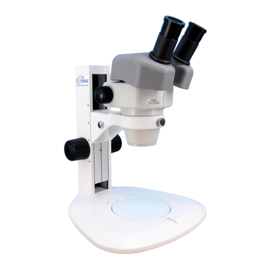
Nomenclature The illustration shows the combination of SMZ645 zooming body, C-W10X eyepieces and C-PS plain focusing stand. Eyepiece Sleeve 10X, 15X, 20X and 30X eyepieces are available. Zooming knob Changes the Diopter ring magnification of the sample image. Refer to “1-3. Adjust the Refer to “3. - Page 11 Zooming knob clicks ON/OFF screw (inside) Refer to “ON/OFF of the Zooming Knob Clicks” on p.14 Hexagonal wrench Eyepiece inclination hanger SMZ645: 45° from the horizontal Holds the supplied SMZ660: 60° from the hexagonal horizontal wrenches. Hexagonal wrench (Large) Screw hole for mounting an...
-
Page 12: Assembly
Assembly Place the stand on the level surface. Mount the stage plate. Fit the stage plate into the stand base while pushing it against the rim in the direction shown by the arrow in the illustration. The stand arm can be lowered. (If you Groove do not need to lower the arm, jump to step 4.) - Page 13 Insert the eyepieces into the eyepiece sleeves. Be sure that it is inserted all the way until it touches the end of the sleeve. Note) When inserting the 10X eyepiece, assure that it touches the end of the sleeve, because the rubber cover of the 10X eyepiece will obstruct the view of the sleeve end.
-
Page 14: Usage
Usage Preparations For Observation Increasing the torque. Adjust the torque of the focus knob. Adjust the torque of the focus knob so as not to fall down the zooming body on its own weight. (To reduce the torque, turn the knob in the direction opposite to the arrow.) Adjust the interpupillary distance. -
Page 15: Focusing
The distance between the focus plane and the bottom surface of the zooming body is called “the working distance”. Since the working distance of the SMZ645 and SMZ660 is 115 mm, the focusing will become easier if you set the zooming body at the position where its bottom surface is 115 mm apart from the sample surface. -
Page 16: Zoom
Zoom Change the zooming magnification. Turning the zooming knobs on the left and right side of the zooming body will change the magnification of the sample image. ■ Total Magnification The zooming knob on the right has the indication of the zooming magnification. -
Page 17: If You Cannot Focus On The Sample Though The Zooming Body Is At The Highest Position
Usage If You Cannot Focus On The Sample Though The Zooming Body Is At The Highest Position. When you use the 0.5X auxiliary objective or observe a tall sample, you may not be able to focus on the sample though turning the focus knob to raise the zooming body to its highest position. -
Page 18: Using Accessories
Using Accessories Reticles Your reticles may be attached to the eyepiece. Once remove the field ring (or lens room of the 20X and 30X) from the eyepiece. Attach the reticle with its pattern surface facing down to the eyepiece and reattach the field ring (or lens room). -
Page 19: Al Erg (Ergo) Auxiliary Objective
AL ERG (ERGO) Auxiliary Objective Using the AL ERG auxiliary objective allows you to continuously change the eye level through a 40 mm range. Milled ring 1 Rotate the milled ring on the AL ERG to Eye level attach it to the zooming body. scale 2 Rotate the focus knobs on the focusing Rotation... -
Page 20: Sm-S4L 4 X 4 Stage L
SM-S4L 4 X 4 Stage L SM-S4L 4 X 4 stage L may be attached by Stage 4 X 4 stage clamp screw using the C-4SA stage adapter. In this case, use the C-ER auxiliary adapter because the position of the sample will become higher. (Refer to “4. -
Page 21: Halogen Illuminators
Using Accessories Halogen Illuminators There are two illuminators available: the G-LS of 6V 10W and the C-DSLS of 6V 20W. G-LS Lamp Socket A (6V10W) Lamp house Lamp socket Plug (may be moved back and forth) Mounting screw C-DSLS Illuminator A (6V20W) Lamp house Plug Lamp socket... -
Page 22: Lamp
Lamp CAUTION The lamp and the surrounding area become very hot during and immediately after using the illuminator. Be careful not to burn yourself. In addition, be sure the lamp has cooled sufficiently before replacing a lamp. Pull the lamp socket from the lamp house and G-LS insert the lamp straight into the socket as far as it will go. -
Page 23: Attaching To The Stand (Only For G-Ls)
Using Accessories lamp, handle it through a piece of cloth or through its packaging until replacement is complete. If you get fingerprints on the lamp, wipe gently with a piece of clean cloth dampened with alcohol. Attaching to the stand (only for G-LS) Set so that the protrusion on the lamp house G-LS aligns with the inside of the screw hole on the... - Page 24 2 Epi arm Slightly loosen the clamp knob on the Clamp knob Simultaneously arm. Screw in the mounting screw at clamps two the end of the Epi arm into the screw arms/joints. hole of the stand (screw hole for Joint mounting an Epi-arm) while turning the joint.
-
Page 25: Power Supplies
Check that the voltage displayed matches the Fuse voltage used in your area. If the voltages do not match, do not use the power supply and Always use the fuse contact your Nikon representative. specified. (Rear view) Power cord Output connector... - Page 26 Power Supply XN A (only for regions with 100/120 V power) Input rating Power supply for 100V regions only: 100 V AC, 50/60 Hz, 30 W Power supply for 120V regions only: 120 V AC, 50/60 Hz, 30 W Output rating 3-6 V AC, 3.3 A Fuse rating 250 V, 1 A...
-
Page 27: Lighting Area Adjustment (Only For G-Ls)
• C-US1 and C-US2 Universal Table Stands Airtight Feature The SMZ645, the SMZ660 and the C-W 10X eyepieces are made airtight. This feature may be convenient when using the microscope in the oil- misty environment in the factory or for soldering. -
Page 28: Table 1: Total Magnification And Real Field
Table 1: Total Magnification and Real Field... -
Page 29: Table 2: Observable Sample Heights
Table 2: Observable Sample Heights Table 2: Observable Sample Heights (C-PS/C-PSC plain focusing stand + C-DS diascopic stand) [mm] Auxiliary Arm normal Arm lower When using objectives position position auxiliary adapter None 0 ~ 103 0 ~ 48 55 ~ 159 AL 0.29 X —...