
Related Manuals for NARGESA H3


Summary of Contents for NARGESA H3
- Page 1 GAS FORGE INSTRUCTIONS BOOK PRADA NARGESA, S.L Ctra. de Garrigàs a Sant Miquel s/n · 17476 Palau de Santa Eulàlia (Girona) Spain Tel. +34 972568085 · nargesa@nargesa.com · www.nargesa.com...
- Page 2 Thank you for choosing our machines www.nargesa.com...
-
Page 3: Table Of Contents
INDEX 1. MACHINE INFORMATION ....................... 3 1.1. Identification of the machine …................3 1.2. Dimensions ....................... 3 1.3. Description of the machine …..................3 1.4. Fuel for the furnace ....................4 1.5. Identification of elements ..................5 1.6. Description of elements ……..................6 1.6.1. -
Page 4: Machine Information
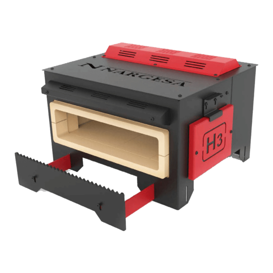
Picture 1. External dimensions of the Furnace H3 1.3. Machine description. The H3 Furnace is an oven designed to heat metal profiles of different thicknesses and shapes. The furnace H3 allows us to heat parts up to a temperature of 1300ºC. -
Page 5: Fuel For The Furnace
GAS FORGE H3 1.4. Fuel to be used with this foerge COMPOSITION AND INFORMATION: PROPANE GAS G.L.P. Chemical nature Blend of Hydrocarbones Synonyms Gas de cocina - Gas licuado de petróleo Ingredients Propane Butane Ethane Penthane IDENTIFICATION OF HAZARDS Main hazards... -
Page 6: Identification Of Elements
1.5. Identificación de los elementos Upper fixing Lower fixing device for device for burners burners Burner 3 Burner 2 Burner 1 Ignition Closing chamber Sparks plug holder Upper cove Material holder Side cover Control panel Wáter hose Gas inlet Information plate fitting Pressure gauge Presure control... -
Page 7: Description Of Elements
Side opening Picture 2. Furnace openings 1.6.2. Burners The burners of Nargesa’s Furnaces has been manufactured by Nargesa and designed exclusively to be used on the furnaces H1, H2 and H3. - Type of burner: Athmospheric - Maximum supply pressure: 1,5 Bar... -
Page 8: Thermocouple
1.6.3. Thermocouple The thermocouple is the sensor to measure the temperature. It consists of two different metals, joined at one end. When the union of the two metals is heated or cooled, it produces a voltage proportional to the tempera- tura which causes the safety valve to open or close. -
Page 9: General Features
GAS FORGE H3 Picture 5. Information plate 1.7. Main features Dimensions of combustion chamber 464x240x100 mm Maximum temperature 1300 ºC Nr of burners Type of fuel Propane gas (GLP) Adjustable working pressure 0.1-1.5 bar Power (Hi) 12 kW Gas intake as 1 per bar... -
Page 10: Transport And Storage
2. TRANSPORT AND STORAGE 2.1. Transport Carrying of the furnace must be done by two people, holding it by the lower side of it and lifting it with both hands. Do not transport the furnace in any other way since it could be damaged. WARNING: In order to move the gadget it is necessary that all burners a re OFF and wait 24 hours to make sure the isolating material is at room temperature. -
Page 11: Maintenance
- It is recommended to check the status of the thermocouple, the ignition device, the gas valve, the regulator and the non-return valve. If any of these elements suffers any type of deterioration, contact the Nargesa technical service. -
Page 12: Change Of The Insulating Material Of The Furnace
3.2. Change of the insulating material of the oven To remove the insulating material from the oven we will follow the following instructions: WARNING: To proceed with the change of insulating material it is necessary to turn off the Burners and wait 24 hours to ensure that the insulating material is at room temperature 1. - Page 13 GAS FORGE H3 5. Remove the thermocouple and the spark 6. Take off the 4 bolts and nuts that hold the plugs by pull away the three bolts Control Panel. Remove the Control panel, the thermocouple and the spark plugs 7.
- Page 14 11. Remove the rear insulation panels 12. Remove the front holders of the upper plate 13. Remove the lower insulation 14. Slide the lower insulation towrads the back part of the furnace and remove them by the upper side. 15. Remove the side insulations 16.
- Page 15 GAS FORGE H3 We will use this process in reverse order to do the placement of the insulation: 1. Place the front insulation 2. Place the side insulation 3. Place the lower insulation by the upper/ rear 4. Place the front holders of the upper plate side of the furnace and slide them towards the front part.
- Page 16 7. Place the Side doors. Assemble the Lower 8. Place the Spark plug holder and the three fastener of the burners by tightening the burners adjusting the Lower burner fixer so four screws and the four nuts that hold it that the end of the Burner is aligned with the 9.
-
Page 17: Handling Book
GAS FORGE H3 4. HANDLING MANUAL We have a Control panel which will allow us to control the performance of the furnace H3 and which will enable us to maintain complete control of the m¡achine in a simple and intuitive way. -
Page 18: Installation And Set Up
5. INSTALLATION AND SET UP 5.1. Machine location The am is to locate the furnace properly to avoid having to move it; otherwise, the user must follow the guideli- nes described in the transport section (nº2). It should be placed on a smooth and levelled surface to avoid any movement of it during the positioning of the profiles. -
Page 19: Set Up
- Verify that the maximum gas inlet pressure is less than 25 bars. - Connect the Adapter to a LPG propane gas cylinder The Pressure Regulator and Gas Hose supplied by Nargesa will always be used 5.5. Openings There are two side openings to work with longer materials. -
Page 20: Adjustment Of The Material Support Position
5.6. Adjustment of the material support position The oven is equipped with a Material holder, this support serves to hold the material while warming up. The support point of the material can be regulated by moving the support. The point of support must be adjusted according to the length of the material. -
Page 21: First Set Up Of Furnace
5.7. First set up of furnace For the first start-up of Nargesa gas furnaces, the automatic ignition provided is not used. We will use an external device to light the burner flame. For example a long lighter or a blowtorch. - Page 22 Open Valve 11. Increase the gas pressure Open Valve progressively to the maximum. progressively up to 1 bar. progressively to the maximum. If the model is H2. Open Valve 14. After 30 minutes, stop the 15. Close the gas valves. progressively to the maximum.
-
Page 23: Ignition Of The Furnace
4. Verify that all gas connections between the bottle and the furnace are correctly connected and the¡at there is no leak. 5. Checkup that the gas work pressure is between 0,1 and 1,5 bars. (Pressure recommended by Nargesa: 0,2 to 1 bar). -
Page 24: Possible Breakdowns
Clean up the furnace air inlet. The flame goes Excessive gas pressure Reduce the gas pressure out of the combustion chamber If the problem goes on, please contact our technical assistance in Nargesa +34 972568085 +34 620446827 sat2@nargesa.com sat2.nargesa - 23 -... -
Page 25: Warnings
GAS FORGE H3 7. WARNINGS The H3 furnace is designed so that the operator can adjust the machine and heat the necessary parts with total safety. Any modification of the machine will alter the security that it offers, breaching the certificate of conformity and being able to generate irreparable personal and material damages. - Page 26 Tecnichal Annex Furnace H3 List of parts Gas layout...
- Page 27 List of parts - A3 -...
- Page 28 GAS FORGE H3 - A4 -...
- Page 29 - A5 -...
- Page 30 GAS FORGE H3 - A6 -...
- Page 31 - A7 -...
- Page 32 GAS FORGE H3 - A8 -...
- Page 33 Gas layout - A9 -...
- Page 34 OUR RANGE OF MACHINERY IRON WORKERS SECTION BENDING NON-MANDREL HORIZONTAL PRESS MACHINES PIPE BENDER BRAKE TWISTING/SCROLL HYDRAULIC PRESS HYDRAULIC SHEAR BENDING MACHINES BRAKES MACHINES IRON EMBOSSING END WROUGHT IRON GAS FORGES MACHINES MACHINES BROACHING POWER HAMMERS PRESSES FOR LOCKS MACHINES...