
Related Manuals for NARGESA BM25


Summary of Contents for NARGESA BM25
- Page 1 VERTICAL BROACHER BM25 INSTRUCTIONS BOOK PRADA NARGESA, S.L Ctra. de Garrigàs a Sant Miquel s/n · 17476 Palau de Santa Eulàlia (Girona) SPAIN Tel. +34 972568085 · nargesa@nargesa.com · www.nargesa.com...
- Page 2 Thank you for choosing our machines www.nargesa.com...
-
Page 3: Table Of Contents
ÍNDEX 1. GENERAL INFORMATION ...................... 4 1.1. General dimensions ....................4 1.2. Layout ……………………………………………………………………….……………….. 4 1.3. Description of the machine ..................4 1.4. Identification of the machine ..................5 1.5. General characteristics ....................6 1.6. Description of safety devices ..................7 1.7. -
Page 4: General Information
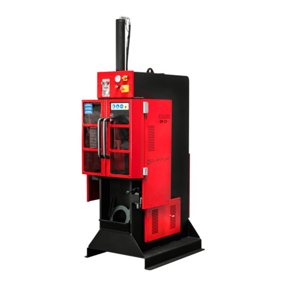
1.2. Layout 1.3. Description of the machine Hydraulic Broaching machine BM25 NARGESA has been fabricated in a welded and mechanized steel monoblock. It's a machine useful for making notches and keyways in all kinds of pieces: sprockets, pulleys, gears, etc... -
Page 5: Identification Of The Machine
1.4. Identification of the machine Piston Broach Control panel Thick part (shim) Front protection Bushing Shavings drawer Side protection Piston up/down handle Electric motor Hydraulic container - 5 -... -
Page 6: General Characteristics
VERTICAL BROACHER BM25 1.5. General characteristics Motor power 2,2 KW / 3 HP Tensión 230/400V Three-Phase 50/60 Hz Hydraulic power 10 Tm Working speed 24 mm/s Return speed 54 mm/s Pump Flow 7,5 L Shank displacement 600 mm Goosneck 300 mm... -
Page 7: Description Of Safety Devices
1.6. Description of safety devices The safety devices the broaching machine has got are the ones listed below: - The door is located at the front part of the machine to prevent from any projected part could injure the operator. This door has a safety system which only allows any movement of the machine when the door is closed. -
Page 8: Operative Working Place
VERTICAL BROACHER BM25 1.10. Operative working place The broaching machine will only be used by an operative at the time who will be placed in front of the ma- chine, never at a lateral of it because he ought to control the whole set of the machine. Moreover the ma- chine main protection devices are thought for the frontal use of the machine. - Page 9 3. Remove the bolts of the support 4. Remove the bolts that fix the piston to the stand 5. We start the machine with the main switch 6. We carefully press the lever down so that the (1), the pump with the green button (2) and can- rod makes pressure on the table and the piston cel the safety with the key (3).
- Page 10 VERTICAL BROACHER BM25 7. When the piston is in its highest position, we 8. With the activation lever we put the piston up fasten the upper fixing bolts until we can remove the support - 10 -...
-
Page 11: Transport And Storage
2. TRANSPORT AND STORAGE 2.1. Transport Transport without lifting will be carried out by a forklift truck. Lifting will be carried out by a crane using the clamping spots for it. 2.2. Storage conditions The broaching machine could never be stored in a place that does not fulfil the following requirements: * Humidity between 30% and 95% without water condensation. -
Page 12: Maintenance
VERTICAL BROACHER BM25 3. MAINTENANCE 3.1. General maintenance - Every 500 hours of use, check the oil level in the tank. In the front of tank is oil level. In the absence of oil, fill until the level cap show 3/4 full. -
Page 13: Instalment And Starting Up
4. INSTALMENT AND STARTING UP 4.1 Instructions to fix it When the machine is put down by a crane it is necessary to place it down correctly so it doesn’t have to be moved once it is on the floor. In case it is not possible, then a moveable base must be placed below aways caring for its inclination to avoid any possible turn over. -
Page 14: Changing Connection Of The Converter Primary
VERTICAL BROACHER BM25 4.4.1. Changing connection of the converter primary Depending on the voltage available at the outlet it will be also required to change the connection of the converter primary which is fixed to the electrical panel inside the the machine box. -
Page 15: Operation Manual
5. OPERATION MANUAL 5.1. Control panel Tabla de Pressure Presure Voltage Alarm Main switch capacidades regulator gauge indicator indicator Start/Stop Safety Emergency button stop button 5.2. Methods and stop systems of the machine Pump stop: In order to stop only the pump, press the red button “PARO”. With the pump stopped, the piston movement is cancelled. -
Page 16: Samples To Make A Correct Broaching Operation
VERTICAL BROACHER BM25 5.3. Samples to make a correct broaching operation 1 - Place the piece in the middle of the table. 2 - Insert the bushing. 3 - Place the broach in the bushing, lubricate abundantly in order to achieve a perfect broaching opeartion, especially during the first operation. -
Page 17: Samples To Make Cotter Slots
5.4. Samples to make cotter slots 1. Place the bushing on the 2. Place the broach. First 3. Get the piston down part pass With just the broach 4. Place the thick part 5. Place the broach 6. Get the piston down 7. -
Page 18: Table Of Characteristics Of Brushes
VERTICAL BROACHER BM25 6. TABLE OF CHARACTERISTICS OF BRUSHES 6.1. Millimeter keyway broaches - 18 -... - Page 19 6.2. Inches keyway broaches - 19 -...
- Page 20 VERTICAL BROACHER BM25 - 20 -...
-
Page 21: Formules For Broaching
7. FORMULES FOR BROACHING Picture 1 Picture 2 Picture 3 Finished part Broach 18mm Height to mill Bushing Ø60 d = b + h 1. Mechanize bushing (Picture 1) 2. Take the measurement of the tooth bottom of the brush. In this case the 18mm broach. (Picture 2) 3. -
Page 22: Accessoires
VERTICAL BROACHER BM25 8. ACCESSOIRES Millimeter keyway broaches Keyway broaches 25mm REF: 125-09-01-BR-00017 Tolerance JS9 (-0,027 +0,013) Model Broach dimensions 25,40 x 514,35mm Standard keys 25 x 14mm Min./Max. Cutting length 25,4mm / 152,4mm Required pressure 12.300Ibs / 5.579,18Kg Required shims/ Nr of passes... - Page 23 Keyway broaches 20mm REF: 125-09-01-BR-00014 Tolerance JS9 (-0,026 +0,015) Model Broach dimensions 25,40 x 514,35mm Standard keys 20 x 12mm Min./Max. Cutting length 25,4mm / 152,4mm Required pressure 8.800Ibs / 3.991,61Kg Required shims/ Nr of passes 3 shims / 4 passes Thickness 1,587mm Bushing diameter...
- Page 24 VERTICAL BROACHER BM25 Keyway broaches 14mm REF: 125-09-01-BR-00011 Tolerance JS9 (-0,023 +0,013) Model Broach dimensions 14,28 x 352,42mm Standard keys 14 x 9mm Min./Max. Cutting length 25,4mm / 152,4mm Required pressure 11.100Ibs / 5.034,87Kg Required shims/ Nr of passes 2 shims / 3 passes...
- Page 25 Keyway broaches 8mm REF: 125-09-01-BR-00008 Tolerance JS9 (-0,017 +0,013) Model Broach dimensions 9,52 x 298,45mm Standard keys 8 x 7mm Min./Max. Cutting length 9,921mm / 63,5mm Required pressure 3.680Ibs / 1.669,22Kg Required shims/ Nr of passes 2 shims / 3 passes Thickness 1,27mm Bushing diameter...
- Page 26 VERTICAL BROACHER BM25 Keyway broaches 5mm REF: 125-09-01-BR-00004 Tolerance JS9 (-0,014 +0,008) Model Broach dimensions 6,35 x 171,45mm Standard keys 5 x 5mm Min./Max. Cutting length 7,54mm / 42,862mm Required pressure 1.860Ibs / 843,68Kg Required shims/ Nr of passes 1 shim / 2 passes...
- Page 27 Keyway broaches 2mm REF: 125-09-01-BR-00001 Tolerance JS9 (-0,014 +0,009) Model Broach dimensions 3,175 x 127mm Standard keys 2 x 2mm Min./Max. Cutting length 5,159mm / 28,575mm Required pressure 720Ibs / 326,58Kg Required shims/ Nr of passes 0 shims / 1 pass Bushing diameter 6, 8, 10, 12 and 15mm Bushing length...
- Page 28 VERTICAL BROACHER BM25 Keyway broaches 3/4 inch REF: 125-09-01-BRP-00018 Tolerance JS9 (0,7515 · 0,7525) Model Broach dimensions 3/4 x 15 1/2 inches Min./Max. Cutting length 1 pulgada / 6 inches Required pressure 11.900Ibs Required shims/ Nr of passes 5 shims / 6 passes...
- Page 29 Keyway broaches 1/2 inch REF: 125-09-01-BRP-00015 Tolerance JS9 (0,5006 · 0,5016) Model Broach dimensions 9/16 x 13 7/8 inches Min./Max. Cutting length 1 inch / 6 pulgadas Required pressure 9.800Ibs Required shims/ Nr of passes 3 shims / 4 passes Thickness 0,0625 inches Bushing diameter...
- Page 30 VERTICAL BROACHER BM25 Keyway broaches 5/16 inch REF: 125-09-01-BRP-00012 Tolerance JS9 (0,3127 · 0,3137) Model Broach dimensions 9/16 x 13 7/8 inches Min./Max. Cutting length 1 inch / 6 inches Required pressure 8.000Ibs Required shims/ Nr of passes 2 shims / 3 passes...
- Page 31 Keyway broaches 1/4 inch REF: 125-09-01-BRP-00009 Tolerance JS9 (0,2502 · 0,2512) Model Broach dimensions 3/8 x 11 3/4 inches Min./Max. Cutting length 25/64 inch / 2 1/2 inches Required pressure 2.520Ibs Required shims/ Nr of passes 1 shim / 2 passes Thickness 0,0625 inches Bushing diameter...
- Page 32 VERTICAL BROACHER BM25 Keyway broaches 5/32 inch REF: 125-09-01-BRP-00006 Tolerance JS9 (0,1564 · 0,1574) Model Broach dimensions 3/16 x 6 3/4 inches Min./Max. Cutting length 19/64 inch / 1 11/16 inches Required pressure 1.320Ibs Required shims/ Nr of passes 1 shim / 2 passes...
- Page 33 Keyway broaches 1/8 inch REF: 125-09-01-BRP-00003 Tolerance JS9 (0,1252 · 0,1262) Model Broach dimensions 1/8 x 5 inches Min./Max. Cutting length 13/64 inch / 1 1/8 inches Required pressure 650Ibs Required shims/ Nr of passes 1 shim / 2 passes Thickness 0,0310 inches Bushing diameter...
- Page 34 Technical annex Vertical broacher BM25 List of parts Piston assembly Hydraulic group Electric map Hydraulic map...
- Page 35 VERTICAL BROACHER BM25 A1. List of parts - A3 -...
- Page 36 - A4 -...
- Page 37 VERTICAL BROACHER BM25 - A5 -...
- Page 38 - A6 -...
- Page 39 VERTICAL BROACHER BM25 - A7 -...
- Page 40 A2. Piston assembly - A8 -...
- Page 41 VERTICAL BROACHER BM25 - A9 -...
- Page 42 A3. Hydraulic group - A10 -...
- Page 43 VERTICAL BROACHER BM25 - A11 -...
- Page 44 - A12 -...
- Page 45 A4. Electric box - A14 -...
- Page 46 VERTICAL BROACHER BM25 - A15 -...
- Page 47 - A16 -...
- Page 48 VERTICAL BROACHER BM25 A5. Electric map - A17 -...
- Page 49 A5. Hydraulic map Filter Hydraulic Pump Electric motor Pressure Control (regulator) Solenoid “Bending” Main Manual Distributor Manometer valve Manometer - A18 -...
- Page 50 OUR RANGE OF MACHINERY IRON WORKERS SECTION BENDING NON-MANDREL HORIZONTAL PRESS MACHINES PIPE BENDER BRAKE TWISTING/SCROLL HYDRAULIC PRESS HYDRAULIC SHEAR BENDING MACHINES BRAKES MACHINES IRON EMBOSSING END WROUGHT IRON GAS FORGES MACHINES MACHINES BROACHING POWER HAMMERS PRESSES FOR LOCKS MACHINES...