
Related Manuals for NARGESA MX700


Summary of Contents for NARGESA MX700
- Page 1 IRONWORKER MACHINE MX700 INSTRUCTIONS BOOK PRADA NARGESA, S.L Ctra. de Garrigàs a Sant Miquel s/n · 17476 Palau de Santa Eulàlia (Girona) SPAIN Tel. +34 972568085 · nargesa@nargesa.com · www.nargesa.com...
- Page 2 Thank you for choosing our machines www.nargesa.com...
-
Page 3: Table Of Contents
4.3. Admissible outer conditions ..................4.4. Connection to power supply ..................5. OPERATION MANUAL ......................5.1. Introduction ......................... 5.2. Feeding up of MX700 ....................5.3. Activation of the machine .................... 5.4. Working at manual mode .................... 5.5. Working at automatic mode .................. -
Page 4: Features Of The Machine
1.2. Description of the machine The MX700, has been especially designed for punching metal parts with different shapes depending on the type of punch. It may have other utilities by incorporating various accessories. It may be used for other purposes but always following the manufacturer's guidelines, which provide all dockable accessories to the machine. -
Page 5: Identification Of The Machne
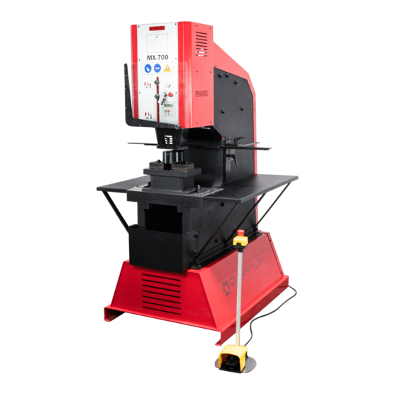
IRONWORKER MACHINE MX700 1.3. Identification of the machine Displacement Tension light Information display Operational keypad Extractor Support base for diez Emergency stop Pedal Clamping point General switch Bench for dies Ventilation grill Box door Electric engine Electro-distributor Safety valve Hydraulic circuit container... -
Page 6: General Characteristics
2000 Kg 1.5. Description of safety devices Protection devices of the MX700 are the extractor at the front of the machine to hold the material and avoid putting your hands between the punch and the workpiece. It also has a screen to prevent fragments projections, this display has a security system to prevent the punch from descending if the screen is raised, only if the key to cancel safety is turned, then it coul be possible to work with with the hazard light. -
Page 7: Transport And Storage
IRONWORKER MACHINE MX700 2. TRANSPORT AND STORAGE 2.1. Transport There are two ways of carrying out the transportation of the machine. One of them is lifting it by its lower part using a forklifting truck as indicated in picture 3 and the other one is by using a crane of forklifting truck as well and grabbing it by the clamping spot on the upper side, as indicated in picture 4. -
Page 8: Maintenance
3. MAINTENANCE 3.1. General maintenance Every 500 hours of use, check the oil level in the tank. At the top of the tank is the oil plug. In case you need to add oil, fill to cover the peephole in the front of the tank. -
Page 9: Installment And Starting Up
IRONWORKER MACHINE MX700 4. INSTALLMENT AND STARTING UP 4.1. Location of the machine Efforts will be made to locate the machine properly to avoid having to move, otherwise the user must follow the guidelines described in section transport (nº2). It should be placed on a flat, level surface to prevent vibration and movement of the joint while performing. -
Page 10: Connection To Power Supply
IMPORTANT: This machine must be connected to a single outlet with earthing The MX700 is equipped with a three phased engine 230V / 400V with 5,5Kw connected on a star shape to connect into a power supply of 400V. It should be connected to an only power supply with the indicated requirements. -
Page 11: Operation Manual
IRONWORKER MACHINE MX700 5. OPERATION MANUAL Compulsory safety devices when using the MX700 Tension light Safety cancelling light Key of cancelling safety screen Control screen Wing for setting the ON key for starting up the machine lower and upper limits stop the punchn. -
Page 12: Introduction
5.1. Introduction This manual is intended to be useful to the user of the MX700, as it contains important information about the use and features of the machine. It is for this reason that it is recommended to follow step by step the points in this manual in order to understand the correct operation of the machine. -
Page 13: Working At Manual Mode
IRONWORKER MACHINE MX700 5.4. Working at manual mode In MANUAL mode, the way we work is as follows. Press the pedal to make the punching operation. By proceeding as described here, see how the counter of the machine shown in the LCD display will be increased in one piece. -
Page 14: Meter Deletion
5.6. Meter deletion The MX700 has a counter as you know, if you have carefully read the foregoing sections. This can be very favorable in case you need to count the punching operations, this requires a certain part, or the ones a third user has made with your machine a third part with your machine. -
Page 15: Desactivation Of The Machine
IRONWORKER MACHINE MX700 Logically, if you press the ESCAPE key, the counter will not be affected, and return to the previous screen. If instead you want to clear the counter to the question put to him in the previous message, press the COUNTER key again. - Page 16 Picture 21. Information of Error on Lower displacement Thus, the result of the situations mentioned above, the MX700 goes into such a state that aborts any operation being performed at that time, indicating on screen the anomalous situation that has occurred message.
-
Page 17: Warnings
IRONWORKER MACHINE MX700 6. WARNINGS The MX700 is equipped with a safety screen to prevent projected elements from causing any damage to the machine operator. This screen can only be raised for the preparation of tools, dies or punches, the machine can operate whenever the key is in "ON"... - Page 18 WARNING No parts can never put that can not be supporting both sides of the EXTRACTOR, nor extremely narrow and flexible parts could be punched, as there is a risk they can fold towards the extractor - Do not punch parts that cannot stand symmetricaly supported on the extractor. - do not punch the part if it doesn’t stand on both sides of the extractor.
-
Page 19: Accessories
(round, square, rectangular, oblong). There are also other accessories or dies coupled to the piston to cut, bend pipe, blunt, folding, etc. The MX700, has got a wide range of punches and dies which allows to make all kinds of jobs such as folding, punching, cutting, etc. - Page 20 Standard round punches MX700 Type Available sizes in mm Ø 3/3'5/4/4'5/5/5'5/6/6'5/7/7'5/8/8'5 28 mm 58 mm 31,5 mm 9mm up to 28mm de 0'5 in 0'5mm 29/30/31/32/33/34/35/36/37/38/39/40mm 40 mm 64 mm 43,5 mm 41/42/43/44/45/46/47/48/49/50mm 50 mm 58 mm 54 mm 52/54/56/58/60mm...
- Page 21 IRONWORKER MACHINE MX700 Standard oval punches MX700 Type Available sizes in mm Ø 7x10/7x15/7x20/9x13/9x19/11x17/11x23/13x18 28 mm 58 mm 31,5 mm 13x22/13x27/15x20/15x24/15x27/17x22/17x26 19x26/21x27mm 13x31/15x31/17x31/17x40/19x31 40 mm 64 mm 43,5 mm 25x45/25x50mm 50 mm 58 mm 54 mm 27x63/27x75mm 75 mm 58 mm...
- Page 22 Standard rectangular dies MX700 Type Available sizes in mm 7x10/7x15/9x13/9x19/11x17/11x23/13x19/13x25/ 46 mm 28,5 mm 15x27/17x25/19x30/20x34mm 60 mm 32 mm 25x43mm 78 mm 28,5 mm N100 25x70mm 100 mm 28,5 mm N125 25x96mm 125 mm 28,5 mm For different sizes, please ask the manufacturers.
- Page 23 IRONWORKER MACHINE MX700 Corner rounding tooling MX700 Refference Radius in mm Required fitting MRE28 Radius from 3 to 15mm TAP 28 CAB 46 MRE40 Radius from 16 to 22mm TAP 40 CAB 60 MRE50 Radius from 23 to 30mm TAP 50 CAB 78 For different sizes, please ask the manufacturers.
- Page 24 Stripping Tooling 90º Adjustable 150x150 MX700 · REF. 140-02-02-00001 Stripping tooling for metal sheet, angle, etc...Adjustable up to 150x150mm to 90º fixed. Units per machine Max. Cutting capacity Weight 150x150x8 38 Kg Folding Tooling 170mm. MX700 · REF. 140-02-02-00034 Tooling for folding sheet and flat bar up to 170mm.
- Page 25 Max. Cutting capacity Miter cut Weight 80x80mm 50x50mm 32 Kg Flat bar Cutting Tooling 100 x 12. MX700 · REF. 140-02-02-00037 Tooling for cutting metal sheet or flat bar from 0.8mm up to 12mm thickness. Units per machine Max. Cutting capacity...
- Page 26 Units per machine Sheet Max. Thickness Weight 22 Kg Angle and U Profile Punching Machine MX700 · REF. 140-02-01-00031 Base holder for punching angles. The punches and dies of different diameters are exchangeable. Units per machine Max. Hole Diameter Min.
- Page 27 Necessary complements: CAB60 and TAP40 Pieces per set Max. Thickness Weight 1 Kg Set of cuting and shaping die holders for MX700 Reference: 140-02-02-00045 Set of die holders to be adapted cutting and shaping tooling for decorative flower elements. Pieces per set...
- Page 28 Flower inlaying tooling D65 8 petals MX700 Reference: 140-02-01-00044 Die for molding 8 petals flower shaped metal sheet, D65mm. For its use, it is required the die holder for cutting and shaping MX700. Ref. 140-02-02-00045 and cutting die Ref. 140-02-01-00043...
- Page 29 Tooling for molding 108x42mm leaf shaped metal sheet, left. For its use, it is required the die holder for cutting and shaping MX700. Ref. 140-02-02-00045 and cutting die Ref. 140-02-01-00047 For any other different designs, ask the manufacturer Pieces per set...
-
Page 30: Technical Annex
Technical annex Hydraulic punching machine MX700 List of parts Hydraulic map Electric maps · THREE PHASE MACHINE Electric maps · SINGLE PHASE MACHINE... - Page 31 A1. List of parts - A2 -...
- Page 32 IRONWORKER MACHINE MX700 - A3 -...
- Page 33 - A4 -...
- Page 34 IRONWORKER MACHINE MX700 - A5 -...
- Page 35 - A6 -...
- Page 36 IRONWORKER MACHINE MX700 - A7 -...
- Page 37 - A8 -...
- Page 38 IRONWORKER MACHINE MX700 - A9 -...
- Page 39 - A10 -...
- Page 40 IRONWORKER MACHINE MX700 A2. Hydraulic map - A11 -...
- Page 41 A3. Electric maps · THREE PHASE MACHINE - A12 -...
- Page 42 IRONWORKER MACHINE MX700 - A13 -...
- Page 43 A4. Electric maps · SINGLE PHASE MACHINE - A14 -...
- Page 44 IRONWORKER MACHINE MX700 - A15 -...
- Page 45 OUR RANGE OF MACHINERY IRON WORKERS SECTION BENDING NON-MANDREL HORIZONTAL PRESS MACHINES PIPE BENDER BRAKE TWISTING/SCROLL HYDRAULIC PRESS HYDRAULIC SHEAR BENDING MACHINES BRAKES MACHINES IRON EMBOSSING END WROUGHT IRON GAS FORGES MACHINES MACHINES BROACHING POWER HAMMERS PRESSES FOR LOCKS MACHINES...