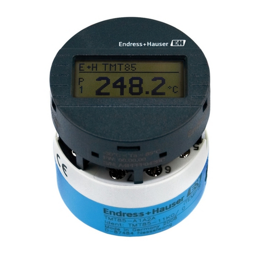
Endress+Hauser iTEMP TMT85 Operating Instructions Manual
Dual-input temperature transmitter with foundation fieldbus protocol
Hide thumbs
Also See for iTEMP TMT85:
- Operating instructions manual (86 pages) ,
- Brief operating instructions (68 pages) ,
- Manual (21 pages)

Related Manuals for Endress+Hauser iTEMP TMT85


Summary of Contents for Endress+Hauser iTEMP TMT85
- Page 1 Products Solutions Services BA00251R/09/EN/16.20 71498847 2020-06-18 Valid as of version 01.02 (device version) Operating Instructions iTEMP TMT85 Dual-input temperature transmitter with FOUNDATION Fieldbus protocol...
-
Page 3: Table Of Contents
TMT85 Table of contents Table of contents About this document ....4 Diagnostics and troubleshooting . . . 37 Document function ..... -
Page 4: About This Document
About this document iTEMP TMT85 About this document Document function These Operating Instructions contain all the information that is required in various phases of the life cycle of the device: from product identification, incoming acceptance and storage, to mounting, connection, operation and commissioning through to troubleshooting, maintenance and disposal. - Page 5 TMT85 About this document Symbol Meaning Ground connection A grounded terminal which, as far as the operator is concerned, is grounded via a grounding system. Protective Earth (PE) A terminal which must be connected to ground prior to establishing any other connections.
-
Page 6: Tool Symbols
The Brief Operating Instructions contain all the essential information from incoming acceptance to initial commissioning. The document types listed are available: In the Download Area of the Endress+Hauser website: www.endress.com → Download Registered trademarks FOUNDATION Fieldbus Registered trademark of the Fieldbus Foundation, Austin, Texas, USA... -
Page 7: Basic Safety Instructions
TMT85 Basic safety instructions Basic safety instructions Requirements for personnel The personnel for installation, commissioning, diagnostics and maintenance must fulfill the following requirements: ‣ Trained, qualified specialists: must have a relevant qualification for this specific function and task ‣... -
Page 8: Product Safety
It meets general safety standards and legal requirements. It also complies with the EC directives listed in the device-specific EC Declaration of Conformity. Endress+Hauser confirms this by affixing the CE mark to the device. -
Page 9: Incoming Acceptance And Product
(www.endress.com/deviceviewer): All data relating to the device and an overview of the Technical Documentation supplied with the device are displayed. • Enter the serial number on the nameplate into the Endress+Hauser Operations App or scan the 2-D matrix code (QR code) on the nameplate with the Endress+Hauser Operations App: all the information about the device and the technical documentation pertaining to the device is displayed. -
Page 10: Scope Of Delivery
Incoming acceptance and product identification iTEMP TMT85 3.2.2 Name and address of manufacturer Name of manufacturer: Endress+Hauser Wetzer GmbH + Co. KG Address of manufacturer: Obere Wank 1, D-87484 Nesselwang or www.endress.com Address of manufacturing plant: See nameplate Scope of delivery The scope of delivery of the device comprises: •... -
Page 11: Installation
TMT85 Installation Installation Installation conditions 4.1.1 Dimensions The dimensions of the device are provided in the "Technical data" section .→ 50 4.1.2 Mounting location • In the terminal head, flat face, as per DIN EN 50446, direct mounting on insert with cable entry (middle hole 7 mm) •... - Page 12 Installation iTEMP TMT85 4.2.1 Mounting the head transmitter Item A Item B . 7 2 i n ) Item C . 7 2 i n ) A0039675-EN 2 Head transmitter mounting (three versions) Item A Mounting in a terminal head (terminal head flat face as per DIN 43729)
- Page 13 TMT85 Installation Item B Mounting in a field housing Field housing cover Mounting screws with springs Head transmitter Field housing 21 mm (0.83 in) . 7 2 i n ) 6.5 mm (0.25 in) . 5 1 i n ) A0024604 ...
- Page 14 Installation iTEMP TMT85 Mounting typical of North America A0008520 4 Head transmitter mounting Thermowell Insert Adapter, coupling Terminal head Head transmitter Mounting screws Thermometer design with thermocouples or RTD sensors and head transmitter: 1. Fit the thermowell (1) on the process pipe or the container wall. Secure the thermowell according to the instructions before the process pressure is applied.
-
Page 15: Post-Installation Check
After mounting, securely tighten the terminal head cover. The display can be used only with the appropriate terminal heads - cover with viewing window (e.g. TA30 from Endress+Hauser). Post-installation check After installing the device, always run the following final checks:... -
Page 16: Electrical Connection
When connecting Ex-certified devices, please take special note of the instructions and connection schematics in the Ex-specific supplement to these Operating Instructions. Please contact Endress+Hauser' s representative if you have any questions. ‣ Do not occupy the display connection. Connecting other devices can destroy the electronics. - Page 17 TMT85 Electrical connection 5.2.1 Connecting the sensor cables Terminal assignment of the sensor connections → 6, 16. NOTICE When connecting 2 sensors ensure that there is no galvanic connection between the sensors (e.g. caused by sensor elements that are not isolated from the thermowell).
- Page 18 Electrical connection iTEMP TMT85 Item B, fine-strand wire without ferrule: 1. Strip wire end. Min. stripping length 10 mm (0.39 in). 2. Press down on the lever opener. 3. Insert the wire end into the terminal. 4. Release lever opener.
- Page 19 TMT85 Electrical connection Maximum overall cable length The maximum network expansion depends on the type of protection and the cable specifications. The overall cable length combines the length of the main cable and the length of all spurs (>1 m/3.28 ft). Please note the following: •...
- Page 20 Electrical connection iTEMP TMT85 • Using a conventional cable gland → 20 • Using the fieldbus connector (optional, available as an accessory) → 20 Risk of damage • Switch off the power supply before installing or connecting the head transmitter.
- Page 21 TMT85 Electrical connection This connection technology using prefabricated distribution modules and plug-in connectors offers substantial advantages over conventional wiring: • Field devices can be removed, replaced or added at any time during normal operation. Communication is not interrupted. • Installation and maintenance are significantly easier.
-
Page 22: Ensuring The Degree Of Protection
Electrical connection iTEMP TMT85 Ensuring the degree of protection The measuring system meets all the requirements of IP67 protection. Compliance with the following points is mandatory following installation in the field or servicing in order to ensure that IP67 protection is maintained: •... - Page 23 TMT85 Electrical connection Device condition and specifications Notes Has the max. length of the fieldbus cable been → 18 observed in accordance with the fieldbus specifications? Has the max. length of the spurs been observed in accordance with the fieldbus specifications?
-
Page 24: Operation Options
Operation options iTEMP TMT85 Operation options Overview of operation options Operators have a number of options for configuring and commissioning the device: 1. Configuration programs FF functions and device-specific parameters are configured via the fieldbus interface. Special configuration and operating programs are available from various manufacturers for this purpose. -
Page 25: Measured Value Display And Operating Elements
TMT85 Operation options Measured value display and operating elements 6.2.1 Display elements Head transmitter A0008549 12 Optional LC display for head transmitter Item no. Function Description Displays the TAG TAG, 32 characters long. ' C ommunication' symbol The communication symbol appears when read and write-accessing via the fieldbus protocol. - Page 26 Operation options iTEMP TMT85 NOTICE ‣ ESD - electrostatic discharge. Protect the terminals from electrostatic discharge. Failure to observe this may result in the destruction or malfunction of parts of the electronics. 1: Connection to head transmitter 2: DIP switches (1 - 64, SW/HW, ADDR and SIM = simulation mode) no function for this head transmitter 3: DIP switch (WRITE LOCK = write protection;...
-
Page 27: System Integration
TMT85 System integration System integration FOUNDATION Fieldbus technology The FOUNDATION Fieldbus (FF) is a purely digital, serial communication system that connects fieldbus devices (sensors, actuators), automation and process control systems with each other. As a local communications network (LAN) for field devices, the FF was primarily designed for the requirements of process engineering. - Page 28 System integration iTEMP TMT85 • All fieldbus devices are powered via the H1 bus. Like the fieldbus devices, the power supply unit is connected in parallel to the bus line. Devices requiring external power must use a separate power supply.
- Page 29 TMT85 System integration 7.1.4 Device ID, addressing Each fieldbus device in the FF network is identified by a unique device ID (DEVICE_ID). The fieldbus host system (LAS) automatically gives the network address to the field device. The network address is the address that the fieldbus currently uses.
-
Page 30: Configuration Of The Measuring Device And Ff Functions
System integration iTEMP TMT85 • Free via the Internet: www.endress.com • Via the Fieldbus FOUNDATION Organization: www.fieldbus.org Configuration of the measuring device and FF functions The FF communication system will only function properly if correctly configured. You can obtain special configuration and operating programs from various manufacturers for the configuration. -
Page 31: Commissioning
TMT85 Commissioning Commissioning Installation check Before commissioning the measuring point make sure that all final checks have been carried out: • "Post-installation check" checklist, → 15 • "Post-connection check” checklist, → 16 Compliance with the function-specific data of the FOUNDATION Fieldbus interface according to IEC 61158-2 (MBP) is mandatory. - Page 32 Commissioning iTEMP TMT85 • The files required for commissioning and network configuration can be obtained as described on → 27. • In the case of the FOUNDATION Fieldbus , the device is identified in the host or configuration system by means of the device ID (DEVICE_ID). The DEVICE_ID is a combination of the manufacturer ID, device type and device serial number.
- Page 33 TMT85 Commissioning 8.3.1 Initial commissioning The following description takes you step-by-step through the device commissioning process and all the necessary configurations for the FOUNDATION Fieldbus 1. Open the configuration program. 2. Load the device description files or the CFF file into the host system or the configuration program.
- Page 34 Commissioning iTEMP TMT85 A0042921 15 Screen displayed in the "NI-FBUS Configurator" configuration program (National Instruments) once the connection is established Device designation in the Configurator (EH_TMT85_xxxxxxxxxxx = tag name PD_TAG) and block structure Configuring the “Resource Block” (base index 400) 6.
- Page 35 TMT85 Commissioning 12. Open Analog Input function block 1. 13. Set the operating mode in the MODE_BLK parameter group (TARGET parameter) to OOS, i.e. the block is out of service. 14. Use the parameter to select the process variable which should be used as the input value for the function block algorithm (scaling and limit value monitoring functions).
- Page 36 Commissioning iTEMP TMT85 System configuration / connecting function blocks: A0042922 A final "overall system configuration" is necessary so that the operating mode of the Analog Input function block can be set to AUTO and the field device is integrated into the system application.
-
Page 37: Diagnostics And Troubleshooting
TMT85 Diagnostics and troubleshooting Diagnostics and troubleshooting Troubleshooting Always start troubleshooting with the checklists below if faults occur after start up or during operation. This takes you directly (via various queries) to the cause of the problem and the appropriate remedial measures. - Page 38 Diagnostics and troubleshooting iTEMP TMT85 Problems when configuring function blocks Transducer Blocks: Check whether the operating mode of the Resource Block is set to AUTO → The operating mode MODE_BLK parameter group / TARGET parameter. cannot be set to AUTO.
-
Page 39: Status Messages
TMT85 Diagnostics and troubleshooting Status messages The device displays warnings or alarms as status messages. If errors occur during commissioning or measuring operation, these errors are displayed immediately. Errors are displayed in the configuration program via the parameter in the Physical Block or on the attached display. - Page 40 Diagnostics and troubleshooting iTEMP TMT85 9.2.1 Category F diagnostics messages Category Status messages Error messages in the Sensor Cause of error / Output variables relevant Sensor Transducer Block remedy affected • ACTUAL_STAT Transducer Block measured value US_NUMBER status (default) in the...
- Page 41 TMT85 Diagnostics and troubleshooting Category Status messages Error messages in the Sensor Cause of error / Output variables relevant Sensor Transducer Block remedy affected • ACTUAL_STAT Transducer Block measured value US_NUMBER status (default) in the 'Advanced Diagnostics' Transducer Block •...
- Page 42 Diagnostics and troubleshooting iTEMP TMT85 Category Status messages Error messages in the Sensor Cause of error / Output variables relevant Sensor Transducer Block remedy affected • ACTUAL_STAT Transducer Block measured value US_NUMBER status (default) in the 'Advanced Diagnostics' Transducer Block •...
- Page 43 TMT85 Diagnostics and troubleshooting Category Status messages Error messages in the Sensor Cause of error / Output variables relevant Sensor Transducer Block remedy affected • ACTUAL_STAT Transducer Block measured value US_NUMBER status (default) in the 'Advanced Diagnostics' Transducer Block •...
-
Page 44: Application Errors Without Messages
Diagnostics and troubleshooting iTEMP TMT85 • Off (Diagnostic event 041 sensor break (default category: F) is output when the alarm limit is reached) • On (Diagnostic event 042 sensor corrosion (default category: M) is output before the alarm limit is reached. This allows preventative maintenance/troubleshooting to be performed. -
Page 45: Spare Parts
TMT85 Diagnostics and troubleshooting Symptoms Cause Action/remedy Sensor, sensing element Check the sensor, sensing element defective RTD connection incorrect Connect the connecting cables correctly (see the "Electrical connection" section ) Programming Incorrect sensor type set in the SENSOR_TYPE device function. Set the correct sensor type... -
Page 46: Return
Maintenance iTEMP TMT85 Return The requirements for safe device return can vary depending on the device type and national legislation. 1. For more information, please refer to our website: https://www.endress.com/en/instrumentation-services/instrumentation-repair 2. Return the device if repairs or a factory calibration are required, or if the wrong device was ordered or delivered. -
Page 47: Return
Various accessories, which can be ordered with the device or subsequently from Endress +Hauser, are available for the device. Detailed information on the order code in question is available from your local Endress+Hauser sales center or on the product page of the Endress+Hauser website: www.endress.com. -
Page 48: Communication-Specific Accessories
DeviceCare is the tool developed by Endress+Hauser for the configuration of Endress+Hauser devices. All smart devices in a plant can be configured via a point- to-point or point-to-bus connection. The user-friendly menus enable transparent and intuitive access to the field devices. - Page 49 The application already contains the data of your Endress+Hauser device. Endress+Hauser also takes care of maintaining and updating the data records. W@M is available: Via the Internet: www.endress.com/lifecyclemanagement...
-
Page 50: Technical Data
Technical data iTEMP TMT85 Technical data 13.1 Input Measured variable Temperature (temperature-linear transmission behavior), resistance and voltage. Measuring range Two independent sensors can be connected. The measuring inputs are not galvanically isolated from each other. Resistance thermometer Designation α Measuring range limits... -
Page 51: Output
TMT85 Technical data Thermocouples as Designation Measuring range limits per standard • 2-wire connection • Internal reference junction (Pt100) • External preset value: configurable value –40 to +85 °C (–40 to +185 °F) • Maximum sensor wire resistance 10 kΩ (If the sensor wire resistance is greater than 10 kΩ, an error message is output in accordance with NAMUR NE89.) - Page 52 Technical data iTEMP TMT85 Current consumption ≤ 11 mA Switch-on delay Basic data FOUNDATION Fieldbus basic data Device type 10CE (hex) Device revision Node address Default: 247 ITK version 6.0.1 ITK Certification Driver No. IT085900 Link Master capability (LAS) Choice of Link Master / Basic Device Yes;...
-
Page 53: Power Supply
TMT85 Technical data Brief description of the Resource Block blocks The Resource Block contains all the data that clearly identify and characterize the device. It is like an electronic version of the device nameplate. In addition to parameters required to operate the device on the fieldbus, the Resource Block makes information available such as the order code, device ID, hardware version, firmware version, etc. -
Page 54: Performance Characteristics
Technical data iTEMP TMT85 Terminals Choice of screw or spring terminals for sensor and supply cables: Terminal version Cable version Cable cross-section Screw terminals(with tabs on the fieldbus terminals for easy Rigid or flexible ≤ 2.5 mm² (14 AWG) connection of a handheld terminal, e.g. - Page 55 TMT85 Technical data Standard Designation Measuring range Measured error (±) Non-repeatability (±) –200 to +250 °C 0.05 °C (0.09 °F) + 0.015% * (MV Pt500 (3) ≤ 0.16 °C (0.29 °F) ≤ 0.08 °C (0.14 °F) (–328 to +482 °F) - LRV) –200 to +250 °C...
- Page 56 Technical data iTEMP TMT85 Non- Standard Designation Measuring range Measured error (±) repeatabil ity (±) 0.36 °C (0.47 °F) - 0.04% * ≤ 0.11 °C Type T (40) –150 to +400 °C (–238 to +752 °F) ≤ 0.36 °C (0.47 °F) (MV - LRV) (0.20 °F)
- Page 57 TMT85 Technical data • Callendar-Van Dusen coefficients (Pt100 resistance thermometer) The Callendar-Van-Dusen equation is described as: R T = R 0 [1+AT+BT²+C(T-100)T³] The coefficients A, B and C are used to match the sensor (platinum) and transmitter in order to improve the accuracy of the measuring system. The coefficients for a standard sensor are specified in IEC 751.
- Page 58 Technical data iTEMP TMT85 Ambient temperature: Supply voltage: Designation Standard Influence (±) per 1 °C (1.8 °F) change Influence (±) per V change 0.0015% * (MV -LRV), 0.0015% * (MV -LRV), 10 to 400 Ω ≤ 6 mΩ ≤ 6 mΩ...
- Page 59 TMT85 Technical data Total measured error of transmitter at current output = √(Measured error digital² + Measured error D/A²) Long-term drift, resistance thermometers (RTD) and resistance transmitters Designation Standard Long-term drift (±) after 1 year after 3 years after 5 years Maximum ≤...
-
Page 60: Environment
Technical data iTEMP TMT85 Designation Standard Long-term drift (±) ≤ 0.09 °C (0.162 °F) + 0.017% * ≤ 0.14 °C (0.252 °F) + 0.023% * ≤ 0.19 °C (0.342 °F) + 0.024% * Type K (36) (MV + 150 °C (270 °F)) -
Page 61: Mechanical Construction
TMT85 Technical data Electromagnetic compatibility in accordance with all the relevant requirements of the IEC/EN 61326 series and NAMUR Recommendation EMC (NE21). For details, refer to the Declaration of Conformity. Maximum measured error <1% of measuring range. Interference immunity as per IEC/EN 61326 series, industrial requirements... - Page 62 Technical data iTEMP TMT85 Field housing All field housings have an internal geometry in accordance with DIN EN 50446, form B (flat face). Cable glands in the diagrams: M20x1.5 Maximum ambient temperatures for cable glands Type Temperature range Polyamide cable gland ½" NPT, M20x1.5 (non-Ex) –40 to +100 °C (–40 to 212 °F)
- Page 63 TMT85 Technical data TA30H Specification • Flameproof (XP) version, explosion-protected, captive screw 125 (4.92) cap, with two cable entries • Protection class: NEMA Type 4x Encl. • Temperature: –50 to +150 °C (–58 to +302 °F) for rubber seal without cable gland (observe max.
-
Page 64: Certificates And Approvals
Technical data iTEMP TMT85 TA30D Specification • 2 cable entries 107.5 (4.23) • Temperature: –50 to +150 °C (–58 to +302 °F) without cable gland • Material: aluminum, polyester powder coated Seals: silicone • Cable entry glands: 1/2" NPT and M20x1.5 •... -
Page 65: Supplementary Documentation
TMT85 Technical data CSA GP CSA General Purpose The temperature transmitter is certified and registered by the Fieldbus FOUNDATION. The FOUNDATION Fieldbus device meets all the requirements of the following specifications: certification • Certified in accordance with FOUNDATION Fieldbus specification •... -
Page 66: Operation Via Foundation Fieldbus Tm
TMT85 Operation via FOUNDATION Fieldbus Operation via FOUNDATION Fieldbus 14.1 Block model With FOUNDATION Fieldbus , all the device parameters are categorized according to their functional properties and task and are generally assigned to three different blocks. A block can be regarded as a container that contains parameters and the functionalities associated with these parameters. - Page 67 TMT85 Operation via FOUNDATION Fieldbus 14.2.1 Selecting the operating mode The operating mode is set via the MODE_BLK parameter group. The Resource Block supports the following operating modes: • AUTO (automatic mode) • OOS (out of service) • MAN (manual mode) The ' O ut Of Service' (OOS) mode is also shown via the BLOCK_ERR parameter.
- Page 68 TMT85 Operation via FOUNDATION Fieldbus alarm priority specifies the action taken when the write protection alarm WRITE_ALM is active. If the option of a process alarm has not been activated in the ACK_OPTION parameter, this process alarm only has to be acknowledged in the BLOCK_ALM parameter.
- Page 69 TMT85 Operation via FOUNDATION Fieldbus Resource Block Parameter Parameter Write access with Description Index operating mode (MODE_BLK) Confirm Time AUTO - OOS Specify the confirmation time for the event report. If the device does not (CONFIRM_TIME) receive confirmation within this time, the event report is sent to the fieldbus host system again.
- Page 70 TMT85 Operation via FOUNDATION Fieldbus Resource Block Parameter Parameter Write access with Description Index operating mode (MODE_BLK) Maintenance Mask AUTO - OOS Disables the transmission of device messages to the fieldbus. (FD_MAINT_MASK) Maintenance Priority AUTO - OOS Indicates the alarm priority of the alarm transmitted to the fieldbus.
- Page 71 Manufacturer ID Read only Displays the manufacturer' s ID number. (MANUFAC_ID) Display: 0x452B48 (hex) = Endress+Hauser Max Notify (MAX_NOTIFY) Read only Displays the maximum number of event reports supported by the device that can simultaneously exist as unconfirmed reports. Display:...
- Page 72 TMT85 Operation via FOUNDATION Fieldbus Resource Block Parameter Parameter Write access with Description Index operating mode (MODE_BLK) Restart (RESTART) AUTO - OOS The device can be reset in a variety of ways via this parameter. Options: • Restart UNINITIALIZED •...
-
Page 73: Transducer Blocks
TMT85 Operation via FOUNDATION Fieldbus Resource Block Parameter Parameter Write access with Description Index operating mode (MODE_BLK) Update Event (UPDATE_EVT) Read only Indicates whether static block data have been modified, including the date and time. Write Alarm (WRITE_ALM) AUTO - OOS Displays the status of the write protection alarm. - Page 74 TMT85 Operation via FOUNDATION Fieldbus used to specify which process variable is read in and processed in the downstream Analog Input function block. Block Process variable Channel parameter (AI Block) Channel Transducer Block “Sensor 1” Primary Value Primary Value 1...
- Page 75 TMT85 Operation via FOUNDATION Fieldbus 14.3.6 FF parameters of the Transducer Blocks The following table provides a description of all the specified FOUNDATION Fieldbus parameters of the Transducer Blocks. The device-specific parameters are described from → 80. Transducer Block (FF parameters)
- Page 76 TMT85 Operation via FOUNDATION Fieldbus Parameter Write access Description with operating mode (MODE_BLK) Block Error Read only Displays the active block errors. (BLOCK_ERR) Display: OUT OF SERVICE The block is in the “Out of Service” mode. The following block errors are only displayed in the Sensor Transducer Blocks: •...
- Page 77 TMT85 Operation via FOUNDATION Fieldbus 14.3.7 Transducer Blocks "Sensor 1 and 2" The "Sensor 1 and 2" Transducer Blocks evaluate the signals of both sensors from a metrological perspective and display them as a physical variable (value, measured value status and unit).
- Page 78 TMT85 Operation via FOUNDATION Fieldbus The units displayed are selected with the PRIMARY_VALUE_UNIT and SENSOR_ RANGE → UNITS_INDEX parameters. It must be ensured that the selected units physically suit the measured variables. The Sensor 1 and 2 Transducer Blocks each provide the "Quick Setup" wizard for the quick and safe configuration of the measurement settings.
- Page 79 TMT85 Operation via FOUNDATION Fieldbus A0042927 21 Linear scaling of temperature-linear curve Linearization of platinum resistance thermometers using Callendar Van Dusen coefficients: The coefficients R0, A, B, C can be specified in the CVD_COEFF_R0, CVD_COEFF_A, CVD_COEFF__B, CVD_COEFF_C parameters. To activate this linearization, select the "RTD Callendar Van Dusen"...
- Page 80 TMT85 Operation via FOUNDATION Fieldbus Display Description PV type calculation mode and "No Sensor" The PV is an interconnection of the two sensor inputs, but "No chosen Sensor" is selected as the sensor type. PV type calculation mode, sensor 1 unit The PV is an interconnection of the two sensor inputs;...
- Page 81 TMT85 Operation via FOUNDATION Fieldbus Parameter Write access Description with operating mode (MODE_BLK) Primary value type Displays the calculation process for the PRIMARY_VALUE. (PRIMARY_VALUE_TYPE) Display: Sensor Transducer 1: • PV = SV_1: Sensor value 1 • PV = SV_1-SV_2: Difference •...
- Page 82 TMT85 Operation via FOUNDATION Fieldbus Parameter Write access Description with operating mode (MODE_BLK) Sensor range (SENSOR_ Read only Physical measuring range of the sensor: RANGE) (EU_100, EU_0) EU_100 (upper sensor range limit) EU_0 (lower sensor range limit) (UNITS_INDEX, UNITS_INDEX (unit of the SENSOR_VALUE)
- Page 83 TMT85 Operation via FOUNDATION Fieldbus Parameter Write access Description with operating mode (MODE_BLK) Callendar Van Dusen A Sensor linearization according to the Callendar Van Dusen (CVD_COEFF_A) method. The CVD_COEFF_XX parameters are used to Callendar Van Dusen B calculate the sensor characteristic curve if "RTD- (CVD_COEFF_B) Callendar Van Dusen"...
- Page 84 TMT85 Operation via FOUNDATION Fieldbus 14.3.8 Transducer Block "Advanced Diagnostic" The "Advanced Diagnostic" Transducer Block is used to configure and display all the diagnostic functions of the transmitter. Functions such as • Corrosion detection • Drift detection • Ambient temperature monitoring are displayed here.
- Page 85 TMT85 Operation via FOUNDATION Fieldbus In addition, the entire status information of the device and the maximum/minimum indicators for the two sensor values and the internal temperature are also available. Transducer Block “ADVANCED DIAGNOSTIC” (device-specific parameters) Parameter Write access...
- Page 86 TMT85 Operation via FOUNDATION Fieldbus Parameter Write access Description with operating mode (MODE_BLK) Actual Status Number / Read only / Current/previous status number: Previous Status Number AUTO - OOS 000 NO_ERROR: No error is present (ACTUAL_ STATUS_ 041 SENSOR_BREAK: Sensor break...
- Page 87 TMT85 Operation via FOUNDATION Fieldbus Parameter Write access Description with operating mode (MODE_BLK) Sensor 2 Min. Indicator AUTO - OOS Indicator for the minimum value to occur at sensor 2, can be SV2_MIN_ INDICATOR reset by writing any value in this parameter.
- Page 88 TMT85 Operation via FOUNDATION Fieldbus Parameter Write access with Description operating mode (MODE_BLK) Display source x AUTO - OOS Use this function to select the value to be displayed. Possible DISP_SOURCE_X settings: • Off • Primary Value 1 • Sensor Value 1 •...
-
Page 89: Analog Input Function Block
TMT85 Operation via FOUNDATION Fieldbus The following settings should therefore be made in the "Display" Transducer Block: Parameter Value DISP_SOURCE_1 ' P rimary Value 1' DISP_VALUE_1_DESC TEMP PIPE 11 DISPLAY_VALUE_1_FORMAT ' x xx.xx' DISP_SOURCE_2 ' D EVTEMP_VALUE' DISP_VALUE_2_DESC INTERN TEMP DISPLAY_VALUE_2_FORMAT ' x xxx.x'... - Page 90 TMT85 Operation via FOUNDATION Fieldbus • The diagnostic category as per NAMUR Recommendation NE107 is transmitted over the fieldbus in a format that is independent of the manufacturer: • F: Failure • C: Function check • S: Out of specification •...
- Page 91 TMT85 Operation via FOUNDATION Fieldbus Event weighting Default event category Event source Bit Events in this group Lowest weighting Maintenance required (M) Sensor • M042: Sensor corrosion • M101: Sensor value too low • M102: Sensor value too high •...
- Page 92 TMT85 Operation via FOUNDATION Fieldbus Proceed as follows to change the diagnostic behavior of an event group: 1. Open the assignment parameter in which the group is currently assigned. 2. Change the event group bit from 1 to 0. In the configuration systems, this is done by deselecting the corresponding check box.
- Page 93 TMT85 Operation via FOUNDATION Fieldbus A0042930 It is important to ensure that the corresponding bit is set in at least one of the assignment parameters for each event group. Otherwise no category will be transmitted with the event over the bus, and the control system will therefore generally ignore the presence of the event.
-
Page 94: Bus
TMT85 Operation via FOUNDATION Fieldbus A0042931 Select one of these bits (here for example: Configurable Area Bit 1) and select the Drift option from the corresponding selection list. Press Enter to confirm the option selected. A0042932 Now go to the Resource Block and activate the corresponding bit (here: Configurable Area Bit 1) in the FD_OFFSPEC_MAP parameter. - Page 95 TMT85 Operation via FOUNDATION Fieldbus 14.8.1 Event priority Event messages are only transmitted over the bus if their priority is between 2 and 15. Priority 1-events are displayed but are not transmitted over the bus. Priority 0-events are ignored. In the factory setting, the priority of all events is 0. The priority can be individually changed for the four assignment parameters.
-
Page 96: Index
Index iTEMP TMT85 Index Accessories Communication-specific ....48 Device-specific ......47 Cable type . - Page 100 *71498847* 71498847 www.addresses.endress.com...