
Related Manuals for Extreme Networks ExtremeWireless AP460i


Summary of Contents for Extreme Networks ExtremeWireless AP460i
- Page 1 ExtremeWireless™ AP460i/e Access Points Installation Guide 9036418-01 Rev AA October 2020...
- Page 2 Copyright © 2020 Extreme Networks, Inc. All rights reserved. Legal Notice Extreme Networks, Inc. reserves the right to make changes in specifications and other information contained in this document and its website without prior notice. The reader should in all cases consult representatives of Extreme Networks to determine whether any such changes have been made.
-
Page 3: Table Of Contents
Table of Contents Preface......................................v Conventions..................................v Text Conventions..............................v Providing Feedback to Us............................vi Getting Help................................... vi Subscribing to Service Notifications......................vii Documentation and Training..........................vii Training................................... vii AP460i/e Overview......................8 AP460i/e Features..............................8 Power Source................................. 11 AP460i/e Power Tables............................11 LED Indicators................................11 Access Point Purchase Order Information..................... - Page 4 Table of Contents Cable Gland Adapter Assembly......................... 38 Safe Removal of the RJ45 Cable..................43 Antenna Configuration for External Antenna Model Access Point......44 Form a Drip Loop Connection for Cables..............46 Access Points Specifications................... 47 Product specifications.............................47 Environmental specifications..........................47 Regulatory and Compliance Information...............48 Professional Installation Instruction........................48 Qualified personnel............................
-
Page 5: Preface
Preface This section describes the text conventions used in this document, where you can find additional information, and how you can provide feedback to us. Conventions This section discusses the conventions used in this guide. Text Conventions The following tables list text conventions that are used throughout this guide. Table 1: Notice Icons Icon Notice Type... -
Page 6: Providing Feedback To Us
Italics are also used when referring to publication titles. Providing Feedback to Us Quality is our first concern at Extreme Networks, and we have made every effort to ensure the accuracy and completeness of this document. We are always striving to improve our documentation and help... -
Page 7: Subscribing To Service Notifications
Hardware/Software Compatibility Matrices https://www.extremenetworks.com/support/compatibility-matrices/ White papers, data sheets, case studies, https://www.extremenetworks.com/resources/ and other product resources Training Extreme Networks offers product training courses, both online and in person, as well as specialized certifications. For more information, visit www.extremenetworks.com/education/. ExtremeWireless™ AP460i/e Access Points... -
Page 8: Ap460I/E Overview
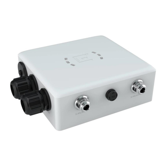
AP460i/e Overview AP460i/e Features on page 8 Power Source on page 11 AP460i/e Power Tables on page 11 LED Indicators on page 11 Access Point Purchase Order Information on page 13 The AP460i/e access points are outdoor model enterprise class 802.11ax access points. The “i” in AP460i indicates that the access point comes with internal antennas and the “e”... - Page 9 AP460i/e Overview AP460i/e Features • Antennas: ◦ Eight WiFi internal/external antennas ◦ One BLE internal antenna on AP460i ◦ One BLE external antenna port on AP460e • Temperature: -40°C to +60°C (-40°F to +140°F) @ 6000 ft. • Enclosure: Plastic with metal base Figure 1: AP460i access point front view Callout Description...
- Page 10 AP460i/e Features AP460i/e Overview Figure 2: AP460e access point front view Callout Description Console port and reset button cap GE1-PoE Vent Note On the AP460e access point, the sensor and the BLE antennas come with dust caps on them. Do not remove the dust cap until you need to install the antennas. For information on the AP460e antenna connectors, see antenna configuration for external antenna model access...
-
Page 11: Power Source
AP460i/e Overview Power Source Power Source The AP460i and AP460e access points have one Power over Ethernet (PoE) PD converter that supplies main power to all the downstream. Power source Description Power is provided through the RJ45 Ethernet ports of AP460i/e, compliant to be powered with 802.3at and 802.3bt to provide full functionality. - Page 12 LED Indicators AP460i/e Overview Figure 3: AP460i/e LED indicators Note The LED icons and the status on AP460i and AP460e are the same. Table 5: AP460i/e LED status indicators LED icon LED color Description Status Amber Non-operational status Green Normal operational status Amber 100Mbps Green...
-
Page 13: Access Point Purchase Order Information
AP460i/e Overview Access Point Purchase Order Information Access Point Purchase Order Information The AP460i and AP460e access points must be ordered separately, the ordering details of which are presented in the following tables: Table 6: AP460i purchase order information Part number Description AP460i-FCC Dual and tri-radio 802.11ax/ac/abgn, 4x4:4 MIMO... -
Page 14: Install The Access Point
Verify the box contents. 2. Visually inspect the access point, the bracket, and any other optional accessories you have ordered for physical damage. If there is any damage, contact Extreme Networks Support. 3. Read and review the safety guidelines. 4. Install the ground connection. -
Page 15: Access Point Mounting Options And Bracket Information
Install the Access Point Access Point Mounting Options and Bracket Information Access Point Mounting Options and Bracket Information The access points can be mounted on a wall or to a pole by purchasing separate mounting brackets, which are described in the following table: Table 8: Mounting bracket usage Mounting bracket and Wall install... -
Page 16: Position The Access Point Before Installation
Position the Access Point before Installation Install the Access Point Table 8: Mounting bracket usage (continued) Mounting bracket and Wall install Pole install Notes part number WS-MBO-POLE01 Yes. The POLE01 bracket If the pole diameter is bracket can only be used with >= 1.0 in. -
Page 17: Ground Connection
Install the Access Point Ground Connection Ground Connection About This Task The ground connection for the access point is located on the rear of the device. Attach a ground to earth cable to the grounding terminal. Hardware requirements: • One ground screw •... - Page 18 Ground Connection Install the Access Point 2. Attach the ground wire ring terminal to the access point using the M4 ground screw assembly with the star washer. Note The wire should be as close to the access point bottom as possible. Note The star washer must be in contact with both the ring terminal and the access point.
-
Page 19: Install The Access Point On A Wall Or To A Flat Surface
Install the Access Point Install the Access Point on a Wall or to a Flat Surface Install the Access Point on a Wall or to a Flat Surface You can install the access point on a flat surface such as a wall using one of the following bracket options: •... -
Page 20: Install The Access Point To A Flat Surface Using The Kt-147407-02 Flat Part, 1-Axis Tilt Part, And The Kt- 150173-01 Extension Arm
Install the Access Point to a Flat Surface Using the KT-147407-02 Flat Part, 1-axis Tilt Part, and the KT- 150173-01 Extension Arm Install the Access Point Figure 6: KT-147407-02 bracket 1-axis tilt part Note The flat part and the 1-axis tilt part can be used interchangeably with the access points. You can either attach the flat part or the 1-axis tilt part first, and the rest of the installation procedure will not be affected by it. - Page 21 Install the Access Point to a Flat Surface Using the KT-147407-02 Flat Part, 1-axis Tilt Part, and the KT- Install the Access Point 150173-01 Extension Arm Figure 7: KT-150173-01 extension arm The following hardware is required for installation: • KT-147407-02 flat part •...
-
Page 22: Install The Access Point On A Flat Surface Using The Kt-150173-01 Extension Arm
Install the Access Point On a Flat Surface Using the KT-150173-01 Extension Arm Install the Access Point 5. Using four M6 hex-head screws, attach the KT-150173-01 extension arm to a flat surface. The best practice is to use screw-in anchors with the M6 screws on a wood surface, and concrete anchors on a concrete surface. - Page 23 Install the Access Point on a Flat Surface Using the Install the Access Point MBO-ART02 Articulating Mounting Bracket • Two M6 hex-head screws is used for attaching the MBO-ART02 articulating mounting bracket to the access point • Four M4 hex-head screws are used for attaching the MBO-ART02 articulating mounting bracket to the wall Note The MBO-ART02 bracket has +80 degrees to –80 degrees of articulation on each axis.
-
Page 24: Install The Access Point On A Hard Vehicle Surface Using The Ws-Mbv-Vmm Vehicle Bracket (#32216)
Install the Access Point on a Hard Vehicle Surface Using the WS-MBV-VMM Vehicle Bracket (#32216) Install the Access Point 3. Align the MBO-ART02 articulating mounting bracket holes against the wall attachment holes and attach the bracket using four M4 hex-head screws. Install the Access Point on a Hard Vehicle Surface Using the WS-MBV-VMM Vehicle Bracket (#32216) About This Task... - Page 25 Install the Access Point on a Hard Vehicle Surface Using Install the Access Point the WS-MBV-VMM Vehicle Bracket (#32216) Procedure 1. Using the vehicle assembly plate four long inner slots as a template, mark and drill the attachment holes on a flat surface. Figure 9: VMM vehicle attach assembly plate Callout Description...
- Page 26 Install the Access Point on a Hard Vehicle Surface Using the WS-MBV-VMM Vehicle Bracket (#32216) Install the Access Point 3. Align the large holes on the stiffener plates with the large holes on the access point assembly plate, and attach the stiffener plates to the access point attach assembly plate. Figure 10: VMM access point attach assembly plate stiffener 1 and stiffener 2 Callout Description...
-
Page 27: Install The Access Point On A Pole
Install the Access Point Install the Access Point on a Pole Install the Access Point on a Pole You can install the access point on a pole using the following mounting brackets: • KT-147407-02 bracket parts • KT-147407-02 pole part •... -
Page 28: Attach The Access Point To A Pole Using All Three Kt-147407-02 Bracket Parts
Attach the Access Point to a Pole Using All Three KT-147407-02 Bracket Parts Install the Access Point Figure 11: KT-147407-02 pole part Note The pole install options are applicable to both internal and external antenna model outdoor access points. Attach the Access Point to a Pole Using All Three KT-147407-02 Bracket Parts Before You Begin The following hardware is required to mount the access point on to a pole: •... - Page 29 Attach the Access Point to a Pole Using All Three Install the Access Point KT-147407-02 Bracket Parts • KT-147407-02 pole part • Access point • Four M6 hex-head screws • Two hex-head M12 stainless-steel screws and nuts • Two 0.5 in. (12.7 mm) wide stainless-steel cable clamps About This Task To attach the access point to a pole: Procedure...
- Page 30 Attach the Access Point to a Pole Using All Three KT-147407-02 Bracket Parts Install the Access Point Figure 13: Large bracket holes on the pole part of the KT-147407-02 bracket Callout Description Large bracket holes used for attaching the M12 screws on the pole part of the KT-147407-02 bracket 3.
-
Page 31: Attach The Access Point To A Pole Using The Kt-147407-02 Pole Part
Attach the Access Point to a Pole Using the Install the Access Point KT-147407-02 Pole Part 4. Insert the 0.5 in. (12.7 mm) wide stainless-steel cable clamps through the long slots on the sides of pole bracket. Figure 14: Long slots on the pole part of the KT-147407-02 bracket Callout Description Long slots on the sides of the pole part of the KT-1474017-02 bracket. -
Page 32: Attach The Access Point To A Pole Using Kt-147407-02 Pole Part And The Kt-150173-01 Extension Arm
Attach the Access Point to a Pole Using KT-147407-02 Pole Part and the KT-150173-01 Extension Arm Install the Access Point Figure 15: Semi-circular cuts on the pole part of the KT-147407-02 bracket Callout Description Semi-circular cuts on the pole part of the KT-147407-02 bracket, used for attaching the M6 hex-head screws. -
Page 33: Attach The Access Point To A Pole Using The Kt-147407-02 Bracket Parts And The Kt-150173-01 Extension Arm
Attach the Access Point to a Pole Using the KT-147407-02 Bracket Parts and the KT-150173-01 Install the Access Point Extension Arm Procedure 1. Attach one end of the KT-150173-01 extension arm to the access point using two M6 hex-head screws. 2. - Page 34 Attach the Access Point to a Pole Using the KT-147407-02 Bracket Parts and the KT-150173-01 Extension Arm Install the Access Point 2. Align the circular holes on one end of the KT-150173-01 extension arm against the large holes on the 1-axis tilt part.
-
Page 35: Attach The Access Point To A Pole Using Ws-Mbo-Pole01 Bracket And Mbo-Art02 Articulating Mounting Bracket
Attach the Access Point to a Pole Using WS-MBO- POLE01 Bracket and MBO-ART02 Articulating Mounting Install the Access Point Bracket Attach the Access Point to a Pole Using WS-MBO-POLE01 Bracket and MBO-ART02 Articulating Mounting Bracket Before You Begin The following hardware is required: •... - Page 36 Attach the Access Point to a Pole Using WS-MBO- POLE01 Bracket and MBO-ART02 Articulating Mounting Bracket Install the Access Point 2. Attach the WS-MBO-POLE01 bracket to the MBO-ART02 articulating mounting bracket using four M3 screws, nuts, and washers. Figure 17: POLE01 bracket being attached to the ART02 articulating mounting bracket 3.
-
Page 37: Ge And Console Connections
GE and Console Connections Console Cap Assembly on page 37 Cable Gland Adapter Assembly on page 38 The access points have two GE (Ethernet) ports and a Console port. During administration and maintenance through the GE or Console port, the access points must still have a power connection through an Ethernet PoE cable. -
Page 38: Cable Gland Adapter Assembly
Cable Gland Adapter Assembly GE and Console Connections 2. Loop the console port cap tie to the back of the access point, and place it on top of the tether screw hole. Figure 18: Console port cap tie installation 3. Add the Phillips head screw through the console port cap tie and tether screw hole. 4. - Page 39 GE and Console Connections Cable Gland Adapter Assembly Figure 19: RJ45 cable gland adapter assembly Callout Description Sealing nut Claw Seal Main body About This Task Install the cable gland adapter assembler onto the GE1 or GE2 port: ExtremeWireless™ AP460i/e Access Points...
- Page 40 Cable Gland Adapter Assembly GE and Console Connections Procedure 1. Insert the RJ45 cable onto the sealing nut. 2. Slide the claw and seal onto the RJ45 cable. 3. Attach the main body into the GE1 or GE2 port of the access point. ExtremeWireless™...
- Page 41 GE and Console Connections Cable Gland Adapter Assembly 4. Plug the RJ45 cable into the port. Caution Do not run the network cable through the cable conduit connector used for connecting the power cables. You must connect the network cable and power cables through separate connectors.
- Page 42 Cable Gland Adapter Assembly GE and Console Connections 7. Tighten the adapter assembly by hand to 5-in. lbs. Note There should still be some visible threads after you torque in the cap. ExtremeWireless™ AP460i/e Access Points...
-
Page 43: Safe Removal Of The Rj45 Cable
Safe Removal of the RJ45 Cable Procedure 1. Loosen the GE1 gland cap. 2. Move the gland cap, gland cage, and the gland gasket at least 6 in. away from the LAN cable and the gland area. 3. Use a thin, strong, and non-conductive tool like a flat-bladed orange stick to reach into the gland, and press down the plastic locking latch of the RJ45 connector. -
Page 44: Antenna Configuration For External Antenna Model Access Point
Antenna Configuration for External Antenna Model Access Point Figure 20: AP460e external antenna connector ports Antenna socket radio mapping information • Radio 1 (R1) − antennas 5 and 6 • Radio 2 (R2) − antennas 1, 2, 3, and 4 •... - Page 45 Antenna Configuration for External Antenna Model Access Point The 2.4G and 5G–8 and the 2.4G and 5G–7 are sensor antenna ports. Note The internal BLE is always used unless you attach an antenna to the BLE antenna connector. Note The BLE antenna port and the sensor antenna ports come with dust caps installed on them. Do not remove the dust caps until you need to install the antennas.
-
Page 46: Form A Drip Loop Connection For Cables
Form a Drip Loop Connection for Cables After the cables and antennas are connected to the access point, gather each cable below the access point, and form a drip loop connection. You do not need a drip loop if the LAN wire is already below the access point. -
Page 47: Access Points Specifications
Access Points Specifications Product specifications Item Specification Dimensions 10.5in. × 7.5in. × 2.5in. (260.0 mm × 192.0 mm × 65.0 mm) Weight AP460i - 3.7 lbs. (1.7 kg) AP460e - 3.9 lbs. (1.8 kg) Housing IP67 rated for outdoor use LEDs Seven Radios... -
Page 48: Regulatory And Compliance Information
Regulatory and Compliance Information Professional Installation Instruction on page 48 Safety Guidelines on page 49 Federal Communications Commission (FCC) Notice on page 50 Industry Canada Notice on page 50 Detachable Antenna Usage on page 51 Australia Notice on page 52 Brazil Agência Nacional De Telecomunicações (Anatel) Statement on page 52 Hazardous Substances... -
Page 49: Installation Procedure
Regulatory and Compliance Information Installation procedure Installation procedure Refer to the installation instructions for details. Warning Select the installation position and make sure that the final output power does not exceed the limit set forth in relevant rules. The violation of the rule could lead to serious federal penalty. Instructions d'installation professionnelle Personnel d'installation Ce produit est conçu pour une application spécifique et doit être installé... -
Page 50: Federal Communications Commission (Fcc) Notice
Federal Communications Commission (FCC) Notice Regulatory and Compliance Information Federal Communications Commission (FCC) Notice This equipment has been tested and found to comply with the limits for a Class B digital device, pursuant to Part 15 of the FCC Rules. These limits are designed to provide reasonable protection against harmful interference in a residential installation. -
Page 51: Detachable Antenna Usage
Regulatory and Compliance Information Detachable Antenna Usage brouillage préjudiciable, et (2) ce dispositif doit accepter tout brouillage reçu, y compris un brouillage susceptible de provoquer un fonctionnement indésirable. Caution The device for operation in the band 5150-5250 MHz is only for indoor use to reduce the potential for harmful interference to co-channel mobile satellite systems. -
Page 52: Australia Notice
Australia Notice Regulatory and Compliance Information Group Brand Model number Antenna type Antenna gain (dBi) 2.4 GHz 5 GHz BLE or thread Extreme ML-2452- Panel PNA5-01R Extreme ML-2452- Omni PTA4M4-036 Extreme ML-2452- Omni HPAG5A8-01 Extreme WS-AO- Omni DQ04360N Extreme AI-DQ04360S Omni Extreme ML-2452- Panel... -
Page 53: Hazardous Substances
Regulatory and Compliance Information Hazardous Substances Hazardous Substances This product complies with the requirements of Directive 2011/65/EU of the European Parliament and of the Council of 8 June 2011 on the restriction of the use of certain hazardous substances in electrical and electronic equipment. -
Page 54: Ce Information
CE Information Regulatory and Compliance Information CE Information The device is restricted to indoor use only when operating in the 5150 to 5350 MHz frequency range. Warning CE co-location MPE Statement: This equipment complies with CE radiation exposure limits set forth for an uncontrolled environment. -
Page 55: Declaration Of Conformity In Languages Of The European Community
Compliance at Green@extremenetworks.com. Declaration of Conformity in Languages of the European Community English Hereby, Extreme Networks declares that the radio equipment type (AP460i/e) is in compliance with Directive 2014/53/EU. For full text of the EU Declaration of Conformity, contact Extreme Regulatory Compliance at compliancerequest@extremenetworks.com... - Page 56 παρακαλούμε επικοινωνήστε με την ακραία κανονιστική συμμόρφωση στο compliancerequest@extremenetworks.com Icelandic Extreme Networks lysir her med yfir að thessi bunadur, Radio LAN device (AP460i/e), uppfyllir allar grunnkrofur, sem gerdar eru i R&TTE tilskipun ESB nr 2014/53/EU. Fyrir fullan texta í ESB yfirlýsingu um samræmi, vinsamlegast hafðu...
- Page 57 Declaration of Conformity in Languages of the Regulatory and Compliance Information European Community Spanish Por medio de la presente Extreme Networks declara que el Radio LAN device (AP460i/e) cumple con los requisitos esenciales y cualesquiera otras disposiciones aplicables o exigibles de la Directiva 2014/53/EU. Para obtener el texto completo de la Declaración de...
-
Page 58: Index
Index GE1/GE Connection cable gland assembly 38 access point protection 46 ground connection 17 antenna Configurations grounding 17 AP460e access point antenna connectors 44 grounding terminal 17 AP460i/e mounting options KT-147407-02 bracket 15 KT-150173-01 extension arm 15 MBO-ART02 articulating mounting bracket 15 install the access point optional bracket 15 AP460e box contents 14 pole install 15 AP460e installation 14 wall install 15... - Page 59 Index mounting option pole mounting KT-147407-02 bracket parts 27 KT-147407-02 pole part 27 KT-150173-01 extension arm with KT-147407-02 bracket parts 27 KT-150173-01 extension arm with KT-147407-02 pole part 27 POLE01 bracket with ART02 articulating mounting bracket 27 VMM bracket installation 24 NCC statement 53 Open Source Declaration vii overview AP460e 8 AP460i 8...