
Related Manuals for Extreme Networks ExtremeWireless AP3965i


Summary of Contents for Extreme Networks ExtremeWireless AP3965i
- Page 1 ™ ExtremeWireless AP3965i & AP3965e Installation Guide 9034917-01 Published August 2016...
- Page 2 Copyright © 2016 Extreme Networks All rights reserved. Legal Notice Extreme Networks, Inc. reserves the right to make changes in specifications and other information contained in this document and its website without prior notice. The reader should in all cases consult representatives of Extreme Networks to determine whether any such changes have been made.
-
Page 3: Table Of Contents
Table of Contents Preface............................4 Text Conventions...................................4 Terminology..................................... 4 Providing Feedback to Us..............................5 Getting Help.....................................5 Related Publications................................5 Chapter 1: About This Guide.....................7 Who Should Use This Guide............................7 How to Use This Guide............................... 7 Chapter 2: Introduction......................8 AP3965 Overview................................. 8 Chapter 3: Installation...................... -
Page 4: Preface
Preface Text Conventions The following tables list text conventions that are used throughout this guide. Table 1: Notice Icons Icon Notice Type Alerts you to... General Notice Helpful tips and notices for using the product. Note Important features or instructions. Caution Risk of personal injury, system damage, or loss of data. -
Page 5: Providing Feedback To Us
Ideas for improvements to our documentation so you can find the information you need faster. • Broken links or usability issues. If you would like to provide feedback to the Extreme Networks Information Development team about this document, please contact us using our short online feedback form. - Page 6 Preface • ExtremeWireless AP3935i & AP3935e Installation Guide • ExtremeWireless AP3965i & AP3965e Installation Guide • ExtremeWireless Appliance C5210 Quick Reference • ExtremeWireless Appliance C5110 Quick Reference • ExtremeWireless Appliance C4110 Quick Reference • ExtremeWireless Appliance C25 Quick Reference •...
-
Page 7: Chapter 1: About This Guide
About This Guide Who Should Use This Guide How to Use This Guide The guide describes how to mount and connect cables to the ExtremeWireless ™ Outdoor Access Point AP3965. In addition, this guide provides information on the product certifications and national approvals for the AP3965. -
Page 8: Chapter 2: Introduction
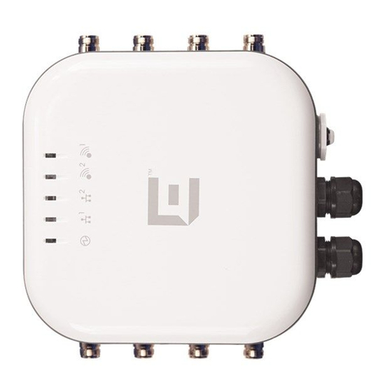
Introduction AP3965 Overview This chapter provides general information about the Extreme Networks Outdoor Access Point AP3965. AP3965 Overview The AP3965 (shown in Figure 1: AP3965e Front View on page 9) enables you to extend your wireless LAN beyond the boundaries of indoor locations. It is resistant to harsh outdoor conditions and extreme temperatures. - Page 9 Introduction Figure 1: AP3965e Front View AP Status Radio 1 (5 GHz) LAN 1 (Ethernet 1) LAN Ports (POE): • LAN 1 PDE Port • LAN 2 PSE Port output of DC48V, 0.26A LAN 2 (Ethernet 2) Console Port and Reset Button Radio 2 (2.4 GHz) Note The AP3965e provides eight external antenna ports.
- Page 10 Introduction Table 3: AP3965 LED Status Indicators Indicator Status Description 1 (AP status) On Green AP3965 working normally Flashing Green AP3965 running a self test or loading a software program On Amber CPU/system failure 2 (Ethernet link state) LAN 1 On Green Valid 100Mbps Ethernet link On Amber...
-
Page 11: Chapter 3: Installation
Installation Unpacking the AP3965 Separately Ordered Components AP3965 Installation Procedures Weatherproofing the AP3965e Connections Configuring AP3965 Channel Settings This chapter provides general information about the ExtremeWireless Outdoor Access Point AP3965. Unpacking the AP3965 Unpack the AP3965 as follows: Open the box and remove the packing material protecting the AP3965. 2 Verify that the contents of the carton contains the items listed below. -
Page 12: Separately Ordered Components
Installation 3 Perform a visual inspection of the AP3965 for any signs of physical damage. Contact Extreme Networks if there are any signs of damage. Separately Ordered Components The following accessories are available for the ExtremeWireless Access Point AP3965. For ordering information, contact Extreme Networks. - Page 13 Installation Install the AP3965 by following these procedures: • Ground Connection on page 13 • Mounting the AP3965 to a Wall on page 13 • Attaching the Mounting Bracket to the AP on page 14 • Mounting the AP3965 to a Pole on page 15 •...
- Page 14 Installation 2 Drill four holes into the wall as follows: • for installing the AP on a masonry wall, use a 5/16” diameter bit. • for other materials, use the appropriate drill for the screws being used. 3 For masonry installations, place four anchor assemblies into the holes. Attaching the Mounting Bracket to the AP Attach the mounting bracket to the AP3965 using four M4 screws, four spring washers, and four flat washers:...
- Page 15 Installation 4 If using #10 screws, tighten them to a torque of 25 in-lbs. If using ¼” screws, tighten them to 45 in- lbs. Figure 4: Mounting the AP3965 to a Wall Note Use anchors when mounting on cement walls. Mounting screws (shown above) are not included.
- Page 16 Installation 2 Attach the AP to the “H” bracket on the side that does not have the PEM stand-offs. Tighten the four screws to a torque of 12.0 in-lbs. 3 Using four M4 screw assemblies, attach the pole bracket onto the “H” bracket. Tighten the screws to 12.0 in-lbs.
- Page 17 Installation 5 Attach the two cable clamp to the pole bracket. Open the cable clamp by turning a flat bladed screwdriver counterclockwise. Then, insert the non-clamp end into the pole bracket through the holes. Note It is easier to install both clamps before attaching to the pole. Figure 6: Pole Mount Orientation 6 Put the metal band around the pole and insert it into the clamp.
- Page 18 Installation 8 Secure the AP to the pole by tightening the stainless steel tie back strap. Figure 7: AP3965 Pole Mount Option Mounting to a Pole with an Articulated Bracket How to attach the AP3965 to a pole using an articulating mount (WS-MBO-ART01). To attach the AP3965 and articulating mount to a pole: ExtremeWireless™...
- Page 19 Installation Figure 8: Articulating Mount (WS-MBO-ART01) for AP3965 Attach the small bracket on the WS-MBO-ART01 to the pole bracket with four M4 screws, verifying that the AP orientation will be upright before you tighten the brackets screws. Torque the screws to 12 in-lbs.
- Page 20 Installation Figure 9: Articulating Mount (WS-MBO-ART01) for AP3965 Use the small bracket holes as a template to mark the attachment holes in the wall, verifying that the AP orientation will be upright with the black glands at the bottom. Important The wall must be strong enough to support the AP during inclement weather.
- Page 21 Installation Attaching Antennas Install the external antennas intended for area coverage. For information about antenna selection and installation, refer to the ExtremeWireless External Antenna Site Preparation and Installation Guide. Note The total number of required antennas and associated port locations on the AP3965 depends on the coverage area and the type of antennas selected.
- Page 22 Installation Figure 11: RJ45 Cable Gland Adapter Assembly Sealing nut Claw Seal Main body Installing the Cable Gland Adapter Assembly Install the cable gland adapter assembly onto LAN 1 or LAN 2 as follows: Insert the RJ45 cable onto the sealing nut (shown below). ExtremeWireless™...
- Page 23 Installation 2 Slide the claw and seal onto the RJ45 cable (shown below). 3 Plug the RJ45 cable into the port (shown below). Caution Do not run the network cable through the cable conduit connector used for connecting the power cables. You must connect the network cable and power cables through separate connectors.
-
Page 24: Weatherproofing The Ap3965E Connections
6 Tighten the assembly by hand. Tighten the cap to 10 inch-pounds (shown below). Weatherproofing the AP3965e Connections Extreme Networks recommends that all connections between the AP and antennas are weatherproofed using one of the following weatherproof kits (not supplied): •... - Page 25 Installation Figure 12: Weatherproofing the AP3965e Antenna Antenna Standard polarity Type-N jack AP3965 Standard polarity Type-N plug Sealing tape (recommended, but not supplied) To weatherproof the antenna (refer to the figure above): Secure the antenna in place by tightening the single nut (item 2). 2 Seal the connection between the Type-N jack (item 4) of the AP3965e and the Type-N plug (item 3) of the antenna by wrapping a layer of sealing tape (item 6).
-
Page 26: Configuring Ap3965 Channel Settings
Installation Figure 13: Drip Loop for the AP3965e Configuring AP3965 Channel Settings The AP3965 must be installed by a professional installer. Before starting the installation, the installer needs to determine and configure the following: • Determine the Antenna Model on page 26 •... - Page 27 Installation Log into the Wireless Assistant. 2 From the top menu, click AP. The Wireless AP screen displays. 3 Select APs in the left pane, then in the list, click the Wireless AP whose properties you want to modify. The AP Properties tab displays Wireless AP information. Figure 14: AP Properties for the AP3965e ExtremeWireless™...
- Page 28 Installation 4 When configuring the AP3965e, click Professional Install. The Professional Install dialog displays to configure the external antennas. Figure 15: Prodessional Install Dialog 5 Modify the radio antenna type as follows: • If attaching quad port antennas, configure all four RF ports with the same antenna type. •...
- Page 29 Installation 3 Configure the desired Radio Mode, and Channel Width. Figure 16: AP3965e Radio 1 Properties — Base Settings 4 From the Request a New Channel drop-down menu, select a channel according to the site channel plan, or request the AP to auto select the channel from the channel list set in the Channel Plan setting.
- Page 30 Installation 3 Select AP in the left pane, then in the Wireless AP list, click the Wireless AP whose properties you want to modify. 4 Click the Radio 1 tab. 5 Max Tx Power is automatically determined based on regulatory domain/country, antenna selected, line attenuation configured, channel and certification testing.
-
Page 31: Appendix A: Specifications
Specifications Internal Antenna Access Points External Antennas This appendix lists the specifications for the ExtremeWireless Outdoor Access Point AP3965. Table 5: Specifications for the AP3965 Item Specification AP Part Numbers 31016 WS-AP3965i-FCC 31017 WS-AP3965i-ROW 31018 WS-AP3965e-FCC 31019 WS-AP3965e-ROW Enclosure material Metal enclosure IP67 rated Power source 802.3at or 802.3at+ compliant PoE... - Page 32 Specifications Table 6: AP3965i Internal Antennas Model Type Application Description Gain (dBi) Frequency (GHz) Connector AP3965i Indoor MU-MIMO 5dBi None 6dBi None The following radiation patterns apply to the antennas in the AP3965i only. In these diagrams, 0 degree is the AP's front and +/- 180 degree is the AP's back. Figure 19: Horizontal Radiation Pattern 2.4 GHz ExtremeWireless™...
- Page 33 Specifications Figure 20: Vertical Radiation Pattern 2.4 GHz Figure 21: Horizontal Radiation Pattern 5 GHz ExtremeWireless™ AP3965i & AP3965e Installation Guide...
-
Page 34: External Antennas
Specifications Figure 22: Vertical Radiation Pattern 5 GHz External Antennas The table below lists the external antennas for AP3965e. For more detailed specifications and radiation pattern diagrams, see the ExtremeWireless External Antenna Site Preparation and Installation Guide. Note All antennas are for an outdoor application with Standard Polarity Type-N connectors. Table 7: External Antennas for AP3965e Part No. - Page 35 Specifications Table 7: External Antennas for AP3965e (continued) Part No. (Short Frequency Band Antenna Type 2.4G Gain 5G Gain Shape Description) 30716 (WS- Sector 4.5-5 25-degree, AO-5Q05025N) sector, four-feed 30717 (WS- Sector 11-11.5 25-degree, AO-5Q11025N) sector, four-feed 30718 (WS-AO- 2.4G/5G Sector 10-10.5 6-7.5...
-
Page 36: Appendix B: Regulatory Information
Warnings identify essential information. Ignoring a warning can lead to problems with the application. Note Throughout this appendix, the term Extreme Networks AP3965 refers to the AP models AP3965i and AP3965e. Specific AP models are identified in this appendix only where it is necessary to do so. -
Page 37: Ap3965
Regulatory Information AP3965 Unless noted otherwise, the following regulatory information applies to both the AP3965i and the AP3965e. AP3965e External Antenna AP The AP3965e must be used only with certified external antennas. Any unused antenna ports must be terminated. For a list of approved external antennas, see External Antennas on page 34. -
Page 38: Canada
This Part 15 radio device operates on a non-interference basis with other devices operating at the same frequency when using the antennas provided or other Extreme Networks-certified antennas. Any changes or modifications to the product not expressly approved by Extreme Networks could void the user's authority to operate this device. - Page 39 Regulatory Information Industry Canada Compliance Statement This device complies with Industry Canada license-exempt RSS standard(s). Operation is subject to the following two conditions: (1) this device may not cause interference, and (2) this device must accept any interference, including interference that may cause undesired operation of the device. Le présent appareil est conforme aux CNR d'Industrie Canada applicables aux appareils radio exempts de licence.
-
Page 40: European Community
Parliament and of the Council of 8 June 2011 on the restriction of the use of certain hazardous substances in electrical and electronic equipment. The Extreme Networks ® AP3965i and AP3965e are designed for use in the European Union and other countries with similar regulatory restrictions where the end user or installer is allowed to configure the equipment for operation by entry of a country code relative to a specific country. - Page 41 1999/5/CE. Par la présente, Extreme Networks déclare que ce Radio LAN device est conforme aux exigences essentielles et aux autres dispositions de la directive 1999/5/CE qui lui sont applicables.
- Page 42 1999/5/CE. Spanish Por medio de la presente Extreme Networks declara que el Radio LAN device cumple con los requisitos esenciales y cualesquiera otras disposiciones aplicables o exigibles de la Directiva 1999/5/CE.
- Page 43 Regulatory Information • 2004/108/EC EMC Directive • EN 55011/CISPR 11, Class B, Group 1 ISM • EN 55022/CISPR 22, Class B • EN 55024/CISPR 24, includes IEC/EN 61000-4-2,3,4,5,6,11 • EN 61000-3-2 and -3-3 (Harmonics and Flicker) • EN 60601-1-2 (EMC immunity for medical equipment) •...
- Page 44 On the 5150- 5350 MHz band, channels 36, 40, 44, 48, 52, 56, 60, and 64 are restricted to indoor use only. The external antenna APs must only use antennas that are certified by Extreme Networks. The 2.4 GHz band, channels 1 - 13, may be used for indoor or outdoor use but there may be some channel restrictions.
- Page 45 Regulatory Information European Spectrum Usage Rules The AP configured with approved internal or external antennas can be used for indoor and outdoor transmissions throughout the European community as displayed in the following table. Some restrictions apply in Belgium, France, Greece, and Italy. Table 8: European Spectrum Usage Rules Country 5.15-5.25 (GHz)
-
Page 46: Certifications Of Other Countries
Regulatory Information Table 8: European Spectrum Usage Rules (continued) Country 5.15-5.25 (GHz) 5.25-5.35 (GHz) 5.47-5.725 (GHz) 2.4-2.4835 (GHz) Channels: Channels: Channels: Channels: 1 to 13 36,40,44,48 52,56,60,64 100,104,108,112,116, (Except Where 132,136,140 Noted) Slovenia Indoor only Indoor only Indoor or outdoor Indoor or outdoor Spain Indoor only... - Page 47 Regulatory Information • IEEE 802.11b/g (2.4 GHz) • IEEE 802.11n • IEEE 802.3at (PoE) • IEEE 802.3af (PoE) ExtremeWireless™ AP3965i & AP3965e Installation Guide...
-
Page 48: Ap3965E Approved External Antennas
Regulatory Information NCC Statement AP3965e Approved External Antennas The AP3965e external antenna AP can be used with certified external antennas. However, in order to comply with the local laws and regulations, an approval may be required by the local regulatory authorities.