
Related Manuals for Extreme Networks ExtremeWireless AP360i ExtremeWireless AP360e


Summary of Contents for Extreme Networks ExtremeWireless AP360i ExtremeWireless AP360e
- Page 1 ExtremeWireless™ AP360i/e Access Points Installation Guide 9036628-00 RevAA April 2020...
- Page 2 Copyright © 2020 Extreme Networks, Inc. All rights reserved. Legal Notice Extreme Networks, Inc. reserves the right to make changes in specifications and other information contained in this document and its website without prior notice. The reader should in all cases consult representatives of Extreme Networks to determine whether any such changes have been made.
-
Page 3: Table Of Contents
Table of Contents Preface...........................5 Text Conventions................................5 Documentation and Training..........................7 Getting Help..................................7 Subscribe to Service Notifications......................7 Providing Feedback..............................8 AP360i/e Overview......................9 AP360i/e Features..............................9 Power Source................................. 11 AP360i/e Power Tables............................12 LED Indicators................................12 Access Point Purchase Order Information..................... 14 Install the Access Point......................15 AP360i/e Box Contents............................15 Access Point Mounting Options and Bracket Information.............. - Page 4 Table of Contents Antenna socket radio mapping information....................41 Access Points Specifications................... 43 Product Specifications............................43 Regulatory Information....................44 Professional Installation Instruction........................44 Installation personnel............................44 External antenna............................... 44 Installation procedure............................. 45 Instructions d'installation professionnelle.....................45 Safety Guidelines............................... 45 Federal Communications Commission (FCC) Notice................45 Industry Canada Notice............................46 Detachable Antenna Usage..........................47 Australia Notice................................
-
Page 5: Preface
Preface This section describes the text conventions used in this document, where you can find additional information, and how you can provide feedback to us. Text Conventions Unless otherwise noted, information in this document applies to all supported environments for the products in question. - Page 6 Text Conventions Preface Table 1: Notes and warnings (continued) Icon Notice type Alerts you to... Caution Risk of personal injury, system damage, or loss of data. Warning Risk of severe personal injury. Table 2: Text Convention Description This typeface indicates command syntax, or represents information as screen displays it appears on the screen.
-
Page 7: Documentation And Training
Data Center products Other resources, like white papers, data sheets, and case studies Extreme Networks offers product training courses, both online and in person, as well as specialized certifications. For details, visit www.extremenetworks.com/education/. Getting Help If you require assistance, contact Extreme Networks using one of the following methods: Extreme Portal Search the GTAC (Global Technical Assistance Center) knowledge base;... -
Page 8: Providing Feedback
4. Select Submit. Providing Feedback The Information Development team at Extreme Networks has made every effort to ensure the accuracy and completeness of this document. We are always striving to improve our documentation and help you work better, so we want to hear from you. We welcome all feedback, but we especially want to know about: •... -
Page 9: Ap360I/E Overview
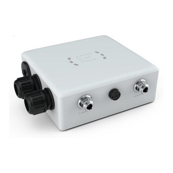
AP360i/e Overview AP360i/e Features on page 9 Power Source on page 11 AP360i/e Power Tables on page 12 LED Indicators on page 12 Access Point Purchase Order Information on page 14 The AP360i/e access points are outdoor model enterprise class 802.11ax access points. The “i” in AP360i indicates that the access point comes with internal antennas and the “e”... - Page 10 AP360i/e Features AP360i/e Overview ◦ One BLE internal antenna on AP360i and one BLE external antenna port on AP360e • Temperature: -40°C to +60°C (-40°F to +140°F) @ 6000 ft. • Enclosure: Plastic Figure 1: AP360i access point front view Callout Description Console port and reset button cap...
-
Page 11: Power Source
AP360i/e Overview Power Source Figure 2: AP360e access point front view Callout Description Console port and reset button cap GE1-PoE Vent Note The BLE antenna on the AP360e access point comes with a dust cap. Do not remove the dust cap until you need to install the antenna. -
Page 12: Ap360I/E Power Tables
AP360i/e Power Tables AP360i/e Overview AP360i/e Power Tables Table 4: AP360i power table AP360i 802.3af and 802.3at Radio 0 (sensor) 2.4G:2×2 (23 dBm) 5G:2×2 (21 dBm) Radio 0 (2.4G) 2×2 (23 dBm) Radio 0 (5G–L) 2×2 (20 dBm) Radio 1 (5G–F) 2×2 (21 dBm) Radio 1 (5G–H) 2×2 (20 dBm) - Page 13 AP360i/e Overview LED Indicators Figure 3: AP360i/e LED indicators Note The LED icons and the status on AP360i and AP360e are the same. Table 6: AP360i/e LED status indicators LED icon LED color Description Status Amber Non-operational status Green Normal operational status Amber 100 Mbps Green...
-
Page 14: Access Point Purchase Order Information
Access Point Purchase Order Information AP360i/e Overview Access Point Purchase Order Information The AP360i and AP360e access points must be ordered separately, the ordering details of which are presented in the following tables: Table 7: AP360i purchase order information Part number Description AP360i-FCC Dual-radio 802.11ax, 2×2:2, dual 5G outdoor internal antenna access... -
Page 15: Install The Access Point
Verify the box contents. 2. Visually inspect the access point, the bracket, and any other optional accessories you have ordered for physical damage. If there is any damage, contact Extreme Networks Support. 3. Read and review the safety guidelines. AP360i/e Box Contents... -
Page 16: Access Point Mounting Options And Bracket Information
Access Point Mounting Options and Bracket Information Install the Access Point Access Point Mounting Options and Bracket Information The access points can be mounted on a wall or to a pole by purchasing separate mounting brackets, which are described in the following table: Table 9: Mounting bracket usage Mounting bracket and Wall install... -
Page 17: Position The Access Point Before Installation
Install the Access Point Position the Access Point before Installation Table 9: Mounting bracket usage (continued) Mounting bracket and Wall install Pole install Notes part number WS-MBO-POLE01 Yes. The POLE01 bracket If the pole diameter is bracket can only be used with >= 1.0 in. -
Page 18: Install The Access Point To A Flat Surface Using Kt-147407-02 Flat Part And 1-Axis Tilt Part
Install the Access Point to a Flat Surface Using KT-147407-02 Flat Part and 1-Axis Tilt Part Install the Access Point • MBO-ART02 10 in. 2-axis articulating mounting bracket • WS-MBV-VMM vehicle bracket (#32216) Note The wall install options are applicable to both internal and external antenna model outdoor access points. -
Page 19: Install The Access Point To A Flat Surface Using The Kt-147407-02 Flat Part, 1-Axis Tilt Part, And The Kt- 150173-01 Extension Arm
Install the Access Point to a Flat Surface Using the KT-147407-02 Flat Part, 1-axis Tilt Part, and the KT- Install the Access Point 150173-01 Extension Arm Figure 5: KT-147407-02 bracket 1-axis tilt part Note The flat part and the 1-axis tilt part can be used interchangeably with the access points. You can either attach the flat part or the 1-axis tilt part first, and the rest of the installation procedure will not be affected by it. - Page 20 Install the Access Point to a Flat Surface Using the KT-147407-02 Flat Part, 1-axis Tilt Part, and the KT- 150173-01 Extension Arm Install the Access Point Figure 6: KT-150173-01 extension arm The following hardware is required for installation: • KT-147407-02 flat part •...
-
Page 21: Install The Access Point On A Flat Surface Using The Kt-150173-01 Extension Arm
Install the Access Point On a Flat Surface Using the Install the Access Point KT-150173-01 Extension Arm 5. Using four M6 hex-head screws, attach the KT-150173-01 extension arm to a flat surface. The best practice is to use screw-in anchors with the M6 screws on a wood surface, and concrete anchors on a concrete surface. - Page 22 Install the Access Point on a Flat Surface Using the MBO-ART02 Articulating Mounting Bracket Install the Access Point Procedure 1. Using the shorter end of the MBO-ART02 bracket end as a template, mark and drill four holes on the wall. Figure 7: MBO-ART02 articulating mounting bracket template for wall attachment holes 2.
-
Page 23: Install The Access Point On A Hard Vehicle Surface Using The Ws-Mbv-Vmm Vehicle Bracket (#32216)
Install the Access Point on a Hard Vehicle Surface Using Install the Access Point the WS-MBV-VMM Vehicle Bracket (#32216) Install the Access Point on a Hard Vehicle Surface Using the WS-MBV-VMM Vehicle Bracket (#32216) About This Task The WS-MBV-VMM vehicle bracket (#32216) is used to mount the access point on a wood or a metal vehicle surface. - Page 24 Install the Access Point on a Hard Vehicle Surface Using the WS-MBV-VMM Vehicle Bracket (#32216) Install the Access Point Procedure 1. Using the vehicle assembly plate four long inner slots as a template, mark and drill the attachment holes on a flat surface. Figure 8: VMM vehicle attach assembly plate Callout Description...
- Page 25 Install the Access Point on a Hard Vehicle Surface Using Install the Access Point the WS-MBV-VMM Vehicle Bracket (#32216) 3. Align the large holes on the stiffener plates with the large holes on the access point assembly plate, and attach the stiffener plates to the access point attach assembly plate. Figure 9: VMM access point attach assembly plate stiffener 1 and stiffener 2 Callout Description...
-
Page 26: Install The Access Point On A Pole
Install the Access Point on a Pole Install the Access Point Install the Access Point on a Pole You can install the access point on a pole using the following mounting brackets: • KT-147407-02 bracket parts • KT-147407-02 pole part •... -
Page 27: Attach The Access Point To A Pole Using All Three Kt-147407-02 Bracket Parts
Attach the Access Point to a Pole Using All Three Install the Access Point KT-147407-02 Bracket Parts Figure 10: KT-147407-02 pole part Note The pole install options are applicable to both internal and external antenna model outdoor access points. Attach the Access Point to a Pole Using All Three KT-147407-02 Bracket Parts Before You Begin The following hardware is required to mount the access point on to a pole: •... - Page 28 Attach the Access Point to a Pole Using All Three KT-147407-02 Bracket Parts Install the Access Point • KT-147407-02 pole part • Access point • Four M6 hex-head screws • Two hex-head M12 stainless-steel screws and nuts • Two 0.5 in. (12.7 mm) wide stainless-steel cable clamps About This Task To attach the access point to a pole: Procedure...
- Page 29 Attach the Access Point to a Pole Using All Three Install the Access Point KT-147407-02 Bracket Parts Figure 12: Large bracket holes on the pole part of the KT-147407-02 bracket Callout Description Large bracket holes used for attaching the M12 screws on the pole part of the KT-147407-02 bracket 3.
-
Page 30: Attach The Access Point To A Pole Using The Kt-147407-02 Pole Part
Attach the Access Point to a Pole Using the KT-147407-02 Pole Part Install the Access Point 4. Insert the 0.5 in. (12.7 mm) wide stainless-steel cable clamps through the long slots on the sides of pole bracket. Figure 13: Long slots on the pole part of the KT-147407-02 bracket Callout Description Long slots on the sides of the pole part of the KT-1474017-02 bracket. -
Page 31: Attach The Access Point To A Pole Using Kt-147407-02 Pole Part And The Kt-150173-01 Extension Arm
Attach the Access Point to a Pole Using KT-147407-02 Install the Access Point Pole Part and the KT-150173-01 Extension Arm Figure 14: Semi-circular cuts on the pole part of the KT-147407-02 bracket Callout Description Semi-circular cuts on the pole part of the KT-147407-02 bracket, used for attaching the M6 hex-head screws. -
Page 32: Attach The Access Point To A Pole Using The Kt-147407-02 Bracket Parts And The Kt-150173-01 Extension Arm
Attach the Access Point to a Pole Using the KT-147407-02 Bracket Parts and the KT-150173-01 Extension Arm Install the Access Point Procedure 1. Attach one end of the KT-150173-01 extension arm to the access point using two M6 hex-head screws. 2. - Page 33 Attach the Access Point to a Pole Using the KT-147407-02 Bracket Parts and the KT-150173-01 Install the Access Point Extension Arm 2. Align the circular holes on one end of the KT-150173-01 extension arm against the large holes on the 1-axis tilt part.
-
Page 34: Attach The Access Point To A Pole Using Ws-Mbo-Pole01 Bracket And Mbo-Art02 Articulating Mounting Bracket
Attach the Access Point to a Pole Using WS-MBO- POLE01 Bracket and MBO-ART02 Articulating Mounting Bracket Install the Access Point Attach the Access Point to a Pole Using WS-MBO-POLE01 Bracket and MBO-ART02 Articulating Mounting Bracket Before You Begin The following hardware is required: •... - Page 35 Attach the Access Point to a Pole Using WS-MBO- POLE01 Bracket and MBO-ART02 Articulating Mounting Install the Access Point Bracket 2. Attach the WS-MBO-POLE01 bracket to the MBO-ART02 articulating mounting bracket using four M3 screws, nuts, and washers. Figure 16: The POLE01 bracket being attached to the ART02 articulating mounting bracket 3.
- Page 36 Attach the Access Point to a Pole Using WS-MBO- POLE01 Bracket and MBO-ART02 Articulating Mounting Bracket Install the Access Point 6. Tighten the cable clamp screw clockwise, tightening the band around the pole. Figure 17: Tightening the cable clamp around the pole ExtremeWireless™...
-
Page 37: Ge And Console Connections
GE and Console Connections Cable Gland Adapter Assembly on page 37 The access points have two GE (Ethernet) ports and a Console port. During administration and maintenance through the GE or Console port, the access points must still have a power connection through an Ethernet PoE cable. - Page 38 Cable Gland Adapter Assembly GE and Console Connections About This Task Install the cable gland adapter assember onto the GE1 or GE2 port: Procedure 1. Insert the RJ45 cable onto the sealing nut. 2. Slide the claw and seal onto the RJ45 cable. ExtremeWireless™...
- Page 39 GE and Console Connections Cable Gland Adapter Assembly 3. Attach the main body into the GE1 or GE2 port of the access point. 4. Plug the RJ45 cable into the port. Caution Do not run the network cable through the cable conduit connector used for connecting the power cables.
-
Page 40: Safe Removal Of The Rj45 Cable
Safe Removal of the RJ45 Cable Procedure 1. Loosen the GE1 gland cap. 2. Move the gland cap, gland cage, and the gland gasket at least 6 in. away from the LAN cable and the gland area. 3. Use a thin, strong, and non-conductive tool like a flat-bladed orange stick to reach into the gland, and press down the plastic locking latch of the RJ45 connector. -
Page 41: Antenna Configuration For External Antenna Model Access Point
Antenna Configuration for External Antenna Model Access Point Figure 19: AP360e external antenna connectors Antenna socket radio mapping information • Radio 1 (R1) – antennas 3 and 4 • Radio 2 (R2) – antennas 1 and 2 Table 11: AP360e antenna configuration Software mode Radio 1 Radio 2... - Page 42 Antenna Configuration for External Antenna Model Antenna socket radio mapping information Access Point • Mode 3: Dual 5 GHz, radio 1 locked at 5 GHz low band, and radio 2 locked at 5 GHz high band Note The BLE antenna port comes with a dust cap on it. Do not remove the dust cap until you are ready to install the antenna.
-
Page 43: Access Points Specifications
Access Points Specifications Product Specifications Item Specification Dimensions 7.4in. × 5.7in. × 1.9in. (190.0 mm × 145.0 mm × 50.0 Weight 2.2 lbs. (1.0 kg) LEDs Housing IP67 rated for outdoor use Radios 2×2:2 5 GHz radio and 2×2:2 2.4 GHz radio 802.3af Console port RJ45... -
Page 44: Regulatory Information
Regulatory Information Professional Installation Instruction on page 44 Safety Guidelines on page 45 Federal Communications Commission (FCC) Notice on page 45 Industry Canada Notice on page 46 Detachable Antenna Usage on page 47 Australia Notice on page 48 Brazil Anatel Statement on page 48 Hazardous Substances on page 48... -
Page 45: Installation Procedure
Regulatory Information Installation procedure Installation procedure Refer to the installation instructions for details. Warning Select the installation position and make sure that the final output power does not exceed the limit set force in relevant rules. The violation of the rule could lead to serious federal penalty. Instructions d'installation professionnelle Personnel d'installation Ce produit est conçu pour une application spécifique et doit être installé... -
Page 46: Industry Canada Notice
Industry Canada Notice Regulatory Information a particular installation. If this equipment does cause harmful interference to radio or television reception, which can be determined by turning the equipment off and on, the user is encouraged to try to correct the interference by one of the following measures: •... -
Page 47: Detachable Antenna Usage
Regulatory Information Detachable Antenna Usage Warning Déclaration d'exposition aux radiations: Cet équipement est conforme aux limites d'exposition aux rayonnements ISED établies pour un environnement non contrôlé. Cet équipement doit être installé et utilisé avec un minimum de 31 cm de distance entre la source de rayonnement et votre corps. Detachable Antenna Usage This radio transmitter [4141B-AP360] has been approved by Innovation, Science and Economic Development Canada to operate with the antenna types listed below, with the maximum permissible... -
Page 48: Australia Notice
Australia Notice Regulatory Information Group Brand Model number Antenna type Antenna gain (dBi) 2.4 GHz 5 GHz BLE or thread Extreme WS-AI- Panel 2 10.5 DE10055 Extreme ML-2499- Dipole HPA8-01 Australia Notice AU co-location MPE Statement This equipment complies with AU radiation exposure limits set forth for an uncontrolled environment. This equipment should be installed and operated with minimum distance of 24 cm between the radiator and your body. -
Page 49: Supplement To Product Instructions
Regulatory Information Supplement to Product Instructions Supplement to Product Instructions NCC Statement ExtremeWireless™ AP360i/e Access Points... -
Page 50: Ce Information
CE Information Regulatory Information CE Information The device is restricted to indoor use only when operating in the 5150 to 5350 MHz frequency range. Warning CE co-location MPE Statement: This equipment complies with CE radiation exposure limits set forth for an uncontrolled environment. -
Page 51: Declaration Of Conformity In Languages Of The European Community
French Par la présente Extreme Networks déclare que l'appareil Radio LAN device (AP360i/e) est conforme aux exigences essentielles et aux autres dispositions pertinentes de la directive 2014/53/EU. Pour obtenir le texte intégral du processus de Déclaration de la conformité... - Page 52 κανονιστική συμμόρφωση στο compliancerequest@extremenetworks.com Icelandic Extreme Networks lysir her med yfir að thessi bunadur, Radio LAN device (AP360i/e), uppfyllir allar grunnkrofur, sem gerdar eru i R&TTE tilskipun ESB nr 2014/53/EU. Fyrir fullan texta í ESB yfirlýsingu um samræmi, vinsamlegast hafðu samband við Extreme Reglufylgni á...
-
Page 53: Index
Index antenna configurations install the access point AP360e access point antenna connectors 41 AP360e box contents 15 AP360i/e mounting options AP360e installation 15 KT-147407-02 bracket 16 AP360i box contents 15 KT-150173-01 extension arm 16 AP360i installation 15 MBO-ART02 articulating mounting bracket 16 box contents 15 optional bracket 16 installation procedure pole install 16 flat Surface install 17 wall install 16... - Page 54 Index mounting option (continued) pole mounting (continued) KT-150173-01 extension arm with KT-147407-02 pole part 26 POLE01 bracket with ART02 articulating mounting bracket 26 VMM bracket installation 23 NCC statement 49 notices 5 overview AP360e 9 AP360i 9 firmware use 9 POLE01 bracket and the ART02 bracket pole install 34 power table AP360e power table 12 AP360i power table 12...