
Related Manuals for Extreme Networks ExtremeWireless WS-AP3915i-FCC


Summary of Contents for Extreme Networks ExtremeWireless WS-AP3915i-FCC
- Page 1 ™ ExtremeWireless AP3915i FCC/ROW Installation Guide 9035129 Published September 2017...
- Page 2 Copyright © 2017 Extreme Networks, Inc. All rights reserved. Legal Notice Extreme Networks, Inc. reserves the right to make changes in specifications and other information contained in this document and its website without prior notice. The reader should in all cases consult representatives of Extreme Networks to determine whether any such changes have been made.
-
Page 3: Table Of Contents
Table of Contents Preface............................4 Text Conventions...................................4 Providing Feedback to Us..............................4 Getting Help.....................................5 Extreme Networks Documentation..........................5 Chapter 1: Overview........................6 Features..................................... 6 LED Indicators..................................7 Chapter 2: Installation Process....................9 Verifying the Box Contents.............................. 9 Mounting to a Dry/Wood Wall or Solid Flat Ceiling...................10 Mounting to a Junction/Gang box..........................13... -
Page 4: Preface
Preface Text Conventions The following tables list text conventions that are used throughout this guide. Table 1: Notice Icons Icon Notice Type Alerts you to... General Notice Helpful tips and notices for using the product. Note Important features or instructions. Caution Risk of personal injury, system damage, or loss of data. -
Page 5: Getting Help
Preface If you would like to provide feedback to the Extreme Networks Information Development team about this document, please contact us using our short online feedback form. You can also email us directly at internalinfodev@extremenetworks.com. Getting Help If you require assistance, contact Extreme Networks using one of the following methods: •... -
Page 6: Chapter 1: Overview
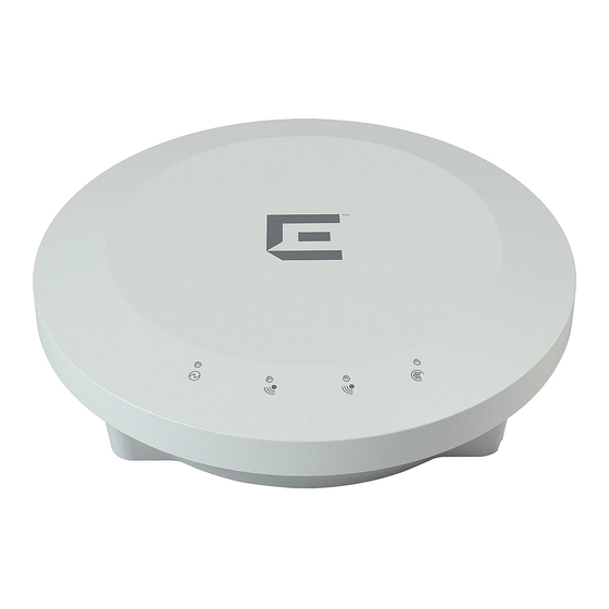
Overview Features LED Indicators The AP3915i is an 11ac Wave 2, Cloud and IoT ready indoor ceiling mount model with 5 internal antennas. This AP comes with an 802.3 PoE PD for powering. The AP3915i features dual-band, dual radio,2 x Multi-User MIMO, smoke-detector footprint, and can be mounted on a dry wall, on a ceiling or a solid surface, and suspended on a ceiling. -
Page 7: Led Indicators
Overview Table 3: AP3915i Features (continued) Item Description 3 - Console Port Console RJ45 Connector. 4 - Reset Button Use a tool to access the reset button to reset the AP. LED Indicators AP3915i Access Points have LED indicators on the front of the box. The LEDs provide the status of the access point indicating on, off,and network activity. - Page 8 Overview Table 4: AP3915 LEDs (continued) Item Status Description Green Indicates radio is enabled. 2 (2.4 GHz radio) Green Indicates radio is enabled. 3 (5 GHz radio) Blue Indicates IoT application is running. 4 (IoT Radio) Both the Radio LEDs will be Green when they are ON and the LEDs will not have any lights when they are OFF.
-
Page 9: Chapter 2: Installation Process
AP3915i Quick Reference Guide ExtremeCloud ™ Quick Start Card WS-AP3915i AP 2 Perform a visual inspection of the AP for any signs of physical damage. Contact Extreme Networks if there are any signs of damage. Note Before mounting the AP3915i, read the Safety Guidelines. -
Page 10: Mounting To A Dry/Wood Wall Or Solid Flat Ceiling
Installation Process Mounting to a Dry/Wood Wall or Solid Flat Ceiling Mounting the AP3915i to a dry/wood wall or a solid flat ceiling requires WS-MBI-WALL04 bracket, two Philips pan-head screws, and screw-in anchors, which must be purchased separately. Warning The AP must be mounted ONLY horizontally when mounting onto a plenum space. Note The recommended method of installation is using the WS-MBI-WALL04 bracket and the Multi T-bar bracket. - Page 11 Installation Process Install the WS-MBI-WALL04 bracket on a wall/ceiling with the two screws and screw-in anchors. Ensure that the locking tab on the WS-MBI-WALL04 bracket is on the bottom side during installation. Figure 3: Mounting the AP using the WS-MBI-WALL04 Bracket •...
- Page 12 Installation Process 3 Insert the AP onto the keyhole posts and slide the AP. 4 Lock the AP into place at about 1/4 inch. Optional Installation: Mounting to a wall using the Philips Pan-head screws You can mount the AP3915i access point directly onto a dry/solid wall using the Philips Pan-Head screws.
-
Page 13: Mounting To A Junction/Gang Box
Installation Process 4 Align the AP against the screw heads and slide it down. Ensure that the AP is secured in place and tightened. If the AP is loose, unmount the AP and decrease the distance between the screw head and the wall. - Page 14 Installation Process 2 Open the movable sliding part of the T-bar to give the stationary and slider T-bar more space. Figure 5: Installing the T-bar adaptor 3 Hook the stationary end of the T-bar bracket onto the T-bar. 4 Tilt the T-bar up slightly in such a way that you are holding the stationary and movable sides of the bracket.
-
Page 15: Connecting The Power Supply
Installation Process 5 Slide the T-bar ceiling mount bracket base into the back of the access point. The locking tab fits into a groove in the outside of the AP. Figure 6: Mounting the AP3915i to the T-bar 6 Hold the AP and rock it back and forth to ensure that it is securely mounted. 7 Attach the Ethernet cable’s RJ45 connector to the LAN1/GE1 port and place the ceiling tile back in place. - Page 16 Installation Process Table 6: AP3915i Power Supply Options AP3915i Port Function LAN1/GE1 Port Optional 12V DC Power Supply When the device is powered on, the power LED on the front face of the AP is lit. ExtremeWireless™ AP3915i FCC/ROW Installation Guide...
-
Page 17: Chapter 3: Specifications
Specifications This section lists the specifications for the ExtremeWireless™ Indoor Access Point AP3915i. Table 7: Specifications for the AP3915i Item Specification AP Part Number: 31028 WS-AP3915i-FCC AP Part Number: 31029 WS-AP3915i-ROW Enclosure material AP enclosure is plastic only. Power source Power is provided by Power-over-Ethernet 802.3af. -
Page 18: Chapter 4: Regulatory Information
Regulatory Information Safety Guidelines FCC Declaration of Conformity Statement FCC Radiation Exposure Statement Industry Canada Notice European Waste Electrical and Electronic Equipment (WEEE) Notice Hazardous Substances Declaration of Conformity in Languages of the European Community Safety Guidelines This section contains notices that are intended to protect your personal safety and prevent damage to the equipment. -
Page 19: Fcc Radiation Exposure Statement
Regulatory Information FCC Caution: Any changes or modifications not expressly approved by the party responsible for compliance could void the user's authority to operate this equipment. This device complies with Part 15 of the FCC Rules. Operation is subject to the following two conditions: •... - Page 20 Regulatory Information Caution Avertissement: les dispositifs fonctionnant dans la bande 5150-5250 MHz sont réservés uniquement pour une utilisation à l’intérieur afin de réduire les risques de brouillage préjudiciable aux systèmes de satellites mobiles utilisant les mêmes canaux. 2 le gain maximal d'antenne permis (pour les dispositifs utilisant la bande de 5725 à 5 850 MHz) doit être conforme à...
-
Page 21: European Waste Electrical And Electronic Equipment (Weee) Notice
Changes or modifications made to this device which are not expressly approved by the party responsible for compliance could void the user’s authority to operate the equipment. English Hereby, Extreme Networks, Inc. declares that the radio equipment type Wireless LAN Access Point is in compliance with Directive 1999/5/EC. Finnish Valmistaja Extreme Networks vakuuttaa täten että... -
Page 22: New Member States Requirements Of Declaration Of Conformity
Regulatory Information Extreme Networks dat deze Radio LAN device voldoet aan de essentiële eisen en aan de overige relevante bepalingen van Richtlijn 1999/5/EC. French Par la présente Extreme Networks déclare que l'appareil Radio LAN device est conforme aux exigences essentielles et aux autres dispositions pertinentes de la directive 1999/5/ CE. Par la présente, Extreme Networks déclare que ce Radio LAN device est conforme aux exigences...