Table of Contents
Advertisement
Quick Links
Advertisement
Table of Contents

Related Manuals for Extreme Networks ExtremeWireless AP3965i


Summary of Contents for Extreme Networks ExtremeWireless AP3965i
- Page 1 ExtremeWireless™ AP3965i & AP3965e Installation Guide P/N 9034917 January 2016...
-
Page 2: Legal Notices
Copyright © 2016 Extreme Networks, Inc. All Rights Reserved. Legal Notices Extreme Networks, Inc. reserves the right to make changes in specifications and other information contained in this document and its website without prior notice. The reader should in all cases consult representatives of Extreme Networks to determine whether any such changes have been made. -
Page 3: Table Of Contents
Contents About This Guide Who Should Use This Guide ..........................v How to Use This Guide ............................v Related Documents ............................vi Typographical Conventions ..........................vi Chapter 1: Introduction AP3965 Overview .............................. 1 AP3965 LED Indicators ..........................2 Antennas ..............................3 External Antenna Connectors ........................3 LAN Ports .............................. - Page 4 Other ..............................35 FCC RF Radiation Exposure Statement ....................35 External Antennas ............................. 35 Professional Installation Notice ......................... 36 Canada ................................36 Industry Canada Compliance Statement ....................36 Canada Conformance Standards ......................37 Safety..............................37 EMC..............................37 Radio transceiver ..........................37 Other ..............................
-
Page 5: About This Guide
About This Guide The guide describes how to mount and connect cables to the ExtremeWireless™ Outdoor Access Point AP3965. In addition, this guide provides information on the product certifications and national approvals for the AP3965. Note: This guide does not provide information on configuration of the AP3965. For information on how to configure the AP3965, see the ExtremeWireless™ User Guide. Who Should Use This Guide WARNING Electrical Hazard: Only qualified personnel should install or service this unit. Riesgo Electrico: Nada mas personal capacitado debe de instalar o darle servicio a esta unida. -
Page 6: Related Documents
About This Guide Related Documents The manuals listed below can be obtained from the World Wide Web in Adobe Acrobat Portable Document Format (PDF) at the following site: https://Extremenetworks.com/downloads/ • ExtremeWireless™ External Antenna Site Preparation and Installation Guide • ExtremeWireless™ User Guide Typographical Conventions The following typographical conventions and icons are used in this document. blue type Indicates a hypertext link. When reading this document online, click the text in blue to go to the referenced figure, table, or section. Lowercase x Indicates the general use of an alphanumeric character (for example, 6x1xx, the x’s indicate a combination of numbers or letters). -
Page 7: Ap3965 Overview
Introduction This chapter provides general information about the ExtremeWireless™ Outdoor Access Point AP3965. For information about... Refer to page... AP3965 Overview AP3965 LED Indicators Antennas External Antenna Connectors LAN Ports AP Part Numbers AP3965 Overview The AP3965 (see Figure 1‐1 on page 2) enables you to extend your wireless LAN beyond the boundaries of indoor locations. It is resistant to harsh outdoor conditions and extreme temperatures. Using the advanced full mesh wireless distribution feature of the wireless LAN, the AP3965 can extend your wireless LAN to outdoor locations without Ethernet cabling. A mounting bracket is available to enable quick and easy mounting of the AP3965 to walls and poles. The AP3965 is an 802.11ac AP that supports 802.11a/802.11g and 802.11b legacy devices. It is delivered in a rugged enclosure. The AP3965 interoperates fully with the wireless LAN, including support for wireless VoWLAN, branch office mode, availability and mobility features. The AP3965i provides eight internal antennas. The AP3965e supports a variety of external antennas, providing range and coverage versatility. ExtremeWireless™ AP3965 Installation Guide 1... -
Page 8: Ap3965 Led Indicators
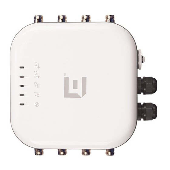
AP3965 Overview Figure 1-1 AP3965e Front View AP Status Radio 1 (5 GHz) LAN 1 (Ethernet 1) LAN Ports (POE): • LAN 1 PDE Port • LAN 2 PSE Port output of DC48V, 0.26A LAN 2 (Ethernet 2) Console Port and Reset Button Radio 2 (2.4 GHz) Note: The AP3965e provides eight external antenna ports. -
Page 9: Antennas
AP3965 Overview Table 1-1 AP3965 LED Status Indicators (Continued) Indicator Status Description 2 (Ethernet link state) LAN 1 On Green Valid 100Mbps Ethernet link On Amber Valid 1Gbps Ethernet link Link down 3 (Ethernet link state) LAN 2 On Green Valid 100Mbps Ethernet link On Amber Valid 1Gbps Ethernet link... - Page 10 AP3965 Overview 4 Introduction...
-
Page 11: Chapter 2: Installation
Installation This chapter provides installation instructions for the ExtremeWireless™ Outdoor Access Point AP3965. For information about... Refer to page... Unpacking the AP3965 Separately Ordered Components AP3965 Installation Procedures Weatherproofing the AP3965e Connections Configuring AP3965 Channel Settings Unpacking the AP3965 Unpack the AP3965 as follows: Open the box and remove the packing material protecting the AP3965. Verify that the contents of the carton contains the items listed in Table 2‐1. Table 2-1 Contents of the AP3965 Carton Quantity Item AP3965 Quick Reference... -
Page 12: Separately Ordered Components
Installation Separately Ordered Components Quantity Item Screw assemblies, size M4, that include the screws, flat washers, and split washers. Ground Screw assembly, size M4, that include the screw, star washer, and split washer. Optional: You may also need antennas, terminators, or cables. Refer to www.extremenetworks.com/support for product numbers. Note: ” on page 46 Before mounting the AP3965, read the “RF Safety Distance Perform a visual inspection of the AP3965 for any signs of physical damage. Contact Extreme ... -
Page 13: Ap3965 Installation Procedures
AP3965 Installation Procedures Installation AP3965 Installation Procedures Use these instructions as guidelines for mounting and connecting the AP3965 easily and safely. The installation of the AP3965 should be performed by a professional installer to ensure proper operation and compliance with local safety guidelines. Attach the AP3965 to a surface that can support it and withstand its environment. It can be mounted to a wall, girder, ceiling, or pole, and the surface material can be concrete, brick, wood, metal, or plastic. Warning: This product should be installed and serviced by a qualified licensed technician, electrician, or electrical maintenance person familiar with its operation and the hazards involved. Install the AP3965 by following these procedures: •... -
Page 14: Mounting The Ap3965 To A Wall
Installation AP3965 Installation Procedures Figure 2-1 AP3965 Ground Terminal Location Mounting the AP3965 to a Wall Mount the AP so that the glands are on the side of the AP closest to the ground, and not above the plastic cover. You must provide a 3‐inch drip loop on all cables. For more information, see “Forming a Drip Loop for AP3965e Cables” on page 19. Using the mounting bracket as a guide, mark the location for the mounting screws on a horizontal, flat wall surface. Drill four holes into the wall as follows: – for installing the AP on a masonry wall, use a 5/16” diameter bit. – for other materials, use the appropriate drill for the screws being used. For masonry installations, place four anchor assemblies into the holes. Attach the Mounting Bracket to the AP Attach the mounting bracket to the AP3965 using four M4 screws, four spring washers, and four flat washers: Use 4 M4 screw assemblies to attach the AP to the “H” bracket on the side that does not have the PEM stand‐offs. Tighten the four screws to a torque of 12.0 in‐lbs. ... -
Page 15: Mounting Bracket Orientation
AP3965 Installation Procedures Installation Figure 2-2 Mounting Bracket Orientation Secure the anchors to the wall, then secure the bracket to the anchors. See Figure 2‐3 on page If using #10 screws, tighten them to a torque of 25 in‐lbs. If using ¼” screws, tighten them to 45 in‐lbs. ExtremeWireless™ AP3965 Installation Guide 9... -
Page 16: Mounting The Ap3965 To A Pole
Installation AP3965 Installation Procedures Figure 2-3 Mounting the AP3965 to a Wall Note: Use anchors when mounting on cement walls. (Not shown above.) Mounting screws (shown above) are not included. Mounting the AP3965 to a Pole To fit the mounting plate to a pole: Determine the diameter of the pole. Pole Diameter Cable Clamp Size <= 2.5”... -
Page 17: Attach Pole Bracket To "H" Bracket
AP3965 Installation Procedures Installation Figure 2-4 Attach Pole Bracket to “H” Bracket Attach the two cable clamp to the pole bracket. Open the cable clamp by turning a flat bladed screwdriver counterclockwise. Then, insert the non‐clamp end into the pole bracket through the holes. Note: It is easier to install both clamps before attaching to the pole. ExtremeWireless™ AP3965 Installation Guide 11... -
Page 18: Pole Mount Orientation
Installation AP3965 Installation Procedures Figure 2-5 Pole Mount Orientation Put the metal band around the pole and insert it into the clamp. Turn the clamp screw clockwise, tightening the band around the pole. Secure the pole mount bracket to the AP mounting bracket using four M4 screws. Secure the AP to the pole by tightening the stainless steel tie back strap (see Figure 2‐6). Figure 2-6 AP3965 Pole Mount Option... -
Page 19: Attaching Antennas
AP3965 Installation Procedures Installation Attaching Antennas Install the external antennas intended for area coverage. For information about antenna selection and installation, refer to the ExtremeWireless™ External Antenna Site Preparation and Installation Guide. Notes: The total number of required antennas and associated port locations on the AP3965 depends on the coverage area and the type of antennas selected. To attach external antennas to the AP3965: Attach the external antenna cables to the Standard Polarity Type‐N connectors on the AP3965. All the antennas can be extended away from the AP using the optional cables. Place a terminator cap on any antenna connectors that will not be used (see Figure 2‐7 on page 13). Do not install the AP with the antennas pointing upward. The recommend installation has the ... -
Page 20: Installing The Cable Gland Adapter Assembly
Installation AP3965 Installation Procedures Figure 2-8 RJ45 Cable Gland Adapter Assembly 1 Sealing nut 2 Claw Seal Main body Installing the Cable Gland Adapter Assembly Install the cable gland adapter assembly onto LAN 1 or LAN 2 as follows: Insert the RJ45 cable onto the sealing nut. Slide the claw and seal onto the RJ45 cable. Plug the RJ45 cable into the port. - Page 21 AP3965 Installation Procedures Installation Caution: Do not run the network cable through the cable conduit connector used for connecting the power cables. You must connect the network cable and power cables through separate connectors. ExtremeWireless™ AP3965 Installation Guide 15...
- Page 22 Installation AP3965 Installation Procedures Slide the seal and claw into the main body. Secure the seal nut onto the main body. Tighten the assembly by hand. Tighten the cap to 10 inch pounds.
-
Page 23: Weatherproofing The Ap3965E Connections
Weatherproofing the AP3965e Connections Installation Weatherproofing the AP3965e Connections Extreme Networks recommends that all connections between the AP and antennas are weatherproofed using one of the following weatherproof kits (not supplied): • Wireless Weatherproofing Kits: – 3M (WK‐100) – Scotch (WK‐101) Each weatherproofing kit includes 3/4 inch vinyl tape, 2 inch mastic tape, and 2 inch vinyl tape. • Cold Shrink Kits: – 3M Cold Shrink Sealing Kit CXS (CXS‐4). – 3M Cold Shrink EDPM Connector Insulator (8426‐9M) The cold shrink kit includes one tube of vinyl mastic, and 2 inch mastic tape. ExtremeWireless™ AP3965 Installation Guide 17... -
Page 24: Weatherproofing The Antenna
Installation Weatherproofing the AP3965e Connections Weatherproofing the Antenna The following guidelines should be followed to ensure proper installation: • The weatherproofing tape must be wound tightly over the connectors. • Care should be taken to ensure that no areas around the edges are exposed. Note: Installation instructions are provided with each weatherproofing kit and are included here for reference only Figure 2‐9 shows how to wrap the antenna mounted directly to the AP3965e. Do not install the AP with the antennas pointing upward. The recommend installation has the antennas extended horizontally. Figure 2-9 Weatherproofing the AP3965e Antenna Antenna Standard polarity Type-N jack AP3965 Standard polarity Type-N plug Sealing tape (recommended, but not supplied) To weatherproof the antenna (refer to Figure 2‐9): Secure the antenna in place by tightening the single nut (item 2). -
Page 25: Forming A Drip Loop For Ap3965E Cables
Configuring AP3965 Channel Settings Installation Forming a Drip Loop for AP3965e Cables Once the cables have been connected to the AP and the connections have been weatherproofed, gather each cable below the AP, and form a drip loop as shown in Figure 2‐10. Note: The drip loop prevents water from entering the AP by channeling water down and away from the connection points. Drip loops are required to ensure proper operation of the AP. -
Page 26: Determine The Antenna Model
Installation Configuring AP3965 Channel Settings • Determine the Antenna Model • Configure Radio RF Port • Configure Radio Channel • Configure Radio Transmit (Tx) Power Determine the Antenna Model The professional installer needs to determine antenna models and the number of antenna ports for that model. The number of ports can be determined from visual inspection of the antenna or from the antenna model. For information about antenna models, see AP3965e, Table A‐3 on page 30. Configure Radio RF Port The professional installer configures Radio RF ports where antenna ports will be connected. To Configure Radio RF Ports through the ExtremeWireless™ Assistant: Log into the Wireless Assistant. From the top menu, click AP. The Wireless AP screen is displayed. Select APs in the left pane, then in the Wireless AP list, click the Wireless AP whose properties you want to modify. The AP Properties tab displays Wireless AP information. -
Page 27: Ap Properties For The Ap3965E
Configuring AP3965 Channel Settings Installation Figure 2-11 AP Properties for the AP3965e ExtremeWireless™ AP3965 Installation Guide 21... -
Page 28: Configure Radio Channel
Installation Configuring AP3965 Channel Settings When configuring the AP3965e, click Professional Install. The Professional Install dialog displays to configure the external antennas. Modify the Radio Antenna Type as follows: – If attaching quad port antennas, configure all four RF ports with the same antenna type. – If attaching triple port antennas, configure ports 1, 2, and 3 with the same antenna type and configure port 4 (non‐active port) to No Antenna. – If attaching dual port antennas, configure ports 1 and 2 with the same antenna type and configure ports 3 and 4 (non‐active ports) to No Antenna. – If attaching single port antennas, configure port 1to the selected antenna type and configure ports 2‐4 (non‐active ports) to No Antenna. Modify Radio Attenuation as follows: – Add any attenuation (dBm non‐negative) due to cable loss or attenuator added to the line between AP port and the antenna. – Same attenuator loss is assumed and is required for all 4 ports of the radio except when one or more ports is not connected to the antenna and is properly terminated as describe in next step. – The professional installer is responsible for accurately configuring port Attenuation. Never configure port attenuation higher than the actual attenuation between the AP port and the antenna. Install a terminator (rf 50 Ohm) on all ports where an antenna is not connected. Configure Radio Channel Click APs in the left pane, then in the Wireless AP list, click the Wireless AP whose properties you want to modify. The AP Properties tab displays Wireless AP information. -
Page 29: Ap3965E Radio 1 Properties: Base Settings
Configuring AP3965 Channel Settings Installation Click the Radio 1 tab. Configure the desired Radio Mode, and Channel Width. Figure 2-12 AP3965e Radio 1 Properties: Base Settings From the Request a New Channel drop‐down menu, select a channel according to the site channel plan, or request the AP to auto select the channel from the channel list set in the Channel Plan setting. ExtremeWireless™ AP3965 Installation Guide 23... -
Page 30: Configure Radio Transmit (Tx) Power
Installation Configuring AP3965 Channel Settings Figure 2-13 AP3965e Radio 1 Properties: Channel Plan setting Repeat the process for Radio 2. Configure Radio Transmit (Tx) Power Based on the configured mode, channel, channel plan, and channel width for the specific antenna, the professional installer must enter the corresponding Transmit Power (Tx Power) for the desired Radio using the ExtremeWireless™ Assistant. Log into the Wireless Assistant. From the top menu, click AP. The Wireless AP screen is displayed. Select AP in the left pane, then in the Wireless AP list, click the Wireless AP whose properties you want to modify. The AP Properties tab displays Wireless AP information. Click the Radio 1 tab. Max Tx Power is automatically determined based on regulatory domain/country, antenna selected, line attenuation configured, channel and certification testing. Max Tx Power refers • Current channel if the radio is up and Request New Channel is not set • Request Channel if it is set to a supported channel • If Request Channel is set to Auto, then Max Tx Power is limited to the lowest power channel configured in the Channel plan. -
Page 31: Ap3965E Radio 1 Properties: Max Tx Power Setting
Configuring AP3965 Channel Settings Installation Figure 2-14 AP3965e Radio 1 Properties: Max TX Power setting The professional installer is responsible for accurately configuring port Attenuation. Port attenuation should never be configured higher than the actual attenuation between the AP port and the antenna. Repeat the process for Radio 2. ExtremeWireless™ AP3965 Installation Guide 25... - Page 32 Installation Configuring AP3965 Channel Settings...
-
Page 33: Appendix A: Specifications
Specifications This appendix lists the specifications for the ExtremeWireless™ Outdoor Access Point AP3965. Table A-1 Specifications for the AP3965 Item Specification AP Part Numbers 31016 WS-AP3965I-FCC 31017 WS-AP3965I-ROW 31018 WS-AP3965E-FCC 31019 WS-AP3965E-ROW Enclosure material Metal enclosure IP67 rated Power source 802.3at or 802.3at+ compliant PoE Power consumption < 22W (Max.) when operating as AP only <... -
Page 34: Internal Antenna Access Points
Specifications Internal Antenna Access Points Internal Antenna Access Points The AP3965i is an indoor access with eight integrated internal antennas. The following specifications are for the internal antennas: Table A-2 AP3965i Internal Antennas Gain Model Type Application Description (dBi) Frequency (GHz Connector AP3965i Indoor MU-MIMO 5dBi None 6dBi None The following radiation patterns apply to the antennas in the AP3965i only. In these diagrams, 0 degree is the APʹs front and +/‐ 180 degree is the APʹs back. Horizontal Radiation Pattern 2.4 GHz... -
Page 35: Vertical Radiation Pattern 2.4 Ghz
Internal Antenna Access Points Specifications Vertical Radiation Pattern 2.4 GHz Horizontal Radiation Pattern 5 GHz ExtremeWireless™ AP3965 Installation Guide 29... -
Page 36: Vertical Radiation Pattern 5 Ghz
Specifications External Antennas Vertical Radiation Pattern 5 GHz External Antennas Table A‐3 lists the external antennas for AP3965e. For more detailed specifications and radiation pattern diagrams, see the ExtremeWireless™ External Antenna Site Preparation and Installation Guide. NOTE All antennas are for an outdoor application with Standard Polarity Type-N connectors. Table A-3 External Antennas for AP3965e Part No. Frequency Antenna 2.4G (Short Description) Band Type Gain Gain... - Page 37 External Antennas Specifications Table A-3 External Antennas for AP3965e Part No. Frequency Antenna 2.4G (Short Description) Band Type Gain Gain Shape 30715 (WS-AO-DE13025N)* 2.4G/5G Sector 11-12 25-degree, sector, eight-feed 30716 (WS-AO-5Q05025N) Sector 4.5-5 25-degree, sector, four-feed 30717 (WS-AO-5Q11025N) Sector 11-11.5 25-degree, sector, four-feed 30718 (WS-AO-DE10055N)
- Page 38 Specifications External Antennas...
-
Page 39: Regulatory Information
Warning Changes or modifications made to the ExtremeWireless™ AP3965 that are not expressly approved by Extreme Networks could void the user's authority to operate the equipment. Only authorized Extreme Networks service personnel are permitted to service the system. -
Page 40: Appendix B: Regulatory Information Ap3965
Regulatory Information AP3965 Warning Electrical Hazard: Only qualified personnel should perform installation procedures. Within the context of the safety notes in this documentation qualified persons are defined as persons who are authorized to commission, ground and label devices, systems and circuits in accordance with established safety practices and standards. -
Page 41: Emc
Extreme Networks-certified antennas. Any changes or modifications to the product not expressly approved by Extreme Networks could void the user's authority to operate this device. For the product available in the USA market, only channels 1 to 11 can be operated. -
Page 42: Professional Installation Notice
Regulatory Information Canada For a list of approved external antennas, see “External Antennas” on page 30. Professional Installation Notice To comply with FCC part 15 rules in the United States, the system must be professionally installed to ensure compliance with the Part 15 certification. It is the responsibility of the operator and professional installer to ensure that only certified systems are deployed in the United States. The use of the system in any other combination (such as co‐located antennas transmitting the same information) is expressly forbidden. Canada Industry Canada Compliance Statement This device complies with Industry Canada license‐exempt RSS standard(s). Operation is subject to the following two conditions: (1) this device may not cause interference, and (2) this device must accept any interference, including interference that may cause undesired operation of the device. Le présent appareil est conforme aux CNR dʹIndustrie Canada applicables aux appareils radio exempts de licence. Lʹexploitation est autorisée aux deux conditions suivantes : (1) lʹappareil ne doit pas produire de brouillage, et (2) lʹutilisateur de lʹappareil doit accepter tout brouillage radioélectrique subi, même si le brouillage est susceptible dʹen compromettre le fonctionnement. This radio transmitter (IC: 4141B‐4411OAC) has been approved by Industry Canada to operate with the antenna types listed below with the maximum permissible gain and required antenna impedance for each antenna type indicated. Antenna types not included in this list, having a gain greater than the maximum gain indicated for that type, are strictly prohibited for use with this device. Le présent émetteur radio (IC: 4141B‐4411AC) a été approuvé par Industrie Canada pour fonctionner avec les types dʹantenne énumérés ci‐dessous et ayant un gain admissible maximal et lʹimpédance requise pour chaque type dʹantenne. Les types dʹantenne non inclus dans cette liste, ou dont le gain est supérieur au gain maximal indiqué, sont strictement interdits pour lʹexploitation de lʹémetteur. The antennas used for this transmitter must be installed to provide a separation distance of at least 39 cm (150cm for WS‐AO‐5D23009N) from all persons and must not be co‐located or operating in conjunction with another antenna or transmitter. Cet équipement est conforme aux limites dʹexposition aux rayonnements IC établies pour un environnement non contrôlé. Cet équipement doit être installé et utilisé avec un minimum de 39 cm (150cm pour WS‐AO‐5D23009N) de distance entre la source de rayonnement et votre corps. -
Page 43: Canada Conformance Standards
Canada Regulatory Information The maximum antenna gain permitted for devices in the bands 5250‐5350 MHz and 5470‐5725 MHz shall be such that the equipment still complies with the e.i.r.p. limit. le gain maximal dʹantenne permis pour les dispositifs utilisant les bandes 5250‐5350 MHz et 5470‐ 5725 MHz doit se conformer à la limite de p.i.r.e. The maximum antenna gain permitted for devices in the band 5725‐5850 MHz shall be such that the equipment still complies with the e.i.r.p. limits specified for point‐to‐point and non‐point‐to‐ point operation as appropriate. le gain maximal dʹantenne permis (pour les dispositifs utilisant la bande 5725‐5850 MHz) doit se conformer à la limite de p.i.r.e. spécifiée pour lʹexploitation point à point et non point à point, selon le cas. For product available in the USA/Canada market, only channel 1‐11 can be operated. Selection of other channels is not possible. Pour les produits disponibles aux États‐Unis / Canada du marché, seul le canal 1 à 11 peuvent être exploités. Sélection dʹautres canaux nʹest pas possible. High‐power radars are allocated as primary users (i.e. priority users) of the bands 5250‐5350 MHz and 5650‐5850 MHz and that these radars could cause interference and/or damage to LE‐LAN devices. Les radars à haute puissance sont désignés comme utilisateurs principaux (c. utilisateurs prioritaires ) des bandes 5250‐5350 MHz et 5650‐5850 MHz et que ces radars pourraient provoquer des interférences et / ou endommager les appareils LE‐ LAN. Canada Conformance Standards This equipment meets the following conformance standards: Safety • C22.2 No.60950‐1‐03 • ICES‐003, Class B Radio transceiver • RSS‐247 (2.4 GHz and 5GHz) Other • IEEE 802.11ac (5 GHz) • IEEE 802.11b/g (2.4 GHz) •... -
Page 44: European Community
Hierbij verklaart Extreme Networks dat het toestel Radio LAN device in overeenstemming is met de essentiële eisen en de andere relevante bepalingen van richtlijn 1999/5/EG. Bij deze verklaart Extreme Networks dat deze Radio LAN device voldoet aan de essentiële eisen en aan de overige relevante bepalingen van Richtlijn 1999/5/EC. -
Page 45: New Member States Requirements Of Declaration Of Conformity
1999/5/CE. Spanish Por medio de la presente Extreme Networks declara que el Radio LAN device cumple con los requisitos esenciales y cualesquiera otras disposiciones aplicables o exigibles de la Directiva 1999/5/CE. -
Page 46: Safety
Regulatory Information European Community Safety • 2006/95/EC Low Voltage Directive (LVD) • IEC/EN 60950‐1 + National Deviations EMC (Emissions / Immunity) • 2004/108/EC EMC Directive • EN 55011/CISPR 11, Class B, Group 1 ISM • EN 55022/CISPR 22, Class B • EN 55024/CISPR 24, includes IEC/EN 61000‐4‐2,3,4,5,6,11 • EN 61000‐3‐2 and ‐3‐3 (Harmonics and Flicker) • EN 60601‐1‐2 (EMC immunity for medical equipment) • EN 50385 (EMF) • ETSI/EN 301 489‐1 & ‐17 Radio transceiver • R&TTE Directive 1999/5/EC • ETSI/EN 300 328 (2.4 GHz) • ETSI/EN 301 893 (5 GHz) Other • IEEE 802.11ac (5 GHz) •... -
Page 47: External Antennas
European Community Regulatory Information When this product has reached the end of its serviceable life, it cannot be disposed of as unsorted municipal waste. It must be collected and treated separately. It has been determined by the European Parliament that there are potential negative effects on the environment and human health as a result of the presence of hazardous substances in electrical and electronic equipment. It is the users’ responsibility to utilize the available collection system to ensure WEEE is properly treated. For information about the available collection system, please contact Extreme Customer Support at 353 61 705500 (Ireland). External Antennas The external antennas used with the AP3965e must be approved and certified before use. However, in order to comply with the local laws and regulations, an approval may be required by the local regulatory authorities. For a list of approved external antennas, see “AP3965e Approved External Antennas” on page 46. Conditions of use in the European Community Some EU countries allow outdoor operation with limitations and restrictions, which are described in this section. It is the responsibility of the end user to ensure operation in accordance with these rules, frequencies, and transmitter power output. The AP3965 must not be operated until properly configured for the customer’s geographic location. CAUTION The user or installer is responsible to ensure that the ExtremeWireless™ AP3965 is operated according to channel limitations, indoor / outdoor restrictions, license requirements, and within power level limits for the current country of operation. -
Page 48: European Spectrum Usage Rules
Regulatory Information European Community CAUTION Follow the instructions in this guide to configure the ExtremeWireless™ AP3965. Each Wireless AP is configured with a default group of settings. There is the ability to change these settings. The user or installer is responsible to ensure that each AP3965 is configured properly. - Page 49 European Community Regulatory Information Table B-1 European Spectrum Usage Rules (Continued) 5.47-5.725 (GHz) 5.15-5.25 (GHz) 5.25-5.35 (GHz) Channels: 2.4-2.4835 (GHz) Channels: Channels: 100,104,108,112,116, Channels: 1 to 13 Country 36,40,44,48 52,56,60,64 132,136,140 (Except Where Noted) Croatia Indoor only Indoor only Indoor or outdoor Indoor or outdoor Cyprus Indoor only...
-
Page 50: Certifications Of Other Countries
Regulatory Information Certifications of Other Countries NOTE Belgium requires notifying the spectrum agency if deploying > 300 meter wireless links in outdoor public areas. Certifications of Other Countries The AP3965i and AP3965e have been certified for use in various other countries. When the correct country code is selected, the Wireless AP automatically uses the proper frequencies and power outputs for that country code. It is the responsibility of the end user to select the proper country code for the country the device will be operated within or run the risk violating local laws and regulations. Approved External Antennas The external antenna AP3965e can also be used with certified external antennas. However, in order to comply with the local laws and regulations, an approval may be required by the local regulatory authorities. For a list of approved external antennas, see “External Antennas for AP3965e” on page 30. Other Country Specific Compliance Standards, Approvals and Declarations •... - Page 51 Certifications of Other Countries Regulatory Information ExtremeWireless™ AP3965 Installation Guide 45...
-
Page 52: Ncc Statement
Regulatory Information AP3965e Approved External Antennas NCC Statement AP3965e Approved External Antennas The AP3965e external antenna AP can be used with certified external antennas. However, in order to comply with the local laws and regulations, an approval may be required by the local regulatory authorities. The optional antennas have been tested and approved for use with the external antenna model. This device has been designed to operate with the optional antennas having a maximum gain of 23 dB. Antennas not included in this list or antennas having a gain greater than 23 dB are strictly prohibited for use with this device. The required antenna impedance is 50 ohms. To reduce potential radio interference to other users, the antenna type and its gain should be so chosen that the equivalent isotropically radiated power (e.i.r.p) is not more than that required for successful communication. For a list of AP3965e approved antennas, see Table A‐3 on page 30. RF Safety Distance The antennas used for this transmitter must be installed to provide a separation distance of at least 39 cm (based on 150cm for WS‐AO‐5D23009N) from all persons and must not be co‐located or operating in conjunction with another antenna or transmitter. This requirement applies to AP3965e and AP3965i. -
Page 53: Tables
Tables AP3965 LED Status Indicators ......................2 Contents of the AP3965 Carton......................5 Specifications for the AP3965 ......................27 AP3965i Internal Antennas........................28 External Antennas for AP3965e ......................30 European Spectrum Usage Rules ....................... 42 ExtremeWireless™ AP3965 Installation Guide 47... -
Page 55: Figures
Figures AP3965e Front View..........................2 AP3965 Ground Terminal Location ....................... 8 Mounting Bracket Orientation ........................ 9 Mounting the AP3965 to a Wall ......................10 Attach Pole Bracket to “H” Bracket ...................... 11 Pole Mount Orientation........................12 AP3965 Pole Mount Option ......................... 12 Installing Terminator Caps........................