
Related Manuals for Henny Penny KVE-071


Summary of Contents for Henny Penny KVE-071
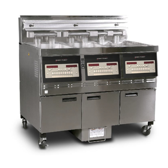
- Page 1 OPERATOR’S M A N U A L SPLIT & FULL VAT ELECTRIC OPEN FRYER MODEL KVE-071 KVE-072 KVE-073 KVE-074 REGISTER WARRANTY ONLINE AT WWW.HENNYPENN Y.COM Read instructions before operating the appliance...
- Page 3 These are the original version-controlled Henny Penny instructions for KFC Electric Low Oil Volume (KVE) 1, 2, 3 and 4 vat, model 71, 72, 73 and 74 (KVE 71, 72, 73 and 74). This manual is available on the Henny Penny Public website (www.hennypenny.com).
-
Page 5: Table Of Contents
TABLE OF CONTENTS Section Page Section 1. INTRODUCTION ................1 Introduction ................1 Proper Care ................. 1 Assistance ................... 1 Safety ..................2 Section 2. UNPACKING/INSTALLATION .............. 4 Introduction ................4 Unpacking Instructions ............... 4 Selecting the Fryer Location ............5 Leveling the Fryer .............. - Page 6 TABLE OF CONTENTS (Continued) Section Page Section 4. LEVEL 1 PROGRAMMING ............31 4-1 Modifying Product Settings ............31 4-2 AIF Clock .................. 33 4-3 Deep Clean Mode ..............34 4-4 Fryer Setup ................38 Section 5. LEVEL 2 PROGRAMMING ............39 5-1 Advanced Product Settings ............
-
Page 7: Introduction
SECTION 1: INTRODUCTION The Henny Penny open fryer is a basic unit of food processing equip- ment. This unit is used only in institutional and commercial food INTRODUCTION service operations. PROPER CARE As of August 16, 2005, the Waste Electrical and Electronic Equipment direc- tive went into effect for the European Union. -
Page 8: Safety
The instructions in this manual have been prepared to aid you in learning the proper procedures for your equipment. Where information is of SAFETY particular importance or is safety related, the words NOTICE, CAUTION, or WARNING are used. Their usage is described below. If a problem occurs during the first operation of a new unit, recheck the Installation Section of the Operator’s Manual. - Page 9 SAFETY (CONT.) Equipotential Ground Symbol Waste Electrical and Electronic Equipment (WEEE) Symbol Shock Hazard Symbols Hot Surface Symbols Shows direction to turn the red handle to open the drain valve to drain oil from vat Shows direction to turn the yellow handle to open the fill valve to pump oil into vat July 2014...
-
Page 10: Unpacking/Installation
SECTION 2: UNPACKING / INSTALLATION This section provides the installation and unpacking instructions for the Henny Penny KFC, KVE fryer. Installation of this unit should be performed only by a qualified service technician. INTRODUCTION • The wrong installation and maintenance will cause the loss of equipment function and personal injury. -
Page 11: Selecting The Fryer Location
SELECTING THE FRYER LOCATION The proper location of the fryer is very important for operation, speed, and convenience. The location of the open fryer should allow clear- ances for servicing and proper operation. Choose a location which will provide easy loading and unloading without interfering with the final assembly of food orders. -
Page 12: Ventilation Of Fryer
The fryer should be located with provision for venting into adequate exhaust hood or ventilation system. This is essential to permit efficient VENTILATION OF removal of steam exhaust and frying odors. Special precaution must FRYER be taken in designing an exhaust canopy to avoid interference with the operation of the fryer. - Page 13 An all pole, separate disconnect switch, with proper capacity fuses or ELECTRICAL breakers must be installed at a convenient location between the fryer REQUIREMENTS and the power source, and must be installed according to national and (CONT.) local codes. It is recommended that a 30 mA rated protective device such as a re- sidual current circuit breaker (RCCB), or ground fault circuit interrupter (GFCI), be used on the fryer circuit.
-
Page 14: Dimensions
2-9a DIMENSIONS Casters adjustable up to 1.562 in (40mm) July 2014... - Page 15 2-9b DIMENSIONS Single Well Model 071 Dimensions: Install: Width 17.08 in. (434 mm) Depth 33.13 in. (842 mm) Height 46.425 in. (1180 mm) Adjustable Up .800 in. (20 mm) Weight 243 lbs. (110 kg.) Crated: Width 21.70 in. (551 mm) Depth 36.13 in.
-
Page 16: Operation
SECTION 3: OPERATION 3-1. OPERATING COMPONENTS Figure 3-1 Figure 3-2 July 2014... - Page 17 Refer to Figures 3-1 & 3-2 in conjunction with the description of the functions below. OPERATING COMPONENTS (CONT.) Fig. Item Description Function This LED lights when the control calls for heat for the left vat(s), and the elements come on and heat the oil During normal operation, press this button to start and stop cook cycles for the left basket;...
- Page 18 OPERATING COMPONENTS (CONT.) Fig. No. Item No. Description Function 11 & 14 Used in the Programming and Filtering Modes; also used for ◄ or ► buttons; press to view the following filtering stats : a. the number of cook cycles before next filter b.
- Page 19 RIGHT-HAND SPLIT VATS To compensate for spacing issues, the drain and return valve handles are located differently for fryers with split vats on the far right-hand side of the fryer. See photo below. Figure 3-4 Fig. Item Description Function Oil is drained into this pan and then is pumped through filters to Filter Drain Pan Assy.
-
Page 20: Set-Up Mode
SET-UP MODE Upon initial start-up, the controls will ask to confirm the settings for the fryer. When the main power switch is turned on, “OFF” shows in both dis- plays. Press on either side and *SETUP* *MODE* shows in the displays, followed by, “LANGUAGE”... -
Page 21: Filling Or Adding Oil
FILLING OR ADDING OIL The oil level must always be above the heating elements when the fryer is heating and at the oil level indicators on the rear of the vat. Failure to follow these instructions could result in a fire and/or damage to the fryer. Solid oil is not recommended and could cause clogging and pump failures. -
Page 22: Morning Start-Up Procedures
Make sure vat is filled with oil to the proper level. MORNING START-UP Move power switch to the ON position and then press to turn PROCEDURES on heat for the desired vat. If display shows “IS POT FILLED?” make sure oil is at the proper level (see Section 3-3) and then press button for “YES”. -
Page 23: Cooking With Dedicated Display
A dedicated display means, one product always shows in the display of a particular vat. COOKING WITH DEDICATED DISPLAY Once out of the Melt Cycle, LOW TEMP flashes until the setpoint temperature has been reached. No cook cycles can be started while “LOW TEMP”... -
Page 24: Cooking With Multi-Product Display
A multi-product display means, a product must be selected before start- COOKING WITH ing a cook cycle in a particular vat. MULTI-PRODUCT DISPLAY Once out of the Melt Cycle, LOW TEMP flashes until the setpoint temperature has been reached. Then the display shows “ -------- ”. Press a product button, for ex: and product now can be placed in the oil. -
Page 25: Change From Multi-Product Display To Dedicated Display
The display shows “ -------- ” if in the Multi-Product Display Mode and CHANGE FROM can be changed to a dedicated dis play MULTIPRODUCT Press a product button, for ex: DISPLAY TO A DEDICATED DISPLAY The display shows “FR FRIES” if the set-point of the vat matches the product, or the display shows “<<<<... -
Page 26: Quick Filter
Press and hold (on either side) until display shows “1.QUICK 3-11 FILTER?” “YES NO”. If filtering is not desired, press X button and fryer QUICK FILTER resumes normal operation. Check Filter Pan: If filtering is desired, press button for √ YES and display shows “DRAIN PAN READY?”... - Page 27 NO”. Make sure vat is full and then press button. √ July 2014...
- Page 28 3-11. QUICK FILTER Display shows “CLOSE RETURN VALVE” followed by (CONT.) “CONFIRM”. Allow oil to bubble for 10 to 15 seconds and then close the yellow return valve handle. Press button √ PURGE VALVE HANDLE and the control returns to normal operation. NOTE: Purge valves are available on select units for solid shortening.
-
Page 29: Maintenance Filter
3-12 MAINTENANCE FILTER Put on protective gear: Be sure to use all approved safety equipment (ONCE A DAY) including, apron, face shield and gloves. Never begin filter-ing until you’re wearing all safety gear. Hot oil can cause severe burns. Check Filter Pan: A new filter pad should be used on the first filter of each day, but the same filter pad can be used the rest of the day, except for fish vats. - Page 30 3-12 MAINTENANCE FILTER Avoid putting the lift tool in the center of the elements, at the same area as the high (CONT.) limit bulb, or damage to the high limit could result. PURGE VALVE HANDLE Use scouring tool, nylon scouring pad, and small amount of Fryer Cleanser to scrub inside of vat.
-
Page 31: Discarding Oil From Vat Using Oil Discard Shuttle
Once full, the display shows “IS POT FILLED” “YES NO”. Press 3-12 √ button and display shows “CLOSE RETURN VALVE” , followed by MAINTENANCE “CONFIRM”. FILTER (CONT.) Turn the yellow return handle to close valve, press √ button. Display shows “OPEN BLACK PURGE HANDLE” followed by “CONFIRM”. -
Page 32: Changing The Filter Pad
In order to assure good oil pumping performance, the filter pad (or 3-14 paper) should be changed and the filter pan cleaned at least once per day. CHANGING THE FILTER PAD However, in stores open 24 hours a day, the pad should be changed twice a day. - Page 33 3-14 CHANGING THE FILTER PAD (CONT.) Pull the filter pad from the pan and discard pad. Figure 5. Figure 5 Remove the bottom screen from pan and clean thoroughly with soap and water. Rinse thoroughly with hot water. Figure 6. Figure 6 Wipe the oil and crumbs from the drain pan.
-
Page 34: Removing And Cleaning Basket Rest
3-14 CHANGING THE Clean the drain pan with soap and water, then thoroughly rinse FILTER PAD with hot water. Be sure that the drain pan, bottom screen, crumb catcher, and the retaining ring are thoroughly dry (CONT.) before placing filter pad into pan as water will dissolve the filter pad. -
Page 35: Info Button Stats
Recovery Information for each Vat 3-16. Press and release and REC shows in the left display and INFO BUTTON the recovery time that oil temperature went from 250°F (121°C) STATS to 300°F (149°C) shows in the right display. For example, 1:05 means it took 1 minute and 5 seconds for the oil temperature to recover to 300°F (149°C) from 250°F (121°C). -
Page 36: Information Mode
This mode gathers and stores historic information on the fryer and op- 3-19 erator’s performance. Press and hold for 3 seconds, until *INFO* INFORMATION *MODE*” shows on the displays. MODE Press ▲ or ▼ buttons to access the steps and press button to view the √... - Page 37 LAST LOAD 3-19 Press button to select Last Load (ex: -P1- = Product 1; INFORMATION √ ”L1” = left, 1st product) and press ▲ or ▼ buttons to view the follow- MODE ing: (CONT.) FUNCTION DISPLAY EX. Product (Last product cooked) PRODUCT P1- L1 Time and day last Cook Cycle was started...
-
Page 38: Level 1 Programming
SECTION 4: LEVEL 1 PROGRAMMING Level 1 contains the following: • Modify product settings MODIFYING • AIF clock (Blocks “FILTER NOW” prompts) PRODUCT SETTINGS • Perform the Deep Clean procedure • Fryer Setup Mode Press and hold buttons until LEVEL - 1 shows in the display, followed by ENTER CODE. - Page 39 Press and release ▼ button and “TEMP” shows in display, along with preset temperature on the right side of the display. MODIFYING PRODUCT SETTINGS Press the product buttons to change (CONT.) the temperature. The temperature range is 190°F (88°C) to 380°F (193°C).
-
Page 40: Aif Clock
This feature allows the controls to be set for periods of the day that block the automatic “Filter Now” prompts. For example, the controls 4-2. could be set to not interrupt with “Filter Now” prompts during the lunch AIF CLOCK rush, and during the supper rush. -
Page 41: Deep Clean Mode
In 12-hour clock mode, there are three items on each line: the start time 4-2. “XX:XX”, the A or P (am/pm) setting, and the “XX” duration. Use the ◄ AIF CLOCK and ► buttons to set these items, which flashes when the item is selected. (CONT.) To set a new start time setting, use the product buttons , to enter the new value. - Page 42 Split vat fryers only! Display shows “LEFT RGHT”, asking you to select which vat will be cleaned. Press button to select left vat, or √ DEEP CLEAN MODE X button for the right vat. (CONT.) Display shows “OIL RMVD” “YES NO” If oil has already been removed, press button and control skips √...
- Page 43 Using a 1/2 gal. (2 liter) pitcher, remove solution from vat, pouring it into a heat-resistant bucket for disposal. Any remaining solution DEEP CLEAN MODE can be drained into the drain pan for disposal, in step 14 below. (CONT.) Press button and display shows “VAT EMTY”...
- Page 44 16. Pour clean water into vat to rinse vat and allow rinse water to drain into drain pan. Rinse at least 3 times but be careful not to overfill DEEP CLEAN MODE the drain pan. Display now shows “RINSE COMPLETE” “YES (CONT.) NO”.
-
Page 45: Fryer Setup
This mode has the same settings as seen upon initial start-up of the fryer. See Setup Mode, Section 3-3. FRYER SETUP Press and hold buttons until LEVEL - 1 shows in the display, followed by ENTER CODE. Enter code 1, 2, 3, 4 (first 4 product buttons). “PRODUCT” and “SELECTN”... -
Page 46: Level 2 Programming
SECTION 5: LEVEL 2 PROGRAMMING Used to access the following: • Advanced changes to product settings • Error code log ADVANCED PRODUCT • Password programming SETTINGS • Alert Tone/Volume • No. of cook cycles before filter is suggested • Automatic filter time Press hold and buttons until LEVEL - 2 shows in the display, followed by ENTER CODE. -
Page 47: E-Log (Error Code Log)
Press ▼ button until “FULL HT” shows in the display along with the full heat value in seconds, which means the heat is on as soon as ADVANCED PRODUCT a timer button is pressed, for the programmed length of time. Press SETTINGS the product buttons to change this... -
Page 48: Password
The 4-digit passwords can be changed for access to Set-Up, Usage, Level 1, Level 2, & Get Mgr.) PASSWORD Press and hold buttons until LEVEL - 2 shows in the display, followed by ENTER CODE. Enter code 1, 2, 3, 4 (first 4 product buttons). “PROD” and “COMP”... -
Page 49: Filter After
This is the number of cook cycles between filters. FILTER AFTER Press and hold buttons until LEVEL - 2 shows in the display, followed by ENTER CODE. Enter code 1, 2, 3, 4 (first 4 product buttons). “PROD” and “COMP” show in the displays. Press ▼... -
Page 50: Level 3 Programming
SECTION 6: LEVEL 3 PROGRAMMING 1. Press and hold the TEMP and INFO buttons at the same KVE SPECIAL time until level 3 is displayed, enter password 11221122, and enter 3 levels of programming. 2. Use the UP/DWN button loop menu to select Special Programming. -
Page 51: Troubleshooting
SECTION 7: TROUBLESHOOTING TROUBLE SHOOTING GUIDE Problem Cause Correction • Open circuit • Plug fryer in POWER switch ON but fryer completely • Check breaker or fuse at supply box inoperative • (Non-US/some Int’l. locations only) Breakers in fryer tripped-open left door and reset breaker on fryer;... - Page 52 TROUBLE SHOOTING GUIDE (CONT.) Problem Cause Correction Oil foaming or boiling • Water in oil • Drain and clean oil over top of vat • Improper or bad oil • Use recommended oil • Improper filtering • Refer to filtering procedures •...
-
Page 53: Error Codes
In the event of a control system failure, the digital display shows an error message. The message codes are shown in the DISPLAY column below. A constant tone is heard when an error code is displayed, and to silence this ERROR CODES tone, press any button. - Page 54 ERROR CODES DISPLAY CAUSE CORRECTION “E-22” Heat Error-No Heat Check power cord and have heat circuit checked “E-31” Elements are up Lower elements back into the vat “E-41”, Programming failure Turn switch to OFF, then back to ON; if display shows any “E-46”...
- Page 56 Henny Penny Corporation P.O.Box 60 Eaton,OH 45320 1-937-456-8400 1-937-456-8402 Fax Toll free in USA 1-800-417-8417 1-800-417-8434 Fax www.hennypenny.com *FM05-257-A Henny Penny Corp., Eaton, Ohio 45320, Revised 11-11-20...