
Related Manuals for Nokia RM-291


Summary of Contents for Nokia RM-291
- Page 1 Nokia Customer Care Service Manual RM-291 (Nokia 2626) Mobile Terminal Part No: 9254426 (Issue 1) COMPANY CONFIDENTIAL Copyright © 2007 Nokia. All rights reserved.
- Page 2 RM-291 Nokia Customer Care Amendment Record Sheet Amendment Record Sheet Amendment No Date Inserted By Comments Original issue 1/2007 Y Liu Page ii COMPANY CONFIDENTIAL Issue 1 Copyright © 2007 Nokia. All rights reserved.
- Page 3 Nokia operates a policy of continuous development. Nokia reserves the right to make changes and improvements to any of the products described in this document without prior notice. Under no circumstances shall Nokia be responsible for any loss of data or income or any special, incidental, consequential or indirect damages howsoever caused.
- Page 4 WCDMA networks and cause problems to 3G cellular phone communication in a wide area. • During testing never activate the GSM or WCDMA transmitter without a proper antenna load, otherwise GSM or WCDMA PA may be damaged. Page iv COMPANY CONFIDENTIAL Issue 1 Copyright © 2007 Nokia. All rights reserved.
- Page 5 Use only approved accessories and batteries. Do not connect incompatible products. CONNECTING TO OTHER DEVICES When connecting to any other device, read its user’s guide for detailed safety instructions. Do not connect incompatible products. Issue 1 COMPANY CONFIDENTIAL Page v Copyright © 2007 Nokia. All rights reserved.
- Page 6 All of the above suggestions apply equally to the product, battery, charger or any accessory. Page vi COMPANY CONFIDENTIAL Issue 1 Copyright © 2007 Nokia. All rights reserved.
- Page 7 Nokia Customer Care ESD protection Nokia requires that service points have sufficient ESD protection (against static electricity) when servicing the phone. Any product of which the covers are removed must be handled with ESD protection. The SIM card can be replaced without ESD protection if the product is otherwise ready for use.
- Page 8 Batteries' performance is particularly limited in temperatures well below freezing. Do not dispose of batteries in a fire! Dispose of batteries according to local regulations (e.g. recycling). Do not dispose as household waste. Page viii COMPANY CONFIDENTIAL Issue 1 Copyright © 2007 Nokia. All rights reserved.
- Page 9 Our policy is of continuous development; details of all technical modifications will be included with service bulletins. While every endeavour has been made to ensure the accuracy of this document, some errors may exist. If any errors are found by the reader, NOKIA MOBILE PHONES Business Group should be notified in writing/e- mail. Please state: •...
- Page 10 RM-291 Nokia Customer Care Company Policy (This page left intentionally blank.) Page x COMPANY CONFIDENTIAL Issue 1 Copyright © 2007 Nokia. All rights reserved.
- Page 11 2 Parts and layouts 3 Phoenix service SW 4 Service Tools 5 Disassembly and reassembly instructions 6 Baseband troubleshooting 7 RF troubleshooting 8 System module 9 Schematics Glossary Issue 1 COMPANY CONFIDENTIAL Page xi Copyright © 2007 Nokia. All rights reserved.
- Page 12 RM-291 Nokia Customer Care Nokia 2626 Service Manual Structure (This page left intentionally blank.) Page xii COMPANY CONFIDENTIAL Issue 1 Copyright © 2007 Nokia. All rights reserved.
- Page 13 Nokia Customer Care 1 — General information Issue 1 COMPANY CONFIDENTIAL Page 1 –1 Copyright © 2007 Nokia. All rights reserved.
- Page 14 RM-291 Nokia Customer Care General information (This page left intentionally blank.) Page 1 –2 COMPANY CONFIDENTIAL Issue 1 Copyright © 2007 Nokia. All rights reserved.
-
Page 15: Table Of Contents
Table 3 Audio ................................1–7 Table 4 Carrying..............................1–7 Table 5 Normal and extreme voltages .........................1–8 Table 6 Current consumption..........................1–9 List of Figures Figure 1 RM-291 product picture ..........................1–5 Issue 1 COMPANY CONFIDENTIAL Page 1 –3 Copyright © 2007 Nokia. All rights reserved. - Page 16 RM-291 Nokia Customer Care General information (This page left intentionally blank.) Page 1 –4 COMPANY CONFIDENTIAL Issue 1 Copyright © 2007 Nokia. All rights reserved.
-
Page 17: Product Selection
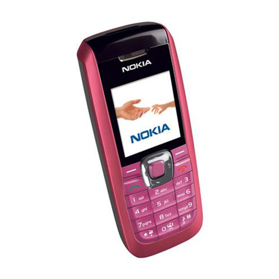
RM-291 General information Nokia Customer Care Product selection The RM-291 is the EU version of the telephone with a dual band transceiver unit designed for the GSM900 and GSM1800 networks. Figure 1 RM-291 product picture Features Phone features Display and keypad •... -
Page 18: Software And User Interface Features
Battery 970 mAh Li-Ion AC-1 Retractable charger ACP-12E/ACP-12X Travel charger LCH-12 Mobile charger Table 2 Car Type Name BHF-2 Headrest hands free CK-10 Nokia car kit Page 1 –6 COMPANY CONFIDENTIAL Issue 1 Copyright © 2007 Nokia. All rights reserved. -
Page 19: Technical Specifications
Variation in operation times will occur depending on SIM card, network settings and usage. Talk time is increased by up to 30% if half rate is active and reduced by 5% if enhanced full rate is active. Issue 1 COMPANY CONFIDENTIAL Page 1 –7 Copyright © 2007 Nokia. All rights reserved. -
Page 20: Environmental Conditions
SW shutdown voltages SW shutdown 3. 1V In call SW shutdown 3. 2V In idle Min operating voltage Vcoff+ 3. 1V ± 0,1V Off to on Page 1 –8 COMPANY CONFIDENTIAL Issue 1 Copyright © 2007 Nokia. All rights reserved. -
Page 21: Table 6 Current Consumption
The minimum battery cell voltage required for the reset circuitry to turn on. This is not confirmed by measures at pt. Table 6 Current consumption Condition Typical Unit Call (MoU) (E)GSM 900 GSM 1800 Idle (MoU) 2.72 Power off µA Issue 1 COMPANY CONFIDENTIAL Page 1 –9 Copyright © 2007 Nokia. All rights reserved. - Page 22 RM-291 Nokia Customer Care General information (This page left intentionally blank.) Page 1 –10 COMPANY CONFIDENTIAL Issue 1 Copyright © 2007 Nokia. All rights reserved.
- Page 23 Nokia Customer Care 2 — Parts and layouts Issue 1 COMPANY CONFIDENTIAL Page 2 –1 Copyright © 2007 Nokia. All rights reserved.
- Page 24 RM-291 Nokia Customer Care Parts and layouts (This page left intentionally blank.) Page 2 –2 COMPANY CONFIDENTIAL Issue 1 Copyright © 2007 Nokia. All rights reserved.
-
Page 25: Table Of Contents
Table 8 SWAP units..............................2–7 Table 9 Changeable components..........................2–7 List of Figures Figure 2 Component layout, top side (1vj_52e) ....................2–14 Figure 3 Component layout, bottom side (1vj_52e) ..................2–15 Issue 1 COMPANY CONFIDENTIAL Page 2 –3 Copyright © 2007 Nokia. All rights reserved. - Page 26 RM-291 Nokia Customer Care Parts and layouts (This page left intentionally blank.) Page 2 –4 COMPANY CONFIDENTIAL Issue 1 Copyright © 2007 Nokia. All rights reserved.
- Page 27 RM-291 Parts and layouts Nokia Customer Care Exploded view Mechanical parts list Table 7 Mechanical spare parts Issue 1 COMPANY CONFIDENTIAL Page 2 –5 Copyright © 2007 Nokia. All rights reserved.
- Page 28 CONN SYST TWIN JACK+FLASH CONN/4P Antenna Module SAM P3291 EU I017* Antenna I018* I020 B-Cover Paint RED I020 B-Cover Paint SKY BLUE I020 B-Cover Paint WHITE Page 2 –6 COMPANY CONFIDENTIAL Issue 1 Copyright © 2007 Nokia. All rights reserved.
- Page 29 Chipcap X7R 10% 16V 0402 C2009 Chipcap X7R 10% 16V 0402 C2010 Chipcap X7R 10% 16V 0402 C2011 CHIPCAP X5R 1U K 6V3 0603 C2012 Chipcap X7R 10% 16V 0402 Issue 1 COMPANY CONFIDENTIAL Page 2 –7 Copyright © 2007 Nokia. All rights reserved.
- Page 30 CHIPCAP X5R 1U K 6V3 0603 C2236 CHIPCAP X5R 100N K 10V 0402 C2237 CHIPCAP X5R 100N K 10V 0402 C2239 CHIPCAP X5R 100N K 10V 0402 Page 2 –8 COMPANY CONFIDENTIAL Issue 1 Copyright © 2007 Nokia. All rights reserved.
- Page 31 CHIPCAP NP0 0P5 C 50V 0402 C7606 Chipres 0W06 jumper 0402 C7606 Chipcap +-0.25pF NP0 C7607 Chipcap +-0.25pF NP0 C7610 Chipcap 5% NP0 C7611 Chipcap 5% NP0 C7612 Chipcap 5% NP0 Issue 1 COMPANY CONFIDENTIAL Page 2 –9 Copyright © 2007 Nokia. All rights reserved.
- Page 32 Chipcap 5% NP0 C7702 Chipcap 5% NP0 C7711 CHIPCAP X5R 2U2 K 10V 0805 C7712 Chipcap +-0.25pF NP0 C7712 Chipcap 5% NP0 C7713 Chipcap 5% NP0 Page 2 –10 COMPANY CONFIDENTIAL Issue 1 Copyright © 2007 Nokia. All rights reserved.
- Page 33 DC/DC CONV LM3500/ TK65600 USMD8 N7600 HUGIN + PMB3258V1.1 B9C PGVGFN48-4/-6 N7700 FEM PF88112BS_12WS0 2B-TX 2B-RX N7700 FEM PF88112BS_12WS0 2B-TX 2B-RX R2000 CHIP VARISTOR VWM5.6V VC15.5 0402 Issue 1 COMPANY CONFIDENTIAL Page 2 –11 Copyright © 2007 Nokia. All rights reserved.
- Page 34 Resistor 5% 63mW R2200 CHIPRES 0W25 0R22 J 0805 R2202 Resistor 5% 63mW R2203 Resistor 5% 63mW R2204 Resistor 5% 63mW R2205 RES NETWORK 0W06 2X10K J 0404 Page 2 –12 COMPANY CONFIDENTIAL Issue 1 Copyright © 2007 Nokia. All rights reserved.
- Page 35 R7704 Resistor 5% 63mW R7705 Resistor 5% 63mW R7706 Resistor 5% 63mW R7707 Resistor 5% 63mW R7709 Chipres 0W06 jumper 0402 R7710 Chipres 0W06 jumper 0402 Issue 1 COMPANY CONFIDENTIAL Page 2 –13 Copyright © 2007 Nokia. All rights reserved.
- Page 36 SAW 942.5+-17.5MHZ 2.0X1.6 Z7602 SAW 942.5+-17.5MHZ 2.0X1.6 Z7603 SILICON FILT 869.5+-45.5MHZ P-TSLP-7-4 Z7604 SILICON FILT 1810+-100MHZ P-TSLP-7-4 Component layouts Figure 2 Component layout, top side (1vj_52e) Page 2 –14 COMPANY CONFIDENTIAL Issue 1 Copyright © 2007 Nokia. All rights reserved.
- Page 37 RM-291 Parts and layouts Nokia Customer Care Figure 3 Component layout, bottom side (1vj_52e) Issue 1 COMPANY CONFIDENTIAL Page 2 –15 Copyright © 2007 Nokia. All rights reserved.
- Page 38 RM-291 Nokia Customer Care Parts and layouts (This page left intentionally blank.) Page 2 –16 COMPANY CONFIDENTIAL Issue 1 Copyright © 2007 Nokia. All rights reserved.
- Page 39 Nokia Customer Care 3 — Phoenix service SW Issue 1 COMPANY CONFIDENTIAL Page 3 –1 Copyright © 2007 Nokia. All rights reserved.
- Page 40 RM-291 Nokia Customer Care Phoenix service SW (This page left intentionally blank.) Page 3 –2 COMPANY CONFIDENTIAL Issue 1 Copyright © 2007 Nokia. All rights reserved.
- Page 41 Figure 28 Finish data package installation....................... 3–21 Figure 29 Uninstalling Phoenix data package....................3–22 Figure 30 Finish data package uninstallation ....................3–22 Figure 31 Login..............................3–23 Issue 1 COMPANY CONFIDENTIAL Page 3 –3 Copyright © 2007 Nokia. All rights reserved.
- Page 42 Figure 67 Checking JBV-1 SW version ........................ 3–40 Figure 68 JBV-1 update directory window......................3–40 Figure 69 JBV-1 SW update done ........................3–41 Figure 70 JBV-1 SW status........................... 3–41 Page 3 –4 COMPANY CONFIDENTIAL Issue 1 Copyright © 2007 Nokia. All rights reserved.
-
Page 43: Introduction
• Minimum: Processor 300 MHz, RAM memory 64 MB, disk space 100 MB. • Recommended for Windows 2000: Processor 700 MHz, RAM memory 256 MB, disk space 150 MB. Issue 1 COMPANY CONFIDENTIAL Page 3 –5 Copyright © 2007 Nokia. All rights reserved. -
Page 44: Installing Phoenix
For more detailed information, please refer to Phoenix Help files. Each feature in Phoenix has its own Help function, which can be activated while running the program. Press the F1 key or the Help button to activate a Help file. Page 3 –6 COMPANY CONFIDENTIAL Issue 1 Copyright © 2007 Nokia. All rights reserved. - Page 45 Phoenix service SW Nokia Customer Care Steps phoenix_service_sw_a15_2004_24_7_55.exe to start installation. Install Shield prepared the setup. 1. Run the Figure 5 Preparing setup Install Shield will prepare. Issue 1 COMPANY CONFIDENTIAL Page 3 –7 Copyright © 2007 Nokia. All rights reserved.
- Page 46 Nokia Customer Care Phoenix service SW 2. Click Next in Welcome dialog to continue. Figure 6 Welcome dialog 3. Read the disclaimer carefully. Figure 7 Disclaimer text Page 3 –8 COMPANY CONFIDENTIAL Issue 1 Copyright © 2007 Nokia. All rights reserved.
- Page 47 Figure 8 Destination folder Setup Status window. 5. Wait for the components to be copied. The progress of the setup is shown in the Figure 9 Installation status 1 Issue 1 COMPANY CONFIDENTIAL Page 3 –9 Copyright © 2007 Nokia. All rights reserved.
- Page 48 If the operating system does not require rebooting (Windows 2000, XP) the PC components are registered right away. Figure 10 Installation status 2 Figure 11 Registering components 1 Page 3 –10 COMPANY CONFIDENTIAL Issue 1 Copyright © 2007 Nokia. All rights reserved.
- Page 49 After the reboot, components are registered and Phoenix is ready for use. Note: Phoenix does not work, if components have not been registered. Figure 13 Registering components 2 Issue 1 COMPANY CONFIDENTIAL Page 3 –11 Copyright © 2007 Nokia. All rights reserved.
-
Page 50: Phoenix Update Installation
• Driver versions will be checked and updated. When you update Phoenix from old to new version (for example, a14_2004_16_4_47 to a15_2004_24_7_55), the update will take place automatically without uninstallation. Page 3 –12 COMPANY CONFIDENTIAL Issue 1 Copyright © 2007 Nokia. All rights reserved. -
Page 51: Uninstalling Phoenix
Uninstalling Phoenix Context Uninstallation can be done manually from Windows Control Panel→Add/Remove Programs . Steps 1. Choose Phoenix Service Software→Add/Remove→Remove to uninstall Phoenix. Figure 16 Remove program Issue 1 COMPANY CONFIDENTIAL Page 3 –13 Copyright © 2007 Nokia. All rights reserved. - Page 52 Else, Install Shield Wizard will tell you about it. Select Yes... to reboot the PC immediately and No... to reboot the PC manually afterwards. Figure 18 Finish uninstallation Page 3 –14 COMPANY CONFIDENTIAL Issue 1 Copyright © 2007 Nokia. All rights reserved.
-
Page 53: Repairing Phoenix Installation
2. Select Phoenix Service Software→Add/Remove . 3. In the following view, choose Repair. Phoenix will now reinstall components and register them. The procedure is the same as in the update installation. Issue 1 COMPANY CONFIDENTIAL Page 3 –15 Copyright © 2007 Nokia. All rights reserved. - Page 54 RM-291 Nokia Customer Care Phoenix service SW Figure 20 Repair program 4. Click Finish to complete repair. Figure 21 Finish repair installation Page 3 –16 COMPANY CONFIDENTIAL Issue 1 Copyright © 2007 Nokia. All rights reserved.
-
Page 55: Phoenix Service Software Data Package Overview
• Files for type label printing • Validation file for the faultlog repair data reporting system • All product-specific configuration files for Phoenix Service Software components Data files are stored under C:\Program Files\Nokia\Phoenix (default). Installing Phoenix data package Prerequisites 1 Verify that The data package contains all product-specific data to make the Phoenix Service Software and tools usable with a certain phone model. - Page 56 2. Click Next, and wait for the installation files to be extracted. Figure 22 Extracting files 3. Click Next to continue. Figure 23 Continue data package installation Page 3 –18 COMPANY CONFIDENTIAL Issue 1 Copyright © 2007 Nokia. All rights reserved.
- Page 57 Phoenix version required with this data package. Click Next to continue. Figure 24 Data package setup information 4. Confirm location and click Next to continue. Figure 25 Data package destination folder Issue 1 COMPANY CONFIDENTIAL Page 3 –19 Copyright © 2007 Nokia. All rights reserved.
- Page 58 Click Next to continue. 5. Click Next to start copying the files. Phone model specific files will be installed. Please wait. Figure 26 Start copying files Page 3 –20 COMPANY CONFIDENTIAL Issue 1 Copyright © 2007 Nokia. All rights reserved.
- Page 59 6. Click Finish to complete the installation. Figure 28 Finish data package installation You now have all phone model specific files installed in your Phoenix Service SW. Issue 1 COMPANY CONFIDENTIAL Page 3 –21 Copyright © 2007 Nokia. All rights reserved.
-
Page 60: Uninstalling Phoenix Data Package
1. Click OK to uninstall, Cancel if you don’t want to uninstall. Figure 29 Uninstalling Phoenix data package 2. Once the previously installed data package is uninstalled, click Finish. Figure 30 Finish data package uninstallation Page 3 –22 COMPANY CONFIDENTIAL Issue 1 Copyright © 2007 Nokia. All rights reserved. -
Page 61: Service Software Instructions
Maintain. Figure 31 Login 2. Choose New to add information for a new user. Figure 32 Add information for new user 1 Issue 1 COMPANY CONFIDENTIAL Page 3 –23 Copyright © 2007 Nokia. All rights reserved. -
Page 62: Managing Connections In Phoenix
You are now able to login with this user name. 5. Click OK. Figure 34 Login, user configured Managing connections in Phoenix Steps Phoenix Service SW and log in. 1. Start Figure 35 Phoenix icon Page 3 –24 COMPANY CONFIDENTIAL Issue 1 Copyright © 2007 Nokia. All rights reserved. - Page 63 In the following dialogs you will be asked to select settings for the connection. If you use the Wizard, connect the tools and a phone to your PC and the wizard will automatically try to configure the correct connection. Issue 1 COMPANY CONFIDENTIAL Page 3 –25 Copyright © 2007 Nokia. All rights reserved.
- Page 64 For FPS-8 Flash Prommer, choose the following connection settings: • Media: FPS-8 • Port Num: COM Port where FPS-8 is connected • COMBOX_DEF_MEDIA: FBUS 5. Click Finish to complete the configuration. Page 3 –26 COMPANY CONFIDENTIAL Issue 1 Copyright © 2007 Nokia. All rights reserved.
- Page 65 When a product is found, Phoenix will load product support. Name of the loaded product support module and its version information will be shown on the bottom of the screen. Issue 1 COMPANY CONFIDENTIAL Page 3 –27 Copyright © 2007 Nokia. All rights reserved.
-
Page 66: Installing Flash Support Files For Fps-8* And Fls-4
SW update (page 3–32) after installing a new phone data package. Steps flash_update_03_13_001.exe to begin installation. 1. Start by double clicking Figure 44 Flash update welcome dialog Page 3 –28 COMPANY CONFIDENTIAL Issue 1 Copyright © 2007 Nokia. All rights reserved. - Page 67 Figure 46 Flash installation interrupted If an older version exists on your PC and it needs to be updated, click Next to continue installation. Figure 47 Continue flash update Issue 1 COMPANY CONFIDENTIAL Page 3 –29 Copyright © 2007 Nokia. All rights reserved.
- Page 68 When installing the flash update files for the first time you may choose another location by selecting Browse. However, this is not recommended. Installation will continue. Page 3 –30 COMPANY CONFIDENTIAL Issue 1 Copyright © 2007 Nokia. All rights reserved.
- Page 69 4. Choose Finish to complete the installation procedure. Figure 50 Finish flash update Next actions FLS-4 can be used right after the Flash Update Package is installed. Issue 1 COMPANY CONFIDENTIAL Page 3 –31 Copyright © 2007 Nokia. All rights reserved.
-
Page 70: Updating Fps-8 Flash Prommer Software
3. When the new FPS-8 flash update package is installed to computer you will be asked to update the files to your FPS-8 Prommer. Select Yes to update files. Figure 53 Prommer SW update Page 3 –32 COMPANY CONFIDENTIAL Issue 1 Copyright © 2007 Nokia. All rights reserved. - Page 71 4. Wait until you are notified that update has been successful; the procedure will take a couple of minutes. FPS-8 Maintenance window. Click OK to close the Figure 54 Prommer SW update done View after successful prommer software update: Figure 55 FPS-8 info window Issue 1 COMPANY CONFIDENTIAL Page 3 –33 Copyright © 2007 Nokia. All rights reserved.
-
Page 72: Activating Fps-8
\BoxActivation directory on your computer (this directory is created when Phoenix is installed). Steps Phoenix Service Software . 1. Start 2. Select Flashing→FPS-8 maintenance . Figure 57 FPS-8 maintenance Page 3 –34 COMPANY CONFIDENTIAL Issue 1 Copyright © 2007 Nokia. All rights reserved. -
Page 73: Deactivating Fps-8
If there is, for example, a need to send the FPS-8 box for repair, it must be deactivated first. Steps Phoenix service software. 1. Start 2. Choose Flashing→Prommer Maintenance . Issue 1 COMPANY CONFIDENTIAL Page 3 –35 Copyright © 2007 Nokia. All rights reserved. -
Page 74: Updating Jbv-1 Docking Station Software
Steps Jbv1_18_update.zip file and start software installation by double clicking Setup.exe . Note: DO NOT CONNECT THE USB CABLE/JBV-1 TO YOUR COMPUTER YET! Page 3 –36 COMPANY CONFIDENTIAL Issue 1 Copyright © 2007 Nokia. All rights reserved. - Page 75 Read the instructions in the dialog box and click Next to continue. Figure 62 JBV-1 update information Accept the suggested destination folder for installing the JBV-1 SW Package, and click Next to continue. Issue 1 COMPANY CONFIDENTIAL Page 3 –37 Copyright © 2007 Nokia. All rights reserved.
- Page 76 RM-291 Nokia Customer Care Phoenix service SW Figure 63 JBV-1 update destination folder Select Full installation and click Next to continue. Figure 64 Select installation: Full Page 3 –38 COMPANY CONFIDENTIAL Issue 1 Copyright © 2007 Nokia. All rights reserved.
- Page 77 Connect the USB cable/JBV-1 to your computer. Connect power to JBV-1 (11-16V DC) from an external power supply, then connect the USB Cable between the JBV-1 USB connector and the PC. Issue 1 COMPANY CONFIDENTIAL Page 3 –39 Copyright © 2007 Nokia. All rights reserved.
- Page 78 Firmware Update\JBV-1USB driver folder for instructions on how to update the JBV-1 USB Driver. After you have installed or updated the JBV-1 USB driver, the actual JBV-1 SW update can begin. C:\Program Files\Nokia\JBV-1 Firmware Update\JBV-1 Firmware Update and start JBV-1 Go to folder fwup.exe .
- Page 79 First, click Refresh Status to see the current SW version and then Update Firmware to update the software. JBV-1 Firmware Update dialog box. After you have updated all docking stations, close the Issue 1 COMPANY CONFIDENTIAL Page 3 –41 Copyright © 2007 Nokia. All rights reserved.
- Page 80 RM-291 Nokia Customer Care Phoenix service SW (This page left intentionally blank.) Page 3 –42 COMPANY CONFIDENTIAL Issue 1 Copyright © 2007 Nokia. All rights reserved.
- Page 81 Nokia Customer Care 4 — Service Tools Issue 1 COMPANY CONFIDENTIAL Page 4 –1 Copyright © 2007 Nokia. All rights reserved.
- Page 82 RM-291 Nokia Customer Care Service Tools (This page left intentionally blank.) Page 4 –2 COMPANY CONFIDENTIAL Issue 1 Copyright © 2007 Nokia. All rights reserved.
- Page 83 4–11 SRT-6................................4–11 SS-54 ................................4–11 ST-30................................4–12 ST-32................................4–12 SX-4 .................................. 4–12 XCS-4 ................................4–12 XRF-1................................4–13 Service concepts ..............................4–13 Service concepts ............................. 4–13 Issue 1 COMPANY CONFIDENTIAL Page 4 –3 Copyright © 2007 Nokia. All rights reserved.
- Page 84 RM-291 Nokia Customer Care Service Tools (This page left intentionally blank.) Page 4 –4 COMPANY CONFIDENTIAL Issue 1 Copyright © 2007 Nokia. All rights reserved.
- Page 85 Service Tools Nokia Customer Care Service tools The table below gives a short overview of service tools that can be used for testing, error analysis and repair of product RM-291, refer to various concepts. ACF-8 Universal power supply ACF-8 universal power supply is used to power FPS-8. ACF-8 has 6V DC and 2.1A output.
- Page 86 DC cable The DC cable CA-5S is used to connect JBV-1 to the phone charger jack for ADC/VCHAR/ICHAR calibration Note: Old SCB-3 can be used as well. Page 4 –6 COMPANY CONFIDENTIAL Issue 1 Copyright © 2007 Nokia. All rights reserved.
- Page 87 The MBUS cable DAU-9S has a modular connector and is used, for example, between the PC's serial port and module jigs, flash adapters or docking station adapters. Note: Docking station adapters valid for DCT4 products. Issue 1 COMPANY CONFIDENTIAL Page 4 –7 Copyright © 2007 Nokia. All rights reserved.
- Page 88 • LAN to FBUS/Flashbus and USB conversion • Vusb output switchable by PC command FPS-10 sales package includes: • FPS-10 prommer • Power Supply with 5 country specific cords • USB cable Page 4 –8 COMPANY CONFIDENTIAL Issue 1 Copyright © 2007 Nokia. All rights reserved.
- Page 89 Power cable The PCS-1 power cable (DC) is used with a docking station, a module jig or a control unit to supply a controlled operating voltage. Issue 1 COMPANY CONFIDENTIAL Page 4 –9 Copyright © 2007 Nokia. All rights reserved.
- Page 90 RF part of the phone. The SA-41 is mounted on the docking station adapter. Note: For RF attenuation values, please refer to the Service bulletin. Page 4 –10 COMPANY CONFIDENTIAL Issue 1 Copyright © 2007 Nokia. All rights reserved.
- Page 91 SRT-6 is used to open phone covers and B-to-B connectors. SS-54 Alignment Jig Alignment jig is used to efficiently assemble the dome-sheet to the pone's PWB. The jig is made of EDS proof material. Issue 1 COMPANY CONFIDENTIAL Page 4 –11 Copyright © 2007 Nokia. All rights reserved.
- Page 92 SX-4 is also needed together with FPS-10 when DCT-4 phones are flashed. XCS-4 Modular cable XCS-4 is a shielded (one specially shielded conductor) modular cable for flashing and service purposes. Page 4 –12 COMPANY CONFIDENTIAL Issue 1 Copyright © 2007 Nokia. All rights reserved.
- Page 93 RF measurement equipment. SMA to N-Connector ca. 610mm. Attenuation for: • GSM850/900: 0.3+-0.1 dB • GSM1800/1900: 0.5+-0.1 dB • WLAN: 0.6+-0.1dB Service concepts Service concepts Easy flash concept Issue 1 COMPANY CONFIDENTIAL Page 4 –13 Copyright © 2007 Nokia. All rights reserved.
- Page 94 RM-291 Nokia Customer Care Service Tools POS flash concept Flash concept with FPS-10 Page 4 –14 COMPANY CONFIDENTIAL Issue 1 Copyright © 2007 Nokia. All rights reserved.
- Page 95 RM-291 Service Tools Nokia Customer Care JBV-1 flash concept with FPS-10 and smart card Issue 1 COMPANY CONFIDENTIAL Page 4 –15 Copyright © 2007 Nokia. All rights reserved.
- Page 96 RM-291 Nokia Customer Care Service Tools JBV-1 flash concept with FPS-10 and RF tuning Page 4 –16 COMPANY CONFIDENTIAL Issue 1 Copyright © 2007 Nokia. All rights reserved.
- Page 97 RM-291 Service Tools Nokia Customer Care Module jig testing and tuning concept Issue 1 COMPANY CONFIDENTIAL Page 4 –17 Copyright © 2007 Nokia. All rights reserved.
- Page 98 RM-291 Nokia Customer Care Service Tools (This page left intentionally blank.) Page 4 –18 COMPANY CONFIDENTIAL Issue 1 Copyright © 2007 Nokia. All rights reserved.
- Page 99 Nokia Customer Care 5 — Disassembly and reassembly instructions Issue 1 COMPANY CONFIDENTIAL Page 5 –1 Copyright © 2007 Nokia. All rights reserved.
- Page 100 RM-291 Nokia Customer Care Disassembly and reassembly instructions (This page left intentionally blank.) Page 5 –2 COMPANY CONFIDENTIAL Issue 1 Copyright © 2007 Nokia. All rights reserved.
- Page 101 RM-291 Disassembly and reassembly instructions Nokia Customer Care Table of Contents Disassembly instructions ............................5–5 Reassembly instructions............................. 5–10 Issue 1 COMPANY CONFIDENTIAL Page 5 –3 Copyright © 2007 Nokia. All rights reserved.
- Page 102 RM-291 Nokia Customer Care Disassembly and reassembly instructions (This page left intentionally blank.) Page 5 –4 COMPANY CONFIDENTIAL Issue 1 Copyright © 2007 Nokia. All rights reserved.
- Page 103 RM-291 Disassembly and reassembly instructions Nokia Customer Care Disassembly instructions Steps You will need these tools: Protect the window with a film. Remove the B-cover. Issue 1 COMPANY CONFIDENTIAL Page 5 –5 Copyright © 2007 Nokia. All rights reserved.
- Page 104 Unscrew the six Torx Plus size 6 screws in the shown order. Note: For assembly, use the reverse order and a Torx Plus size 6 driver with a torque setting of 24 Ncm. Page 5 –6 COMPANY CONFIDENTIAL Issue 1 Copyright © 2007 Nokia. All rights reserved.
- Page 105 Lift the LCD shieldning while carefully pressing on the LCD module with a clean cloth. Remove the LCD shielding. 10. Remove the Acoustic channel. 11. Protect the LCD module with a film. Issue 1 COMPANY CONFIDENTIAL Page 5 –7 Copyright © 2007 Nokia. All rights reserved.
- Page 106 13. Use the SRT-6 to open the LCD connector in the shown order. Be careful with the flex foil of the LCD module. 14. Remove the LCD module. 15. Remove the Light guide assembly. Page 5 –8 COMPANY CONFIDENTIAL Issue 1 Copyright © 2007 Nokia. All rights reserved.
- Page 107 17. The Antenna IHF assembly drops out when turning the D-cover assembly. 18. Press out the Easy flash connector by using the DC-plug. 19. Remove the Microphone with the slotted scewdriver Issue 1 COMPANY CONFIDENTIAL Page 5 –9 Copyright © 2007 Nokia. All rights reserved.
- Page 108 For reassembly, follow the Disassembly instructions, but Note: Pay special attention to step 7 and 5. Note: For reassembly, ALWAYS USE NEW SCREWS. Page 5 –10 COMPANY CONFIDENTIAL Issue 1 Copyright © 2007 Nokia. All rights reserved.
- Page 109 Nokia Customer Care 6 — Baseband troubleshooting Issue 1 COMPANY CONFIDENTIAL Page 6 –1 Copyright © 2007 Nokia. All rights reserved.
- Page 110 RM-291 Nokia Customer Care Baseband troubleshooting (This page left intentionally blank.) Page 6 –2 COMPANY CONFIDENTIAL Issue 1 Copyright © 2007 Nokia. All rights reserved.
- Page 111 Figure 89 Checking vibra function by using vibra control ................6–23 Figure 90 Headset earpiece fault flow chart ....................6–26 Figure 91 Microphone fault flow chart......................6–27 Issue 1 COMPANY CONFIDENTIAL Page 6 –3 Copyright © 2007 Nokia. All rights reserved.
- Page 112 RM-291 Nokia Customer Care Baseband troubleshooting (This page left intentionally blank.) Page 6 –4 COMPANY CONFIDENTIAL Issue 1 Copyright © 2007 Nokia. All rights reserved.
-
Page 113: General Baseband Troubleshooting
This means that the phone does not use any current at all when the supply is connected and/or power key is pressed. It is assumed that the voltage supplied is 3.6VDC. The UEMCLite will prevent any functionality at battery/supply levels below 2.9VDC. Issue 1 COMPANY CONFIDENTIAL Page 6 –5 Copyright © 2007 Nokia. All rights reserved. - Page 114 RM-291 Nokia Customer Care Baseband troubleshooting Troubleshooting flow Figure 71 Phone is dead troubleshooting Page 6 –6 COMPANY CONFIDENTIAL Issue 1 Copyright © 2007 Nokia. All rights reserved.
-
Page 115: Flash Programming Does Not Work
Because of the use of uBGA components it is not possible to verify if there is a short circuit in control- and address lines of MCU (UPP) and memory (flash). Issue 1 COMPANY CONFIDENTIAL Page 6 –7 Copyright © 2007 Nokia. All rights reserved. - Page 116 RM-291 Nokia Customer Care Baseband troubleshooting Figure 72 Flash programming fault Page 6 –8 COMPANY CONFIDENTIAL Issue 1 Copyright © 2007 Nokia. All rights reserved.
-
Page 117: Easy Flash Programming Does Not Work
Because of the use of uBGA components it is not possible to verify if there is a short circuit in control- and address lines of MCU (UPP) and memory (flash). Issue 1 COMPANY CONFIDENTIAL Page 6 –9 Copyright © 2007 Nokia. All rights reserved. - Page 118 RM-291 Nokia Customer Care Baseband troubleshooting Figure 73 Easy flash programming fault Page 6 –10 COMPANY CONFIDENTIAL Issue 1 Copyright © 2007 Nokia. All rights reserved.
-
Page 119: Power Does Not Stay On Or The Phone Is Jammed
If the MCU doesn’t service the watchdog register within the UEMCLite, the operations watchdog will run out after approximately 32 seconds. Unfortunately, the service routine can not be measured. Issue 1 COMPANY CONFIDENTIAL Page 6 –11 Copyright © 2007 Nokia. All rights reserved. -
Page 120: Display Shows "Contact Service
It's individual test cases so the below lineup of error hunting's has no chronological order. Use common sense and experience to decide which test case to start error hunting at. Page 6 –12 COMPANY CONFIDENTIAL Issue 1 Copyright © 2007 Nokia. All rights reserved. -
Page 121: The Phone Does Not Register To The Networks, Or The Phone Can Not Make A Call
'buried' in one or more of the inner layers of the PWB. First of all check that SIM LOCK is not causing the error by using a Test-SIM card and connect the phone to a tester. Issue 1 COMPANY CONFIDENTIAL Page 6 –13 Copyright © 2007 Nokia. All rights reserved. - Page 122 RM-291 Nokia Customer Care Baseband troubleshooting Figure 76 No registering or call Page 6 –14 COMPANY CONFIDENTIAL Issue 1 Copyright © 2007 Nokia. All rights reserved.
-
Page 123: Sim Related Faults
SIM card. When the power is switched on the phone first check for a 1.8SIM card and then a 3V SIM card. The phone will try this four times, where after it will display ”Insert SIM card”. Figure 77 Insert SIM card fault Issue 1 COMPANY CONFIDENTIAL Page 6 –15 Copyright © 2007 Nokia. All rights reserved. -
Page 124: Sim Card Rejected
For reference a picture with normal SIM power-up is shown below. Figure 79 Signal diagram User interface Blank display Troubleshooting flow The display does not show any information at all. Page 6 –16 COMPANY CONFIDENTIAL Issue 1 Copyright © 2007 Nokia. All rights reserved. -
Page 125: Display Is Corrupt
Display is corrupt The display contains missing or fading segments or color presentation is incorrect. Figure 81 Display is corrupt Dead keys Not a single key is responding. Issue 1 COMPANY CONFIDENTIAL Page 6 –17 Copyright © 2007 Nokia. All rights reserved. -
Page 126: No Backlight For Display Or Keys
Nokia Customer Care Baseband troubleshooting Figure 82 Dead keys No backlight for display or keys Troubleshooting flow There is no backlight on the display or on the keys. Page 6 –18 COMPANY CONFIDENTIAL Issue 1 Copyright © 2007 Nokia. All rights reserved. - Page 127 RM-291 Baseband troubleshooting Nokia Customer Care Figure 83 No backlight for display or keys Issue 1 COMPANY CONFIDENTIAL Page 6 –19 Copyright © 2007 Nokia. All rights reserved.
-
Page 128: Audio Troubleshooting
RM-291 Nokia Customer Care Baseband troubleshooting Audio troubleshooting Audio troubleshooting using phoenix Troubleshooting flow Figure 84 Phoenix audio test window Page 6 –20 COMPANY CONFIDENTIAL Issue 1 Copyright © 2007 Nokia. All rights reserved. -
Page 129: Check Microphone Using "Hp Microphone In Ext Speaker Out" Loop
6. Input sound at microphone port, for example 94 dB SPL 1 kHz. Figure PWB audio test points above. 7. Check if signal is detected at XEARP/N pads, shown in Figure 86 Test arrangement for microphone Issue 1 COMPANY CONFIDENTIAL Page 6 –21 Copyright © 2007 Nokia. All rights reserved. -
Page 130: Check Earpiece Using "Ext Microphone In Hp Speaker Out" Loop
3. In “Buzzer” area, select suitable signal to be played, for example 1 kHz, Strength 5” 4. Select “Volume” as “On” 5. Check if sound is heard in IHF. Figure 88 Checking IHF and ring tone by using "Buzzer" Page 6 –22 COMPANY CONFIDENTIAL Issue 1 Copyright © 2007 Nokia. All rights reserved. -
Page 131: Check Vibra Function Using "Vibra Control
3. Select suitable intensity value, for example 53 %. 4. Select “Vibra state” as “Enabled” 5. Click “Write”. 6. Check if Vibra works. Figure 89 Checking vibra function by using vibra control Issue 1 COMPANY CONFIDENTIAL Page 6 –23 Copyright © 2007 Nokia. All rights reserved. -
Page 132: Earpiece Fault
RM-291 Nokia Customer Care Baseband troubleshooting Earpiece fault Troubleshooting flow Page 6 –24 COMPANY CONFIDENTIAL Issue 1 Copyright © 2007 Nokia. All rights reserved. -
Page 133: Ihf/Ringing Tone Fault
RM-291 Baseband troubleshooting Nokia Customer Care IHF/ringing tone fault Troubleshooting flow Issue 1 COMPANY CONFIDENTIAL Page 6 –25 Copyright © 2007 Nokia. All rights reserved. -
Page 134: Headset Earpiece Fault
RM-291 Nokia Customer Care Baseband troubleshooting Headset earpiece fault Troubleshooting flow Figure 90 Headset earpiece fault flow chart Page 6 –26 COMPANY CONFIDENTIAL Issue 1 Copyright © 2007 Nokia. All rights reserved. -
Page 135: Microphone Fault
RM-291 Baseband troubleshooting Nokia Customer Care Microphone fault Troubleshooting flow Figure 91 Microphone fault flow chart Issue 1 COMPANY CONFIDENTIAL Page 6 –27 Copyright © 2007 Nokia. All rights reserved. -
Page 136: Headset Microphone Fault
RM-291 Nokia Customer Care Baseband troubleshooting Headset microphone fault Troubleshooting flow Page 6 –28 COMPANY CONFIDENTIAL Issue 1 Copyright © 2007 Nokia. All rights reserved. - Page 137 RM-291 Baseband troubleshooting Nokia Customer Care Issue 1 COMPANY CONFIDENTIAL Page 6 –29 Copyright © 2007 Nokia. All rights reserved.
- Page 138 RM-291 Nokia Customer Care Baseband troubleshooting (This page left intentionally blank.) Page 6 –30 COMPANY CONFIDENTIAL Issue 1 Copyright © 2007 Nokia. All rights reserved.
- Page 139 Nokia Customer Care 7 — RF troubleshooting Issue 1 COMPANY CONFIDENTIAL Page 7 –1 Copyright © 2007 Nokia. All rights reserved.
- Page 140 RM-291 Nokia Customer Care RF troubleshooting (This page left intentionally blank.) Page 7 –2 COMPANY CONFIDENTIAL Issue 1 Copyright © 2007 Nokia. All rights reserved.
- Page 141 Figure 110 TXC signals at PCL19......................... 7–22 Figure 111 GSM 1800 RF controls window......................7–23 Figure 112 TX I/O signal............................7–25 Figure 113 VC1, VC2, VC3 signals ........................7–25 Issue 1 COMPANY CONFIDENTIAL Page 7 –3 Copyright © 2007 Nokia. All rights reserved.
- Page 142 Figure 117 VCXO 26 MHz waveform ........................7–28 Figure 118 Synthesizer troubleshooting ......................7–29 Figure 119 Phoenix Settings ..........................7–30 Figure 120 FM radio troubleshooting........................ 7–31 Figure 121 Antenna troubleshooting........................ 7–32 Page 7 –4 COMPANY CONFIDENTIAL Issue 1 Copyright © 2007 Nokia. All rights reserved.
-
Page 143: General Rf Troubleshooting
EGSM and GSM 900 will be used for the lower band and both PCN and GSM 1800 will be used for the upper band. Issue 1 COMPANY CONFIDENTIAL Page 7 –5 Copyright © 2007 Nokia. All rights reserved. -
Page 144: Rf Key Components
RM-291 Nokia Customer Care RF troubleshooting RF key components Refer to the picture below for measuring points at the UEM (D2200). Page 7 –6 COMPANY CONFIDENTIAL Issue 1 Copyright © 2007 Nokia. All rights reserved. -
Page 145: Auto Tuning
This phone can be tuned automatically. Autotune is designed to align the phone's RF part easier and faster. It performs calibrations, tunings and measurements of RX and TX. The results are displayed and logged in a result file, if initiated. Issue 1 COMPANY CONFIDENTIAL Page 7 –7 Copyright © 2007 Nokia. All rights reserved. - Page 146 Tuning (Alt-U) > Auto-Tune (Alt-A) from the menu. 3. To go to autotune, select Help . 4. If you need more assistance, please refer to the Phoenix Page 7 –8 COMPANY CONFIDENTIAL Issue 1 Copyright © 2007 Nokia. All rights reserved.
-
Page 147: Receiver
Band: GSM 900 iii Operation Mode: Continuous mode iv RX/TX Channel 37 AGC: 8: FEG_ON + DTOS_ON+BB_6=Vgain_36 Results The setup should now look like this: Issue 1 COMPANY CONFIDENTIAL Page 7 –9 Copyright © 2007 Nokia. All rights reserved. - Page 148 RM-291 Nokia Customer Care RF troubleshooting Figure 96 GSM900 RF controls window Page 7 –10 COMPANY CONFIDENTIAL Issue 1 Copyright © 2007 Nokia. All rights reserved.
-
Page 149: Troubleshooting Diagram For Gsm 900 Receiver
RM-291 RF troubleshooting Nokia Customer Care Troubleshooting diagram for GSM 900 receiver Troubleshooting flow Issue 1 COMPANY CONFIDENTIAL Page 7 –11 Copyright © 2007 Nokia. All rights reserved. -
Page 150: General Instructions For Gsm 1800 Rx Troubleshooting
5. Select Testing and RF Controls. 6. Set the parameters as follows: Active Unit: RX ii Band: GSM 1800 iii Operation Mode: Continuous mode iv RX/TX Channel 700 Page 7 –12 COMPANY CONFIDENTIAL Issue 1 Copyright © 2007 Nokia. All rights reserved. - Page 151 RM-291 RF troubleshooting Nokia Customer Care AGC: 8: FEG_ON + DTOS_ON+BB_6=Vgain_36 Results The setup should now look like this: Figure 98 GSM1800 RF controls window Issue 1 COMPANY CONFIDENTIAL Page 7 –13 Copyright © 2007 Nokia. All rights reserved.
-
Page 152: Troubleshooting Diagram For Gsm 1800 Receiver
RM-291 Nokia Customer Care RF troubleshooting Troubleshooting diagram for GSM 1800 receiver Troubleshooting flow Page 7 –14 COMPANY CONFIDENTIAL Issue 1 Figure 99 GSM 1800 Receiver troubleshooting Copyright © 2007 Nokia. All rights reserved. - Page 153 By measuring with an oscilloscope at RXIP or RXQP on a working GSM1800 receiver this picture should be seen. Signal amplitude 114mVp-p. DC offset 1.0V. Results Figure 100 1800 RX I/Q signal waveform Issue 1 COMPANY CONFIDENTIAL Page 7 –15 Copyright © 2007 Nokia. All rights reserved.
-
Page 154: Measurement Points In The Receiver
Measurement points in the receiver Figure 101 RX measurements point of the control voltages to FEM N7700 Figure 102 Measurement points at the RX SAW Filters – Z7600/Z7602 Page 7 –16 COMPANY CONFIDENTIAL Issue 1 Copyright © 2007 Nokia. All rights reserved. -
Page 155: Transmitter
6. Set the parameters as follows: Band: GSM 900 ii Active Unit: TX iii TX Power Level: 5 iv TX Data Type: Random Results The setup should now look like this: Issue 1 COMPANY CONFIDENTIAL Page 7 –17 Copyright © 2007 Nokia. All rights reserved. - Page 156 RM-291 Nokia Customer Care RF troubleshooting Figure 104 GSM 900 RF controls window Page 7 –18 COMPANY CONFIDENTIAL Issue 1 Copyright © 2007 Nokia. All rights reserved.
-
Page 157: Troubleshooting Diagram For Gsm 900 Transmitter
RM-291 RF troubleshooting Nokia Customer Care Troubleshooting diagram for GSM 900 transmitter GSM 900 TX output power Issue 1 COMPANY CONFIDENTIAL Page 7 –19 Figure 105 GSM900 transmitter troubleshooting diagram Copyright © 2007 Nokia. All rights reserved. - Page 158 Measure the output power of the phone; it should be about 32.5dBm. Remember the cable loss is about 0.3dB. Figure 106 TX I/O signal Figure 107 VC1, VC3 signals Page 7 –20 COMPANY CONFIDENTIAL Issue 1 Copyright © 2007 Nokia. All rights reserved.
- Page 159 RM-291 RF troubleshooting Nokia Customer Care Figure 108 TXP signal Figure 109 TXC signals at PCL5 Issue 1 COMPANY CONFIDENTIAL Page 7 –21 Copyright © 2007 Nokia. All rights reserved.
-
Page 160: General Instructions For Gsm1800 Tx Troubleshooting
6. Set the parameters as follows: Band: GSM 1800 ii Active Unit: TX iii TX Power Level: 0 iv TX Data Type: Random Results The setup should now look like this: Page 7 –22 COMPANY CONFIDENTIAL Issue 1 Copyright © 2007 Nokia. All rights reserved. - Page 161 RM-291 RF troubleshooting Nokia Customer Care Figure 111 GSM 1800 RF controls window Issue 1 COMPANY CONFIDENTIAL Page 7 –23 Copyright © 2007 Nokia. All rights reserved.
-
Page 162: Troubleshooting Diagram For Gsm 1800 Transmitter
RM-291 Nokia Customer Care RF troubleshooting Troubleshooting diagram for GSM 1800 transmitter GSM 1800 TX output power Page 7 –24 COMPANY CONFIDENTIAL Issue 1 Copyright © 2007 Nokia. All rights reserved. - Page 163 Measure the output power of the phone; it should be about 29.5dBm. Remember the cable loss is about 0.5dB. Results Figure 112 TX I/O signal Figure 113 VC1, VC2, VC3 signals Issue 1 COMPANY CONFIDENTIAL Page 7 –25 Copyright © 2007 Nokia. All rights reserved.
- Page 164 RM-291 Nokia Customer Care RF troubleshooting Figure 114 TXP signal Figure 115 TXC signals at PCL0 Page 7 –26 COMPANY CONFIDENTIAL Issue 1 Copyright © 2007 Nokia. All rights reserved.
-
Page 165: Synthesizer Troubleshooting
The 26MHz signal from the VCXO can be measured by probing R2900. The level at this point is approx. 770mVpp. Frequency of this oscillator is adjusted by changing the AFC-register inside the UEM IC. Example Signal Measured at VCXO output (R2900). Issue 1 COMPANY CONFIDENTIAL Page 7 –27 Copyright © 2007 Nokia. All rights reserved. - Page 166 RM-291 Nokia Customer Care RF troubleshooting Figure 117 VCXO 26 MHz waveform Page 7 –28 COMPANY CONFIDENTIAL Issue 1 Copyright © 2007 Nokia. All rights reserved.
- Page 167 RM-291 RF troubleshooting Nokia Customer Care PLL Synthesizer Troubleshooting Troubleshooting flow Figure 118 Synthesizer troubleshooting Issue 1 COMPANY CONFIDENTIAL Page 7 –29 Copyright © 2007 Nokia. All rights reserved.
-
Page 168: Fm Radio Troubleshooting
4. Establish input of a standard FM signal to the FM module. 5. Signal generator settings shall be as follows: Frequency: 98 MHz ii Level: -60 dBm iii FM deviation: 22.5 kHz iv LFGEN frequency: 1kHz Page 7 –30 COMPANY CONFIDENTIAL Issue 1 Copyright © 2007 Nokia. All rights reserved. -
Page 169: Fm Radio Troubleshooting Diagram
RM-291 RF troubleshooting Nokia Customer Care FM radio troubleshooting diagram Troubleshooting flow Issue 1 COMPANY CONFIDENTIAL Page 7 –31 Figure 120 FM radio troubleshooting Copyright © 2007 Nokia. All rights reserved. -
Page 170: Antenna Troubleshooting
RM-291 Nokia Customer Care RF troubleshooting Antenna troubleshooting Antenna troubleshooting Troubleshooting flow Page 7 –32 COMPANY CONFIDENTIAL Issue 1 Copyright © 2007 Nokia. All rights reserved. Figure 121 Antenna troubleshooting... - Page 171 Nokia Customer Care 8 — System module Issue 1 COMPANY CONFIDENTIAL Page 8 –1 Copyright © 2007 Nokia. All rights reserved.
- Page 172 RM-291 Nokia Customer Care System module (This page left intentionally blank.) Page 8 –2 COMPANY CONFIDENTIAL Issue 1 Copyright © 2007 Nokia. All rights reserved.
- Page 173 Figure 125 4-pole jack plug for audio accessory....................8–9 Figure 126 Keyboard schematics ........................8–13 Figure 127 Keyboard layout in UI side ......................8–14 Figure 128 SIM interface block diagram ......................8–15 Issue 1 COMPANY CONFIDENTIAL Page 8 –3 Copyright © 2007 Nokia. All rights reserved.
- Page 174 RM-291 Nokia Customer Care System module Figure 129 BL-5C battery connection order ...................... 8–16 Figure 130 BL-5C battery block .......................... 8–16 Page 8 –4 COMPANY CONFIDENTIAL Issue 1 Copyright © 2007 Nokia. All rights reserved.
-
Page 175: System Module Block Diagram
UI side, which is on the opposite side of the engine board. The 1MF is the system module of the mobile device. Figure 122 Module block diagram Issue 1 COMPANY CONFIDENTIAL Page 8 –5 Copyright © 2007 Nokia. All rights reserved. -
Page 176: Functional Description
DLIGHT, which add external pull up using a digital transistor and one resistor. The schematics also combined the UEMIO (5) to control DC/DC enable as another optional using two jumper. Page 8 –6 COMPANY CONFIDENTIAL Issue 1 Copyright © 2007 Nokia. All rights reserved. -
Page 177: Energy Management
All connectors going to the “outside world” have filter components, ESD protection and EMC reduction. The Digital/Data lines on SIM have special dedicated filter ASIP. The below figure show the SIM filtering. Figure 124 SIM filtering Issue 1 COMPANY CONFIDENTIAL Page 8 –7 Copyright © 2007 Nokia. All rights reserved. -
Page 178: Modes Of Operation
1.9 ±0.1 Vcoff+ Hardware cutoff (rising) 3.1 ±0.1 Vcoff- Hardware cutoff (falling) 2.8 ±0.1 SW shutdown SW cutoff limit (> regulator drop- 3.2 V out limit) MIN! Page 8 –8 COMPANY CONFIDENTIAL Issue 1 Copyright © 2007 Nokia. All rights reserved. -
Page 179: Pwb Outline (Baseband)
The configuration for the 4-pole Jack-plug is shown in the following figure. Figure 125 4-pole jack plug for audio accessory Table 11 Connector for External Audio Accessories Line symbol Function XMICP External microphone signal input Issue 1 COMPANY CONFIDENTIAL Page 8 –9 Copyright © 2007 Nokia. All rights reserved. -
Page 180: External Signals And Connections
External signals and connections Table 12 System connector Signal XMICIN XEARN XMICP XEARP HEADINT Interfaces External signals and connections Table 13 System connector Signal XMICIN XEARN XMICP XEARP HEADINT Page 8 –10 COMPANY CONFIDENTIAL Issue 1 Copyright © 2007 Nokia. All rights reserved. -
Page 181: Analogue Signals
Differential positive / voltage negative in-phase TXIN, swing and quadrature Tx TXQP, (static) Signals TXQN In High-Z when RX is receiving. DC level 1.17 1.20 1.23 Source Impedance Issue 1 COMPANY CONFIDENTIAL Page 8 –11 Copyright © 2007 Nokia. All rights reserved. -
Page 182: Lcd Interface
A 5 X 5 matrix keyboad consists of 21keys, one 10-channel integrated passive filiter arrays with downstream ESD protection of >8KV connect the matrix keyboard to UPP. Page 8 –12 COMPANY CONFIDENTIAL Issue 1 Copyright © 2007 Nokia. All rights reserved. - Page 183 RM-291 System module Nokia Customer Care Figure 126 Keyboard schematics The layout is shown in Keyboard layout in UI side. Issue 1 COMPANY CONFIDENTIAL Page 8 –13 Copyright © 2007 Nokia. All rights reserved.
- Page 184 SIM reset (output) Card 0.15xVSIM 3V SIM Card 0.9xVSI VSIM 0.15xVSIM SIMCLK Frequency 3.25 Trise/Tfall 1.8V Voh 0.9xVSI VSIM 1.8V Vol 3V Voh 0.9xVSI VSIM 3V Vol Page 8 –14 COMPANY CONFIDENTIAL Issue 1 Copyright © 2007 Nokia. All rights reserved.
-
Page 185: Battery Connector
The battery type and size are defined in the next chapter. Table 16 Battery IF Signal From Condi-tion Note Global Batt (-) Global GND VBAT Batt (+) Battery Voltage Issue 1 COMPANY CONFIDENTIAL Page 8 –15 Copyright © 2007 Nokia. All rights reserved. -
Page 186: Battery Bl-5C
PWB, opposite to the Battery. Battery pack has an impedance of 130 - 150 mΩ (0 – 45 °C). Figure 130 BL-5C battery block Page 8 –16 COMPANY CONFIDENTIAL Issue 1 Copyright © 2007 Nokia. All rights reserved. -
Page 187: Pwb Outline (Baseband)
The transmitter has separate, parallel paths covering the different bands. The transmitter operates in GMSK mode only. The power level control circuitry is integrated in the front-end module. Issue 1 COMPANY CONFIDENTIAL Page 8 –17 Copyright © 2007 Nokia. All rights reserved. -
Page 188: Transmitter - Signal Processing
The VCXO also provides a 26 MHz system clock for the digital baseband. The PLL is located in PMB3258 and it is controlled via the RFBUS. Page 8 –18 COMPANY CONFIDENTIAL Issue 1 Copyright © 2007 Nokia. All rights reserved. - Page 189 Nokia Customer Care 9 — Schematics Issue 1 COMPANY CONFIDENTIAL Page 9 –1 Copyright © 2007 Nokia. All rights reserved.
- Page 190 RM-291 Nokia Customer Care Schematics (This page left intentionally blank.) Page 9 –2 COMPANY CONFIDENTIAL Issue 1 Copyright © 2007 Nokia. All rights reserved.
- Page 191 RM-291 Schematics Nokia Customer Care Table of Contents System connector, Keyboard and UI........................9–4 RAP3G, SDRAM and Flash............................9–5 RF Part ..................................9–6 Signal Overview ..............................9–7 Component finder ..............................9–8 Issue 1 COMPANY CONFIDENTIAL Page 9 –3 Copyright © 2007 Nokia. All rights reserved.
-
Page 192: System Connector, Keyboard And Ui
RM-291 Schematics Nokia Customer Care System connector, Keyboard and UI Issue 1 COMPANY CONFIDENTIAL Page 9 –4 Copyright © 2007 Nokia. All rights reserved. -
Page 193: Rap3G, Sdram And Flash
RM-291 Schematics Nokia Customer Care RAP3G, SDRAM and Flash Issue 1 COMPANY CONFIDENTIAL Page 9 –5 Copyright © 2007 Nokia. All rights reserved. -
Page 194: Rf Part
RM-291 Schematics Nokia Customer Care RF Part Issue 1 COMPANY CONFIDENTIAL Page 9 –6 Copyright © 2007 Nokia. All rights reserved. -
Page 195: Signal Overview
RM-291 Schematics Nokia Customer Care Signal Overview Issue 1 COMPANY CONFIDENTIAL Page 9 –7 Copyright © 2007 Nokia. All rights reserved. -
Page 196: Component Finder
RM-291 Schematics Nokia Customer Care Component finder Issue 1 COMPANY CONFIDENTIAL Page 9 –8 Copyright © 2007 Nokia. All rights reserved. - Page 197 Nokia Customer Care Glossary Issue 1 COMPANY CONFIDENTIAL Page Glossary–1 Copyright © 2007 Nokia. All rights reserved.
- Page 198 RM-291 Nokia Customer Care Glossary (This page left intentionally blank.) Page Glossary–2 COMPANY CONFIDENTIAL Issue 1 Copyright © 2007 Nokia. All rights reserved.
- Page 199 D/A-converter Digital-to-analouge converter Digital-to-analouge converter Digital Battery Interface DBus DSP controlled serial bus connected between UPP_WD2 and Helgo DCT-4 Digital Core Technology Direct memory access Data Package Issue 1 COMPANY CONFIDENTIAL Page Glossary–3 Copyright © 2007 Nokia. All rights reserved.
- Page 200 Integrated hands free IMEI International Mobile Equipment Identity Infrared IrDA Infrared Data Associasion Intelligent software architecture JPEG/JPG Joint Photographic Experts Group Liquid Crystal Display Low Drop Out Light-emitting diode Page Glossary–4 COMPANY CONFIDENTIAL Issue 1 Copyright © 2007 Nokia. All rights reserved.
- Page 201 Serial control Bus For RF Right Soft Key RS-MMC Reduced size Multi Media Card RSSI Receiving signal strength indicator Reset Switch Real Time Clock (provides date and time) Radio Receiver Issue 1 COMPANY CONFIDENTIAL Page Glossary–5 Copyright © 2007 Nokia. All rights reserved.
- Page 202 Peak-to-peak voltage VSIM SIM voltage Wireless application protocol Watchdog XHTML Extensible hypertext markup language Zocus Current sensor, (used to monitor the current flow to and from the battery) Page Glossary–6 COMPANY CONFIDENTIAL Issue 1 Copyright © 2007 Nokia. All rights reserved.