Nokia 6120 classic Service Manual
Hide thumbs
Also See for 6120 classic:
- User manual (297 pages) ,
- Owner's manual (93 pages) ,
- Service manual (31 pages)

Related Manuals for Nokia 6120 classic


Summary of Contents for Nokia 6120 classic
- Page 1 Nokia Customer Care Service Manual RM-243 (Nokia 6120 classic; L3&4) Mobile Terminal Part No: 9203974 (Issue 1) COMPANY CONFIDENTIAL Copyright © 2007 Nokia. All rights reserved.
- Page 2 RM-243 Amendment Record Sheet Amendment Record Sheet Amendment No Date Inserted By Comments Draft 1 03/2007 Issue 1 05/2007 Page ii COMPANY CONFIDENTIAL Issue 1 Copyright © 2007 Nokia. All rights reserved.
- Page 3 Nokia operates a policy of continuous development. Nokia reserves the right to make changes and improvements to any of the products described in this document without prior notice. Under no circumstances shall Nokia be responsible for any loss of data or income or any special, incidental, consequential or indirect damages howsoever caused.
- Page 4 WCDMA networks and cause problems to 3G cellular phone communication in a wide area. • During testing never activate the GSM or WCDMA transmitter without a proper antenna load, otherwise GSM or WCDMA PA may be damaged. Page iv COMPANY CONFIDENTIAL Issue 1 Copyright © 2007 Nokia. All rights reserved.
- Page 5 RM-243 ESD protection ESD protection Nokia requires that service points have sufficient ESD protection (against static electricity) when servicing the phone. Any product of which the covers are removed must be handled with ESD protection. The SIM card can be replaced without ESD protection if the product is otherwise ready for use.
- Page 6 All of the above suggestions apply equally to the product, battery, charger or any accessory. Page vi COMPANY CONFIDENTIAL Issue 1 Copyright © 2007 Nokia. All rights reserved.
- Page 7 Our policy is of continuous development; details of all technical modifications will be included with service bulletins. While every endeavour has been made to ensure the accuracy of this document, some errors may exist. If any errors are found by the reader, NOKIA MOBILE PHONES Business Group should be notified in writing/e- mail. Please state: •...
- Page 8 Batteries' performance is particularly limited in temperatures well below freezing. Do not dispose of batteries in a fire! Dispose of batteries according to local regulations (e.g. recycling). Do not dispose as household waste. Page viii COMPANY CONFIDENTIAL Issue 1 Copyright © 2007 Nokia. All rights reserved.
- Page 9 RM-243 Nokia 6120 classic; L3&4 Service Manual Structure Nokia 6120 classic; L3&4 Service Manual Structure 1 General Information 2 Service Tools and Service Concepts 3 BB Troubleshooting and Manual Tuning Guide 4 RF troubleshooting 5 Camera Module Troubleshooting 6 System Module and User Interface...
- Page 10 RM-243 Nokia 6120 classic; L3&4 Service Manual Structure (This page left intentionally blank.) Page x COMPANY CONFIDENTIAL Issue 1 Copyright © 2007 Nokia. All rights reserved.
- Page 11 Nokia Customer Care 1 — General Information Issue 1 COMPANY CONFIDENTIAL Page 1 –1 Copyright © 2007 Nokia. All rights reserved.
- Page 12 RM-243 General Information (This page left intentionally blank.) Page 1 –2 COMPANY CONFIDENTIAL Issue 1 Copyright © 2007 Nokia. All rights reserved.
-
Page 13: Table Of Contents
Table 3 Carrying..............................1–8 Table 4 Data & positioning............................1–8 Table 5 Messaging ..............................1–9 Table 6 Music ................................1–9 Table 7 Power .................................1–9 List of Figures Figure 1 View of RM-243............................1–5 Issue 1 COMPANY CONFIDENTIAL Page 1 –3 Copyright © 2007 Nokia. All rights reserved. - Page 14 RM-243 General Information (This page left intentionally blank.) Page 1 –4 COMPANY CONFIDENTIAL Issue 1 Copyright © 2007 Nokia. All rights reserved.
-
Page 15: Product Selection
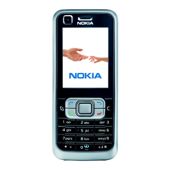
RM-243 also supports MIDP Java 2.0, providing a good platform for compelling 3rd party applications. Figure 1 View of RM-243 Product features and sales package Bearers and transport • WCDMA DL 384kbit/s, UL 384 kbit/s Issue 1 COMPANY CONFIDENTIAL Page 1 –5 Copyright © 2007 Nokia. All rights reserved. - Page 16 • OMA client provisioning • PIM (Calendar + Contacts) • OTA provisioning & over the air SW update (FOTA) • Nokia PC Suite connectivity with USB, Bluetooth • Active Standby • Local/remote SyncML data sync • Web Browser (OSS), Java ™ MIDP 2.0, XHTML browsing over TCP/IP Messaging •...
-
Page 17: Product And Module List
RM-243 General Information Add-on software framework • Symbian 9.x OS • Nokia Series 60, 3rd edition, feature pack 3.1 • Java: MIDP2.0 Additional technical specifications • Vibrating alert • 3GPP Rel 4compliant • Speech codecs supported in WCDMA: AMR • Speech codecs supported in GSM: AMR, EFR, FR, HR •... -
Page 18: Table 2 Car
Table 4 Data & positioning Enhancement Type MicroSD card, 128MB MU-26 MicroSD card, 256MB MU-27 MicroSD card, 512MB MU-28 MicroSD card, 1GB MU-22 MicroSD card, 2GB MU-37 Page 1 –8 COMPANY CONFIDENTIAL Issue 1 Copyright © 2007 Nokia. All rights reserved. -
Page 19: Technical Specifications
Main RF characteristics for GSM850/900/1800/1900 and WCDMA V (850) and WCDMA I (2100) phones Parameter Unit Cellular system GSM850, EGSM900, GSM1800/1900, WCDMA V (850) and WCDMA I (2100) Issue 1 COMPANY CONFIDENTIAL Page 1 –9 Copyright © 2007 Nokia. All rights reserved. - Page 20 WCDMA I (2100): 277 Channel spacing 200 kHz Number of Tx power levels GSM850: 15 GSM900: 15 GSM1800: 16 GSM1900: 16 WCDMA V (850): 75 WCDMA I (2100): 75 Page 1 –10 COMPANY CONFIDENTIAL Issue 1 Copyright © 2007 Nokia. All rights reserved.
-
Page 21: Battery Endurance
BL-5B up to 190 min (GSM) up to 9 days (GSM) up to 150 min (WCDMA) up to 9 days (WCDMA) Charging times AC-4 80 min Issue 1 COMPANY CONFIDENTIAL Page 1 –11 Copyright © 2007 Nokia. All rights reserved. - Page 22 RM-243 General Information (This page left intentionally blank.) Page 1 –12 COMPANY CONFIDENTIAL Issue 1 Copyright © 2007 Nokia. All rights reserved.
- Page 23 Nokia Customer Care 2 — Service Tools and Service Concepts Issue 1 COMPANY CONFIDENTIAL Page 2 –1 Copyright © 2007 Nokia. All rights reserved.
- Page 24 RM-243 Service Tools and Service Concepts (This page left intentionally blank.) Page 2 –2 COMPANY CONFIDENTIAL Issue 1 Copyright © 2007 Nokia. All rights reserved.
-
Page 25: Table Of Contents
Module jig service concept ..........................2–18 RF testing concept with RF coupler ......................2–19 Service concept for RF testing and RF/BB tuning ..................2–20 List of Tables Issue 1 COMPANY CONFIDENTIAL Page 2 –3 Copyright © 2007 Nokia. All rights reserved. - Page 26 Figure 5 Module jig service concept ........................2–18 Figure 6 RF testing concept with RF coupler ....................2–19 Figure 7 Service concept for RF testing and RF/BB tuning ................2–20 Page 2 –4 COMPANY CONFIDENTIAL Issue 1 Copyright © 2007 Nokia. All rights reserved.
-
Page 27: Service Tools
The jig includes an RF interface for GSM, WCDMA and Bluetooth. RJ-176 Soldering jig RJ-176 is a soldering jig used for soldering and as a rework jig for the engine module. Issue 1 COMPANY CONFIDENTIAL Page 2 –5 Copyright © 2007 Nokia. All rights reserved. -
Page 28: General Tools
The table below gives a short overview of service tools that can be used for testing, error analysis and repair of product RM-243, refer to various concepts. Page 2 –6 COMPANY CONFIDENTIAL Issue 1 Copyright © 2007 Nokia. All rights reserved. - Page 29 4 Connect an FBUS cable (if necessary). 5 Start Phoenix service software. Note: Phoenix enables CU-4 regulators via USB when it is started. Reconnecting the power supply requires a Phoenix restart. Issue 1 COMPANY CONFIDENTIAL Page 2 –7 Copyright © 2007 Nokia. All rights reserved.
- Page 30 WCDMA network, a shield box is needed in all testing, tuning and fault finding which requires WCDMA RF signal. The shield box is not an active device, it contains only passive filtering components for RF attenuation. Page 2 –8 COMPANY CONFIDENTIAL Issue 1 Copyright © 2007 Nokia. All rights reserved.
- Page 31 ST-55 stencil. RJ-160 Rework jig RJ-160 is a rework jig used when servicing the WCDMA duplexer (Z7541). It is used together with the ST-55 stencil. Issue 1 COMPANY CONFIDENTIAL Page 2 –9 Copyright © 2007 Nokia. All rights reserved.
- Page 32 AXS-4 cable in case of cordless interface usage testing . Sales package includes: • SB-6 test box • Installation and warranty information SPS-1 Soldering Paste Spreader Page 2 –10 COMPANY CONFIDENTIAL Issue 1 Copyright © 2007 Nokia. All rights reserved.
- Page 33 • provides standardised interface towards Control Unit • provides RF connection using galvanic connector or coupler • multiplexing between USB and FBUS media, controlled by VUSB Issue 1 COMPANY CONFIDENTIAL Page 2 –11 Copyright © 2007 Nokia. All rights reserved.
- Page 34 SX-4 is a BB5 security device used to protect critical features in tuning and testing. SX-4 is also needed together with FPS-10 when DCT-4 phones are flashed. Page 2 –12 COMPANY CONFIDENTIAL Issue 1 Copyright © 2007 Nokia. All rights reserved.
-
Page 35: Cables
Product-specific adapter cable for RF tuning. Table 8 Attenuation values • Band Attenuation Rx/Tx GSM850/900 0.2...0.3 dB GSM1800/1900 0.3...0.4 dB WCDMA850 0.2...0.3 dB WCDMA2100 0.4...0.6 dB Issue 1 COMPANY CONFIDENTIAL Page 2 –13 Copyright © 2007 Nokia. All rights reserved. -
Page 36: Dau-9S
XCS-4 Modular cable XCS-4 is a shielded (one specially shielded conductor) modular cable for flashing and service purposes. Page 2 –14 COMPANY CONFIDENTIAL Issue 1 Copyright © 2007 Nokia. All rights reserved. -
Page 37: Service Concepts
POS (Point of Sale) flash concept Figure 2 POS flash concept Type Description Product specific tools BL-5B Battery Other tools FLS-5 POS flash dongle PC with Phoenix service software Cables Issue 1 COMPANY CONFIDENTIAL Page 2 –15 Copyright © 2007 Nokia. All rights reserved. -
Page 38: Flash Concept With Fps-10
Other devices FPS-10 Flash prommer box PKD-1/PK-1 SW security device SS-46 Interface adapter PC with Phoenix service software Cables XCS-4 Modular cable CA-35S Power cable USB cable Page 2 –16 COMPANY CONFIDENTIAL Issue 1 Copyright © 2007 Nokia. All rights reserved. -
Page 39: Flash Concept With Fps-10
SW security device SS-62 Flash adapter base SX-4 Smart card PC with Phoenix service software Cables PCS-1 Power cable XCS-4 Modular cable Standard USB cable USB cable Issue 1 COMPANY CONFIDENTIAL Page 2 –17 Copyright © 2007 Nokia. All rights reserved. -
Page 40: Module Jig Service Concept
PC with Phoenix service software Measurement equipment Cables CA-58RS RF service cable (product-specific adapter cable) PCS-1 DC power cable XCS-4 Modular cable XRS-6 RF cable USB cable GPIB control cable Page 2 –18 COMPANY CONFIDENTIAL Issue 1 Copyright © 2007 Nokia. All rights reserved. -
Page 41: Rf Testing Concept With Rf Coupler
Flash prommer box PKD-1/PK-1 SW security device SS-62 Flash adapter base Measurement equipment PC with Phoenix service software Cables PCS-1 Power cable XCS-4 Modular cable XRS-6 RF cable Issue 1 COMPANY CONFIDENTIAL Page 2 –19 Copyright © 2007 Nokia. All rights reserved. -
Page 42: Service Concept For Rf Testing And Rf/Bb Tuning
Other devices CU-4 Control unit PKD-1/PK-1 SW security device SX-4 Smart card Measurement equipment Smart card reader PC with Phoenix service software Cables DAU-9s MBUS cable Page 2 –20 COMPANY CONFIDENTIAL Issue 1 Copyright © 2007 Nokia. All rights reserved. - Page 43 RM-243 Service Tools and Service Concepts Type Description PCS-1 DC power cable XRS-6 RF cable GPIB control cable USB cable Issue 1 COMPANY CONFIDENTIAL Page 2 –21 Copyright © 2007 Nokia. All rights reserved.
- Page 44 RM-243 Service Tools and Service Concepts (This page left intentionally blank.) Page 2 –22 COMPANY CONFIDENTIAL Issue 1 Copyright © 2007 Nokia. All rights reserved.
- Page 45 Nokia Customer Care 3 — BB Troubleshooting and Manual Tuning Guide Issue 1 COMPANY CONFIDENTIAL Page 3 –1 Copyright © 2007 Nokia. All rights reserved.
- Page 46 RM-243 BB Troubleshooting and Manual Tuning Guide (This page left intentionally blank.) Page 3 –2 COMPANY CONFIDENTIAL Issue 1 Copyright © 2007 Nokia. All rights reserved.
-
Page 47: Table 7 Power
............................3–22 Table 11 Calibration value limits ........................3–46 List of Figures Figure 8 Charging backup battery ........................3–10 Figure 9 Discharging backup battery ........................ 3–10 Issue 1 COMPANY CONFIDENTIAL Page 3 –3 Copyright © 2007 Nokia. All rights reserved. - Page 48 (measured at speaker pads). No filter is used..............3–35 Figure 17 Single-ended output waveform of the Ext_in_Ext_out loop............3–35 Figure 18 Single-ended output waveform of the HP_microphone_in_Ext_out loop........3–35 Page 3 –4 COMPANY CONFIDENTIAL Issue 1 Copyright © 2007 Nokia. All rights reserved.
-
Page 49: Troubleshooting Overview
BB Troubleshooting and Manual Tuning Guide Troubleshooting overview For practical reasons, troubleshooting is divided into two sections; • Baseband troubleshooting, including camera, FM radio and Bluetooth. • RF troubleshooting Issue 1 COMPANY CONFIDENTIAL Page 3 –5 Copyright © 2007 Nokia. All rights reserved. -
Page 50: Dead Or Jammed Device Troubleshooting
RM-243 BB Troubleshooting and Manual Tuning Guide Dead or jammed device troubleshooting Troubleshooting flow Page 3 –6 COMPANY CONFIDENTIAL Issue 1 Copyright © 2007 Nokia. All rights reserved. -
Page 51: General Power Checking
VOUT BETTY Audio switch VANA_CAM External Camera VDIG_CAM External Camera SMPS LEDOUT BETTY LED Display driver and key LEDs 2.85 MicroSD levelshifter card VDDI External Display Issue 1 COMPANY CONFIDENTIAL Page 3 –7 Copyright © 2007 Nokia. All rights reserved. -
Page 52: Clocking Troubleshooting
RM-243 BB Troubleshooting and Manual Tuning Guide Clocking troubleshooting Troubleshooting flow Page 3 –8 COMPANY CONFIDENTIAL Issue 1 Copyright © 2007 Nokia. All rights reserved. -
Page 53: Charging Troubleshooting
RM-243 BB Troubleshooting and Manual Tuning Guide Charging troubleshooting Troubleshooting flow Issue 1 COMPANY CONFIDENTIAL Page 3 –9 Copyright © 2007 Nokia. All rights reserved. -
Page 54: Backup Battery Troubleshooting
If the voltage stays ~0V, check resistance VBACK against GND. If there is no short- circuit, AVILMA is faulty. Replace AVILMA. Page 3 –10 COMPANY CONFIDENTIAL Issue 1 Copyright © 2007 Nokia. All rights reserved. -
Page 55: Flash Programming Fault Troubleshooting
RM-243 BB Troubleshooting and Manual Tuning Guide Flash programming fault troubleshooting Part 1 Issue 1 COMPANY CONFIDENTIAL Page 3 –11 Copyright © 2007 Nokia. All rights reserved. - Page 56 RM-243 BB Troubleshooting and Manual Tuning Guide Part 2 Figure 10 Take single trig measurement for the rise of the BSI signal. Page 3 –12 COMPANY CONFIDENTIAL Issue 1 Copyright © 2007 Nokia. All rights reserved.
-
Page 57: Combo Memory Troubleshooting
RM-243 BB Troubleshooting and Manual Tuning Guide Combo memory troubleshooting Troubleshooting flow Issue 1 COMPANY CONFIDENTIAL Page 3 –13 Copyright © 2007 Nokia. All rights reserved. -
Page 58: Microsd Card Troubleshooting
RM-243 BB Troubleshooting and Manual Tuning Guide MicroSD card troubleshooting Troubleshooting flow Page 3 –14 COMPANY CONFIDENTIAL Issue 1 Copyright © 2007 Nokia. All rights reserved. - Page 59 RM-243 BB Troubleshooting and Manual Tuning Guide Issue 1 COMPANY CONFIDENTIAL Page 3 –15 Copyright © 2007 Nokia. All rights reserved.
-
Page 60: Usb Interface Troubleshooting
RM-243 BB Troubleshooting and Manual Tuning Guide USB interface troubleshooting Troubleshooting flow Page 3 –16 COMPANY CONFIDENTIAL Issue 1 Copyright © 2007 Nokia. All rights reserved. -
Page 61: Sim Card Troubleshooting
RM-243 BB Troubleshooting and Manual Tuning Guide SIM card troubleshooting Troubleshooting flow Issue 1 COMPANY CONFIDENTIAL Page 3 –17 Copyright © 2007 Nokia. All rights reserved. - Page 62 RM-243 BB Troubleshooting and Manual Tuning Guide Page 3 –18 COMPANY CONFIDENTIAL Issue 1 Copyright © 2007 Nokia. All rights reserved.
-
Page 63: Keyboard Troubleshooting
(shortcut or open connection). For a more detailed description of the keyboard and keymatrix, see section Keyboard. If the failure mode is not clear, start with the Keyboard Test in Phoenix. Troubleshooting flow Issue 1 COMPANY CONFIDENTIAL Page 3 –19 Copyright © 2007 Nokia. All rights reserved. -
Page 64: Power Key Troubleshooting
RM-243 BB Troubleshooting and Manual Tuning Guide Power key troubleshooting Troubleshooting flow Page 3 –20 COMPANY CONFIDENTIAL Issue 1 Copyright © 2007 Nokia. All rights reserved. -
Page 65: Vibra Troubleshooting
• The display is in a normal mode when the phone is in active use. • Display is in a partial idle mode when the phone is in the screen saver mode. Issue 1 COMPANY CONFIDENTIAL Page 3 –21 Copyright © 2007 Nokia. All rights reserved. - Page 66 Start iii Read the phone information to check that also the application engine is functioning normally (you should be able to read the APE ID). Page 3 –22 COMPANY CONFIDENTIAL Issue 1 Copyright © 2007 Nokia. All rights reserved.
- Page 67 BB Troubleshooting and Manual Tuning Guide 3. Proceed to the display troubleshooting flowcharts. Phoenix to find the detailed fault mode. Use the Display Test tool in Issue 1 COMPANY CONFIDENTIAL Page 3 –23 Copyright © 2007 Nokia. All rights reserved.
-
Page 68: Display Troubleshooting
RM-243 BB Troubleshooting and Manual Tuning Guide Display troubleshooting Troubleshooting flow Page 3 –24 COMPANY CONFIDENTIAL Issue 1 Copyright © 2007 Nokia. All rights reserved. -
Page 69: Backlights And Led Driver Troubleshooting
Keyboard backlights can be turned ON/ OFF separately but not without switching on the display lights. Issue 1 COMPANY CONFIDENTIAL Page 3 –25 Copyright © 2007 Nokia. All rights reserved. -
Page 70: Bluetooth And Fm Radio
BB Troubleshooting and Manual Tuning Guide Troubleshooting flow Bluetooth and FM radio Introduction to Bluetooth/FM Radio troubleshooting There are two main Bluetooth problems that can occur: Page 3 –26 COMPANY CONFIDENTIAL Issue 1 Copyright © 2007 Nokia. All rights reserved. - Page 71 The main issue is to find out if the problem is related to the BT antenna or related to the BT system or the phone’s BB and then replace/fix the faulty component. Bluetooth antenna Figure 11 RM-243 Bluetooth antenna Issue 1 COMPANY CONFIDENTIAL Page 3 –27 Copyright © 2007 Nokia. All rights reserved.
-
Page 72: Bluetooth Settings For Phoenix
7. Place the SB-6 box near (within 10 cm) the BT antenna and click Run BER Test. Results Bit Error Rate (BER) Tests pane in the Bluetooth LOCALS window. Bit Error Rate test result is displayed in the Page 3 –28 COMPANY CONFIDENTIAL Issue 1 Copyright © 2007 Nokia. All rights reserved. -
Page 73: Bluetooth Self Tests In Phoenix
4. From the Mode drop-down menu, set mode to Local. 5. Choose Testing→Self Tests. Self Tests window check the following Bluetooth related tests: 6. In the • ST_LPRF_IF_TEST • ST_LPRF_AUDIO_LINES_TEST • ST_BT_WAKEUP_TEST Issue 1 COMPANY CONFIDENTIAL Page 3 –29 Copyright © 2007 Nokia. All rights reserved. - Page 74 RM-243 BB Troubleshooting and Manual Tuning Guide 7. To run the tests, click Start. Figure 14 Bluetooth self tests in Phoenix Page 3 –30 COMPANY CONFIDENTIAL Issue 1 Copyright © 2007 Nokia. All rights reserved.
-
Page 75: Bluetooth Troubleshooting
RM-243 BB Troubleshooting and Manual Tuning Guide Bluetooth troubleshooting Troubleshooting flow Issue 1 COMPANY CONFIDENTIAL Page 3 –31 Copyright © 2007 Nokia. All rights reserved. -
Page 76: Fm Radio Troubleshooting
RM-243 BB Troubleshooting and Manual Tuning Guide FM radio troubleshooting Troubleshooting flow Page 3 –32 COMPANY CONFIDENTIAL Issue 1 Copyright © 2007 Nokia. All rights reserved. -
Page 77: Audio Troubleshooting
Earpiece, internal microphone and speaker are in place during measurement. Applying a headset accessory during measurement causes a significant drop in measured quantities. The gain values presented in the table apply for a differential output vs. single-ended/differential input. Issue 1 COMPANY CONFIDENTIAL Page 3 –33 Copyright © 2007 Nokia. All rights reserved. - Page 78 1kHz Earpiece sine wave HS_EAR_R & Measurement data Earpiece signal Figure 15 Single-ended output waveform of the Ext_in_HP_out measurement when earpiece is connected. Integrated handsfree signal Page 3 –34 COMPANY CONFIDENTIAL Issue 1 Copyright © 2007 Nokia. All rights reserved.
- Page 79 External output from AV Figure 17 Single-ended output waveform of the Ext_in_Ext_out loop. External output from AV (acoustic input) Figure 18 Single-ended output waveform of the HP_microphone_in_Ext_out loop. Issue 1 COMPANY CONFIDENTIAL Page 3 –35 Copyright © 2007 Nokia. All rights reserved.
-
Page 80: Internal Earpiece Troubleshooting
RM-243 BB Troubleshooting and Manual Tuning Guide Internal earpiece troubleshooting Troubleshooting flow Page 3 –36 COMPANY CONFIDENTIAL Issue 1 Copyright © 2007 Nokia. All rights reserved. -
Page 81: Internal Microphone Troubleshooting
RM-243 BB Troubleshooting and Manual Tuning Guide Internal microphone troubleshooting Troubleshooting flow Issue 1 COMPANY CONFIDENTIAL Page 3 –37 Copyright © 2007 Nokia. All rights reserved. -
Page 82: Ihf Speakers Troubleshooting
RM-243 BB Troubleshooting and Manual Tuning Guide IHF speakers troubleshooting Troubleshooting flow Page 3 –38 COMPANY CONFIDENTIAL Issue 1 Copyright © 2007 Nokia. All rights reserved. -
Page 83: External Headset Microphone Troubleshooting
RM-243 BB Troubleshooting and Manual Tuning Guide External headset microphone troubleshooting Troubleshooting flow Issue 1 COMPANY CONFIDENTIAL Page 3 –39 Copyright © 2007 Nokia. All rights reserved. -
Page 84: External Headset Earpiece Troubleshooting
RM-243 BB Troubleshooting and Manual Tuning Guide External headset earpiece troubleshooting Troubleshooting flow Page 3 –40 COMPANY CONFIDENTIAL Issue 1 Copyright © 2007 Nokia. All rights reserved. -
Page 85: Acoustics Troubleshooting
The phone should be dry and clean, and no objects must be located in such a way that they close any of the holes. Issue 1 COMPANY CONFIDENTIAL Page 3 –41 Copyright © 2007 Nokia. All rights reserved. -
Page 86: Earpiece Troubleshooting
RM-243 BB Troubleshooting and Manual Tuning Guide Earpiece troubleshooting Troubleshooting flow Page 3 –42 COMPANY CONFIDENTIAL Issue 1 Copyright © 2007 Nokia. All rights reserved. -
Page 87: Ihf Troubleshooting
RM-243 BB Troubleshooting and Manual Tuning Guide IHF troubleshooting Troubleshooting flow Issue 1 COMPANY CONFIDENTIAL Page 3 –43 Copyright © 2007 Nokia. All rights reserved. -
Page 88: Microphone Troubleshooting
RM-243 BB Troubleshooting and Manual Tuning Guide Microphone troubleshooting Troubleshooting flow Page 3 –44 COMPANY CONFIDENTIAL Issue 1 Copyright © 2007 Nokia. All rights reserved. -
Page 89: Baseband Manual Tuning Guide
2. Execute the certificate restore process in Phoenix. Next actions Phoenix tuning functions. After a successful rewrite, you must retune the phone completely by using Important: Perform all tunings: RF, BB, and UI. Issue 1 COMPANY CONFIDENTIAL Page 3 –45 Copyright © 2007 Nokia. All rights reserved. -
Page 90: Energy Management Calibration
Write and/or repeat the procedure again. Energy Management Calibration window. 10. To end the procedure, close the Page 3 –46 COMPANY CONFIDENTIAL Issue 1 Copyright © 2007 Nokia. All rights reserved. - Page 91 Nokia Customer Care 4 — RF troubleshooting Issue 1 COMPANY CONFIDENTIAL Page 4 –1 Copyright © 2007 Nokia. All rights reserved.
- Page 92 RM-243 RF troubleshooting (This page left intentionally blank.) Page 4 –2 COMPANY CONFIDENTIAL Issue 1 Copyright © 2007 Nokia. All rights reserved.
- Page 93 Tx LO leakage (WCDMA) ..........................4–53 List of Tables Table 12 Rf channel filter calibration tuning limits ..................4–31 Table 13 RF tuning limits in Rx calibration....................... 4–34 Issue 1 COMPANY CONFIDENTIAL Page 4 –3 Copyright © 2007 Nokia. All rights reserved.
- Page 94 Figure 31 Pop-up window for WCDMA2100...................... 4–43 Figure 32 Pop-up window for WCDMA2100...................... 4–45 Figure 33 WCDMA power level tuning steps ..................... 4–47 Figure 34 High burst measurement ........................4–49 Page 4 –4 COMPANY CONFIDENTIAL Issue 1 Copyright © 2007 Nokia. All rights reserved.
-
Page 95: General Rf Troubleshooting
The scope of this guideline is to enable repairs at key-component level. Some key-components are not accessible without replacing the whole shield frame (i.e. not replaceable). Please refer to the list of Non- replaceable RF components (page 4–7). Issue 1 COMPANY CONFIDENTIAL Page 4 –5 Copyright © 2007 Nokia. All rights reserved. -
Page 96: Rf Key Components
RM-243 RF troubleshooting RF key components Figure 19 RF key components - bottom Page 4 –6 COMPANY CONFIDENTIAL Issue 1 Copyright © 2007 Nokia. All rights reserved. -
Page 97: Non-Replaceable Rf Components
RM-243 RF troubleshooting Non-replaceable RF components Because of their location on the PWB, the following RF components cannot be replaced without replacing the whole shield frame: Issue 1 COMPANY CONFIDENTIAL Page 4 –7 Copyright © 2007 Nokia. All rights reserved. -
Page 98: General Voltage Checking
Vbat at WCDMA PA C7547 3.9 V Supply input to DC/DC conv L7592 3.9 V * With these settings, the result should be 1.3 V. Page 4 –8 COMPANY CONFIDENTIAL Issue 1 Copyright © 2007 Nokia. All rights reserved. -
Page 99: Phoenix Self Tests
Figure 20 General voltage checking test points Phoenix self tests Context Always start the troubleshooting procedure by running the Phoenix self tests. If a test fails, please follow the diagram below. Issue 1 COMPANY CONFIDENTIAL Page 4 –9 Copyright © 2007 Nokia. All rights reserved. - Page 100 Dead or jammed device troubleshooting. If the phone is dead and you cannot perform the self tests, go to in the baseband troubleshooting section. Troubleshooting flow Page 4 –10 COMPANY CONFIDENTIAL Issue 1 Copyright © 2007 Nokia. All rights reserved.
-
Page 101: Vctcxo Troubleshooting
RM-243 RF troubleshooting VCTCXO troubleshooting Troubleshooting flow Issue 1 COMPANY CONFIDENTIAL Page 4 –11 Copyright © 2007 Nokia. All rights reserved. -
Page 102: Receiver Troubleshooting
GSM RX chain activation for manual measurements / GSM RSSI measurement (page 4–17). For a similar test in WCDMA mode, see WCDMA RSSI measurement (page 4–20). Page 4 –12 COMPANY CONFIDENTIAL Issue 1 Copyright © 2007 Nokia. All rights reserved. -
Page 103: Rx Gsm850 Troubleshooting
RM-243 RF troubleshooting RX GSM850 troubleshooting Troubleshooting flow Issue 1 COMPANY CONFIDENTIAL Page 4 –13 Copyright © 2007 Nokia. All rights reserved. -
Page 104: Rx Gsm900 Troubleshooting
RM-243 RF troubleshooting RX GSM900 troubleshooting Troubleshooting flow Page 4 –14 COMPANY CONFIDENTIAL Issue 1 Copyright © 2007 Nokia. All rights reserved. -
Page 105: Rx Gsm1800 Troubleshooting
RM-243 RF troubleshooting RX GSM1800 troubleshooting Troubleshooting flow Issue 1 COMPANY CONFIDENTIAL Page 4 –15 Copyright © 2007 Nokia. All rights reserved. -
Page 106: Rx Gsm1900 Troubleshooting
RM-243 RF troubleshooting RX GSM1900 troubleshooting Troubleshooting flow Page 4 –16 COMPANY CONFIDENTIAL Issue 1 Copyright © 2007 Nokia. All rights reserved. -
Page 107: Gsm Rx Chain Activation For Manual Measurements/Gsm Rssi Measurement
The reading should reflect the level of the signal generator (-losses) +/- 5 dB. When varying the level in the range -30 to -102 dBm the reading should then follow within +/-5 dB. Issue 1 COMPANY CONFIDENTIAL Page 4 –17 Copyright © 2007 Nokia. All rights reserved. -
Page 108: Wcdma Receiver Troubleshooting
RM-243 RF troubleshooting WCDMA receiver troubleshooting Troubleshooting flow Page 4 –18 COMPANY CONFIDENTIAL Issue 1 Copyright © 2007 Nokia. All rights reserved. -
Page 109: Wcdma Rx Chain Activation For Manual Measurement
If the settings are changed later on (for example, change of channel) you have to click Stop and Start again. Note: Clicking Stop also disables TX control if it was active. 4. Set the following RF generator settings: Issue 1 COMPANY CONFIDENTIAL Page 4 –19 Copyright © 2007 Nokia. All rights reserved. -
Page 110: Wcdma Rssi Measurement
• The most useful Phoenix tool for GSM transmitter testing is “RF Controls”; in WCDMA transmitter testing the best tool is “TX Control”. • Remember that re-tuning is not a fix! Phones are tuned correctly in production Page 4 –20 COMPANY CONFIDENTIAL Issue 1 Copyright © 2007 Nokia. All rights reserved. -
Page 111: Gsm Transmitter Troubleshooting
2. Activate RF controls in Phoenix (Testing→GSM→Rf Controls ). Use the following settings: 3. Check the basic TX parameters (i.e. power, phase error, modulation and switching spectrum), using a communication analyser (for example CMU200). Issue 1 COMPANY CONFIDENTIAL Page 4 –21 Copyright © 2007 Nokia. All rights reserved. - Page 112 You can troubleshoot the GSM transmitter for each GSM band separately, one band at a time. If you want to troubleshoot GSM850, GSM1800 or GSM1900, change the band with the RF controls and set the communication analyser accordingly. Page 4 –22 COMPANY CONFIDENTIAL Issue 1 Copyright © 2007 Nokia. All rights reserved.
-
Page 113: Tx 850/900 Troubleshooting
RM-243 RF troubleshooting TX 850/900 troubleshooting Troubleshooting flow Issue 1 COMPANY CONFIDENTIAL Page 4 –23 Copyright © 2007 Nokia. All rights reserved. -
Page 114: Tx 1800/1900 Troubleshooting
RM-243 RF troubleshooting TX 1800/1900 troubleshooting Troubleshooting flow Page 4 –24 COMPANY CONFIDENTIAL Issue 1 Copyright © 2007 Nokia. All rights reserved. -
Page 115: Checking Antenna Functionality
PWB's C-clips, and the antenna foil is visually intact in the antenna frame. The main antenna functionality must also be checked by measuring the transmitted power with RF coupler at GSM900 channel 124. Figure 23 Main antenna components Issue 1 COMPANY CONFIDENTIAL Page 4 –25 Copyright © 2007 Nokia. All rights reserved. - Page 116 The BT antenna is functioning normally when the BT antenna contacts take proper contact to the PWB's C- clips, and the BT antenna assembly is visually intact in the C-cover. Figure 25 BT antenna location Page 4 –26 COMPANY CONFIDENTIAL Issue 1 Copyright © 2007 Nokia. All rights reserved.
-
Page 117: Wcdma Transmitter Troubleshooting
WCDMA transmitter troubleshooting Steps 1. Set the phone to local mode. 2. In Phoenix, select Testing→WCDMA→TX control . 3. Use the following settings in the TX control window: Issue 1 COMPANY CONFIDENTIAL Page 4 –27 Copyright © 2007 Nokia. All rights reserved. - Page 118 If settings are changed (eg. new channel), you have to click RF Stop and Send again. 5. Use the CMU200 to check the WCDMA power. Figure 28 WCDMA power window Page 4 –28 COMPANY CONFIDENTIAL Issue 1 Copyright © 2007 Nokia. All rights reserved.
-
Page 119: Wcdma Transmitter Troubleshooting Flowchart
RM-243 RF troubleshooting WCDMA transmitter troubleshooting flowchart Troubleshooting flow RF tunings Introduction to RF tunings Important: Only perform RF tunings if: Issue 1 COMPANY CONFIDENTIAL Page 4 –29 Copyright © 2007 Nokia. All rights reserved. -
Page 120: Autotuning For Bb5
• Signal analyser (TX), signal generator (RX) and RF-splitter Figure 29 Auto tuning concept with CMU200 Phoenix preparations Install the phone-specific data package. This defines the phone-specific settings. Page 4 –30 COMPANY CONFIDENTIAL Issue 1 Copyright © 2007 Nokia. All rights reserved. -
Page 121: System Mode Independent Manual Tunings
Figure 30 Rf channel filter calibration typical values PA (power amplifier) detection Context The PA detection procedure detects which PA manufacturer is used for phone PAs. Issue 1 COMPANY CONFIDENTIAL Page 4 –31 Copyright © 2007 Nokia. All rights reserved. -
Page 122: Gsm Receiver Tunings
1. Connect the GSM connector of the module jig to a signal generator. Phoenix service software. 2. Start 3. From the Operating mode drop-down menu, set mode to Local. 4. Choose Tuning→GSM→Rx Calibration . Page 4 –32 COMPANY CONFIDENTIAL Issue 1 Copyright © 2007 Nokia. All rights reserved. - Page 123 Rx Calibration with band EGSM900 (step 1-3) pop-up window. Important: The calibration uses a non-modulated CW signal. Increase the signal generator level by cable attenuation and module jig probe attenuation. Issue 1 COMPANY CONFIDENTIAL Page 4 –33 Copyright © 2007 Nokia. All rights reserved.
- Page 124 -80..40 AFC slope 108..121 RSSI (AGC-0) 107..110 GSM900 AFC Value (init) -200 -105..62 AFC slope RSSI (AGC-0) 107...110 GSM1800 RSSI (AGC-0) 105...109 GSM1900 RSSI (AGC-0) 105...109 Page 4 –34 COMPANY CONFIDENTIAL Issue 1 Copyright © 2007 Nokia. All rights reserved.
-
Page 125: Rx Band Filter Response Compensation (Gsm)
Connect the GSM connector of the module jig to a signal generator. Phoenix service software. Start From the Operating mode drop-down menu, set mode to Local. Issue 1 COMPANY CONFIDENTIAL Page 4 –35 Copyright © 2007 Nokia. All rights reserved. - Page 126 Rx Band Connect the signal generator to the phone, and set frequency and amplitude as instructed in the Filter Response Compensation for EGSM900 pop-up window, step 1-3. Page 4 –36 COMPANY CONFIDENTIAL Issue 1 Copyright © 2007 Nokia. All rights reserved.
- Page 127 Ch. 251/893.86771 MHz Ch. 261/895.86771 MHz GSM900 Ch. 965 / 923.26771 MHz Ch. 975 / 925.26771 MHz Ch. 987 / 927.66771 MHz Ch. 1009 / 932.06771 MHz Issue 1 COMPANY CONFIDENTIAL Page 4 –37 Copyright © 2007 Nokia. All rights reserved.
-
Page 128: Gsm Transmitter Tunings
The Tx path branches to I and Q signals at RF I/Q modulator. Modulator and analog hardware located after it cause unequal amplitude and phase disturbance to I and Q signal paths. Tx IQ tuning balances the I and Q branches. Page 4 –38 COMPANY CONFIDENTIAL Issue 1 Copyright © 2007 Nokia. All rights reserved. - Page 129 If they are not within the limits, check Tx IQ quality manually. Unit GSM850 I DC offset / Q DC offset Ampl Phase ° GSM900 Issue 1 COMPANY CONFIDENTIAL Page 4 –39 Copyright © 2007 Nokia. All rights reserved.
-
Page 130: Tx Power Level Tuning (Gsm)
Connect the phone to a spectrum analyzer. Phoenix service software. Start From the Operating mode drop-down menu, set mode to Local. Choose Tuning→GSM→Tx Power Level Tuning . Page 4 –40 COMPANY CONFIDENTIAL Issue 1 Copyright © 2007 Nokia. All rights reserved. - Page 131 Reference level 33dBm A power meter with a peak power detector can be also used. Remember to take the attenuations into account. Issue 1 COMPANY CONFIDENTIAL Page 4 –41 Copyright © 2007 Nokia. All rights reserved.
- Page 132 10. Adjust power for all bold power levels to correspond the Target dBm column by pressing + or – keys. Next actions Continue tuning the bold power levels of the GSM900, GSM1800 and GSM1900 bands. You will see this message, if finished successfully: Page 4 –42 COMPANY CONFIDENTIAL Issue 1 Copyright © 2007 Nokia. All rights reserved.
-
Page 133: Wcdma Receiver Tunings
5. Click Tune. Rx Calibration pop-up window and click 6. Setup the signal generator to correspond with the values on the, Figure 31 Pop-up window for WCDMA2100 Issue 1 COMPANY CONFIDENTIAL Page 4 –43 Copyright © 2007 Nokia. All rights reserved. - Page 134 • In the Tuning menu, choose WCDMA→ Rx Calibration . • Click Start. • Select Band, "WCDMA2100 or WCDMA850". • Check the Sweep Mode box. • Click Tune. Page 4 –44 COMPANY CONFIDENTIAL Issue 1 Copyright © 2007 Nokia. All rights reserved.
-
Page 135: Wcdma Transmitter Tunings
From the Operating mode drop-down menu, set mode to Local. Choose Tuning→WCDMA→Tx AGC & Power Detector. Click Start. Wide Range pane, click Tune (the leftmost Tune button). In the Issue 1 COMPANY CONFIDENTIAL Page 4 –45 Copyright © 2007 Nokia. All rights reserved. - Page 136 It must be possible to measure power levels down to –68 dBm. The measured power levels must be monotonously decreasing. Make sure that the marker is not measuring the level of noise spikes on lower levels. Page 4 –46 COMPANY CONFIDENTIAL Issue 1 Copyright © 2007 Nokia. All rights reserved.
- Page 137 RM-243 RF troubleshooting Figure 33 WCDMA power level tuning steps Issue 1 COMPANY CONFIDENTIAL Page 4 –47 Copyright © 2007 Nokia. All rights reserved.
- Page 138 Fill in the power level values (in dBm) to the Wide Range pane, click Calculate. In the High Burst pane, click Tune. 10. In the 11. Adjust the spectrum analyzer according to the following settings: Page 4 –48 COMPANY CONFIDENTIAL Issue 1 Copyright © 2007 Nokia. All rights reserved.
- Page 139 14. Check that the calculated values are within the limits specified in the following table: C0-high -0.5 C1-high C2-high C0-mid -0.7 C1-mid C2-mid C0-low C1-low -400 C2-low -10000 15000 Issue 1 COMPANY CONFIDENTIAL Page 4 –49 Copyright © 2007 Nokia. All rights reserved.
- Page 140 24 dBm or -20 dBm depending on the level measured Input attenuation: Automatic Resolution bandwidth: 5 MHz Video bandwidth: 5 MHz Sweep time: 20 ms Detector: RMS detector Page 4 –50 COMPANY CONFIDENTIAL Issue 1 Copyright © 2007 Nokia. All rights reserved.
-
Page 141: Tx Band Response Calibration (Wcdma)
• The Read button reads the tuned values in the PM of the terminal, and displays them in the Values pane in in the Current column. Steps Phoenix service software. Start Choose File→Scan Product . Issue 1 COMPANY CONFIDENTIAL Page 4 –51 Copyright © 2007 Nokia. All rights reserved. - Page 142 The tuned values are shown in the 16. Check that the tuned values are within the limits presented in the following table. If they are OK, click Yes. Page 4 –52 COMPANY CONFIDENTIAL Issue 1 Copyright © 2007 Nokia. All rights reserved.
-
Page 143: Tx Lo Leakage (Wcdma)
1. From the Operating mode drop-down menu, set mode to Local. 2. Choose Tuning→WCDMA→ Tx LO Leakage . 3. Click Tune. 4. To end the tuning, click Close. Issue 1 COMPANY CONFIDENTIAL Page 4 –53 Copyright © 2007 Nokia. All rights reserved. - Page 144 RM-243 RF troubleshooting (This page left intentionally blank.) Page 4 –54 COMPANY CONFIDENTIAL Issue 1 Copyright © 2007 Nokia. All rights reserved.
- Page 145 Nokia Customer Care 5 — Camera Module Troubleshooting Issue 1 COMPANY CONFIDENTIAL Page 5 –1 Copyright © 2007 Nokia. All rights reserved.
- Page 146 RM-243 Camera Module Troubleshooting (This page left intentionally blank.) Page 5 –2 COMPANY CONFIDENTIAL Issue 1 Copyright © 2007 Nokia. All rights reserved.
- Page 147 Main (back) camera troubleshooting ........................5–5 Main camera troubleshooting..........................5–5 Camera flash LED troubleshooting ........................5–6 Secondary (front) camera troubleshooting ......................5–7 Secondary camera troubleshooting ........................5–7 Camera hardware failure troubleshooting......................5–8 Issue 1 COMPANY CONFIDENTIAL Page 5 –3 Copyright © 2007 Nokia. All rights reserved.
- Page 148 RM-243 Camera Module Troubleshooting (This page left intentionally blank.) Page 5 –4 COMPANY CONFIDENTIAL Issue 1 Copyright © 2007 Nokia. All rights reserved.
-
Page 149: Main (Back) Camera Troubleshooting
RM-243 Camera Module Troubleshooting Main (back) camera troubleshooting Main camera troubleshooting Troubleshooting flow Issue 1 COMPANY CONFIDENTIAL Page 5 –5 Copyright © 2007 Nokia. All rights reserved. -
Page 150: Camera Flash Led Troubleshooting
RM-243 Camera Module Troubleshooting Camera flash LED troubleshooting Troubleshooting flow Page 5 –6 COMPANY CONFIDENTIAL Issue 1 Copyright © 2007 Nokia. All rights reserved. -
Page 151: Secondary (Front) Camera Troubleshooting
RM-243 Camera Module Troubleshooting Secondary (front) camera troubleshooting Secondary camera troubleshooting Troubleshooting flow Issue 1 COMPANY CONFIDENTIAL Page 5 –7 Copyright © 2007 Nokia. All rights reserved. -
Page 152: Camera Hardware Failure Troubleshooting
RM-243 Camera Module Troubleshooting Camera hardware failure troubleshooting Troubleshooting flow Page 5 –8 COMPANY CONFIDENTIAL Issue 1 Copyright © 2007 Nokia. All rights reserved. - Page 153 Nokia Customer Care 6 — System Module and User Interface Issue 1 COMPANY CONFIDENTIAL Page 6 –1 Copyright © 2007 Nokia. All rights reserved.
- Page 154 RM-243 System Module and User Interface (This page left intentionally blank.) Page 6 –2 COMPANY CONFIDENTIAL Issue 1 Copyright © 2007 Nokia. All rights reserved.
- Page 155 6–23 External interfaces ............................6–23 SIM IF connections............................6–23 Charging interface connections & electrical characteristics ..............6–24 Internal interfaces............................6–24 Back-up battery interface electrical characteristics..................6–24 Issue 1 COMPANY CONFIDENTIAL Page 6 –3 Copyright © 2007 Nokia. All rights reserved.
- Page 156 Figure 49 External earpiece and microphone circuitry (AV connected on the right) ........6–22 Figure 50 Vibra circuitry ............................. 6–22 Figure 51 RF block diagram using RF ASIC N7505 .................... 6–25 Page 6 –4 COMPANY CONFIDENTIAL Issue 1 Copyright © 2007 Nokia. All rights reserved.
-
Page 157: Introduction
D3000 Back-up battery RTC back-up battery 311 G2200 FM radio BTFMRDS2.0D chip N6000 Bluetooth BTFMRDS2.0D chip N6000 Battery BL-5B Battery connector LYNX X2070 RF connector X7501 Issue 1 COMPANY CONFIDENTIAL Page 6 –5 Copyright © 2007 Nokia. All rights reserved. -
Page 158: Energy Management
The phone is powered by a 3-pole BL-5B S-pack 890 mAh battery. The three poles are named VBAT, BSI and GND where the BSI line is used to recognize the battery capacity. This is done by means of an internal battery pull down resistor. Page 6 –6 COMPANY CONFIDENTIAL Issue 1 Copyright © 2007 Nokia. All rights reserved. - Page 159 The BSI line is used to recognize the battery capacity by a battery internal pull down resistor. Figure 36 LYNX battery connector Charging This phone is charged through the smaller Nokia standard interface (2.0 mm plug). The wider standard charger (3.5 mm) can be used together with the CA-44 charger adapter. Issue 1 COMPANY CONFIDENTIAL Page 6 –7...
-
Page 160: Backup Battery
SW Shutdown Voltages Sw shutdown In call Sw shutdown In idle Min Operating Voltage Vcoff+ 2.9 ± 0.1 Off to on Vcoff- 2.6 ± 0.1 On to off Page 6 –8 COMPANY CONFIDENTIAL Issue 1 Copyright © 2007 Nokia. All rights reserved. -
Page 161: Power Key And System Power-Up
SLEEP mode is entered only from PWR_ON mode with the aid of SW when the system’s activity is low. FLASHING FLASHING mode is for SW downloading. Issue 1 COMPANY CONFIDENTIAL Page 6 –9 Copyright © 2007 Nokia. All rights reserved. -
Page 162: Power Distribution
RM-243 System Module and User Interface Power distribution Page 6 –10 COMPANY CONFIDENTIAL Issue 1 Copyright © 2007 Nokia. All rights reserved. -
Page 163: Clocking Scheme
The Bluetooth is physically integrated with the FM radio into a discrete module. From a functional point of view they, however, have nothing in common. Issue 1 COMPANY CONFIDENTIAL Page 6 –11 Copyright © 2007 Nokia. All rights reserved. -
Page 164: Fm Radio
FM radio reception. The radio has an automatic band search function, which can search for a strong station. Page 6 –12 COMPANY CONFIDENTIAL Issue 1 Copyright © 2007 Nokia. All rights reserved. -
Page 165: Usb
The SIM interface consists of an internal interface between RAPIDO and EM ASIC (N2200), and of an external interface between N2200 and SIM contacts. The SIM IF is shown in the following figure: Issue 1 COMPANY CONFIDENTIAL Page 6 –13 Copyright © 2007 Nokia. All rights reserved. -
Page 166: Μsd Card Interface
The µSD card door state is detected by a detect switch. When the door is open, the µSD card is powered off. Hot swap is supported, which means that the card may be plugged in/out at any time, without removing the battery. Page 6 –14 COMPANY CONFIDENTIAL Issue 1 Copyright © 2007 Nokia. All rights reserved. -
Page 167: Camera Concept
The dimensions of the camera flash module are 5.00 ± 0.1 mm x 5.00 ± 0.1 mm x 2.0 ± ? mm (general tolerance ± 0.15 mm). Issue 1 COMPANY CONFIDENTIAL Page 6 –15 Copyright © 2007 Nokia. All rights reserved. -
Page 168: Secondary Camera Characteristics
The display in RM-243 is an active TFT QVGA display that supports up to 16.777.216 colors (320x240 pixels). The interconnection between the LCD module and the engine is implemented with a 24-pin board-to-board connector. Page 6 –16 COMPANY CONFIDENTIAL Issue 1 Copyright © 2007 Nokia. All rights reserved. -
Page 169: Keyboard And Other Keys
The keyboard is placed on the top side of the engine PWB. All keys are connected to same keymatrix made by the RAPIDO genios. Figure 43 Keyboard layout Issue 1 COMPANY CONFIDENTIAL Page 6 –17 Copyright © 2007 Nokia. All rights reserved. -
Page 170: Display And Keypad Backlight
, EMC filter for SIM, microphones etc. Device memories RAP memories NOR flash and SDRAM Modem memory consists of 128 Mbit SDRAM and 128 Mbit NOR flash memories. Page 6 –18 COMPANY CONFIDENTIAL Issue 1 Copyright © 2007 Nokia. All rights reserved. -
Page 171: Combo Memory
A Bluetooth audio and FM radio module, which is connected to the RAPIDO ASIC supports Bluetooth audio and FM radio functionality. Figure 44 Audio block diagram Internal microphone Internal microphone is used for HandPortable (HP) and Internal HandsFree (IHF) call modes. Issue 1 COMPANY CONFIDENTIAL Page 6 –19 Copyright © 2007 Nokia. All rights reserved. -
Page 172: External Microphone
Internal earpiece is used for the HandPortable (HP) call mode. A dynamic 7x11 mm earpiece capsule is connected to Avilma ASIC’s differential output EarP and EarN. Page 6 –20 COMPANY CONFIDENTIAL Issue 1 Copyright © 2007 Nokia. All rights reserved. -
Page 173: Internal Speaker
XearL and XearLC form the left channel audio output, and XearR and XearRC from the right channel audio output. XearLC and XearRC are the ground pins if the output works in a single-ended operation. Issue 1 COMPANY CONFIDENTIAL Page 6 –21 Copyright © 2007 Nokia. All rights reserved. -
Page 174: Vibra Circuitry
HS mic audio 1.3 V Max. negative level - input 0.7 V HSEARL HS EAR L audio SPR requirement output HSEARR HS EAR R audio SPR requirement output Page 6 –22 COMPANY CONFIDENTIAL Issue 1 Copyright © 2007 Nokia. All rights reserved. -
Page 175: Baseband Technical Specifications
EM ASIC N2200 SIM1ClkC Clock signal to SIM card Ground SIMDATA In/Out EM ASIC N2200 SIM1DaC Data input / output SIM_DET EM ASIC N2200 SIMDetX Removal detection Issue 1 COMPANY CONFIDENTIAL Page 6 –23 Copyright © 2007 Nokia. All rights reserved. -
Page 176: Charging Interface Connections & Electrical Characteristics
Back-up battery interface electrical characteristics Table 18 Back-up battery connections Pin name Connection Notes L2207, -> N2200, Back-up battery G2200 is VBack VBack connected to N2200 Page 6 –24 COMPANY CONFIDENTIAL Issue 1 Copyright © 2007 Nokia. All rights reserved. -
Page 177: Rf Description
The receiver functions are implemented in the RF ASIC. Signals with different frequencies take different "ways", being handled by different components. The principle of GSM and WCDMA is the same. Issue 1 COMPANY CONFIDENTIAL Page 6 –25 Copyright © 2007 Nokia. All rights reserved. -
Page 178: Transmitter (Tx)
The transmitter functions are implemented in the RF ASIC. Even though the GSM and WCDMA signals pass different components, the principles of the transmission is the same. Page 6 –26 COMPANY CONFIDENTIAL Issue 1 Copyright © 2007 Nokia. All rights reserved. -
Page 179: Frequency Mappings
RM-243 System Module and User Interface Frequency mappings GSM850 frequencies Issue 1 COMPANY CONFIDENTIAL Page 6 –27 Copyright © 2007 Nokia. All rights reserved. -
Page 180: Egsm900 Frequencies
RM-243 System Module and User Interface EGSM900 frequencies Page 6 –28 COMPANY CONFIDENTIAL Issue 1 Copyright © 2007 Nokia. All rights reserved. -
Page 181: Gsm1800 Frequencies
RM-243 System Module and User Interface GSM1800 frequencies Issue 1 COMPANY CONFIDENTIAL Page 6 –29 Copyright © 2007 Nokia. All rights reserved. -
Page 182: Gsm1900 Frequencies
RM-243 System Module and User Interface GSM1900 frequencies Page 6 –30 COMPANY CONFIDENTIAL Issue 1 Copyright © 2007 Nokia. All rights reserved. -
Page 183: Wcdma V (850) Frequencies
RM-243 System Module and User Interface WCDMA V (850) frequencies Issue 1 COMPANY CONFIDENTIAL Page 6 –31 Copyright © 2007 Nokia. All rights reserved. -
Page 184: Wcdma 2100 Rx Frequencies
RM-243 System Module and User Interface WCDMA 2100 Rx frequencies Page 6 –32 COMPANY CONFIDENTIAL Issue 1 Copyright © 2007 Nokia. All rights reserved. -
Page 185: Wcdma 2100 Tx Frequencies
RM-243 System Module and User Interface WCDMA 2100 Tx frequencies Issue 1 COMPANY CONFIDENTIAL Page 6 –33 Copyright © 2007 Nokia. All rights reserved. - Page 186 RM-243 System Module and User Interface (This page left intentionally blank.) Page 6 –34 COMPANY CONFIDENTIAL Issue 1 Copyright © 2007 Nokia. All rights reserved.
- Page 187 Nokia Customer Care Glossary Issue 1 COMPANY CONFIDENTIAL Page Glossary–1 Copyright © 2007 Nokia. All rights reserved.
- Page 188 RM-243 Glossary (This page left intentionally blank.) Page Glossary–2 COMPANY CONFIDENTIAL Issue 1 Copyright © 2007 Nokia. All rights reserved.
- Page 189 D/A-converter Digital-to-analouge converter Digital-to-analouge converter Digital Battery Interface DBus DSP controlled serial bus connected between UPP_WD2 and Helgo DCT-4 Digital Core Technology Direct memory access Data Package Issue 1 COMPANY CONFIDENTIAL Page Glossary–3 Copyright © 2007 Nokia. All rights reserved.
- Page 190 Integrated hands free IMEI International Mobile Equipment Identity Infrared IrDA Infrared Data Associasion Intelligent software architecture JPEG/JPG Joint Photographic Experts Group Liquid Crystal Display Low Drop Out Page Glossary–4 COMPANY CONFIDENTIAL Issue 1 Copyright © 2007 Nokia. All rights reserved.
- Page 191 Serial control Bus For RF Right Soft Key RS-MMC Reduced size Multi Media Card RSSI Receiving signal strength indicator Reset Switch Real Time Clock (provides date and time) Issue 1 COMPANY CONFIDENTIAL Page Glossary–5 Copyright © 2007 Nokia. All rights reserved.
- Page 192 Peak-to-peak voltage VSIM SIM voltage Wireless application protocol Watchdog XHTML Extensible hypertext markup language Zocus Current sensor, (used to monitor the current flow to and from the battery) Page Glossary–6 COMPANY CONFIDENTIAL Issue 1 Copyright © 2007 Nokia. All rights reserved.