Table of Contents
Advertisement
Quick Links
Advertisement
Table of Contents

Related Manuals for Omron NT612G Series


Summary of Contents for Omron NT612G Series
- Page 1 NT600M Programmable Terminal Operation Manual Revised October 1997...
- Page 3 OMRON. No patent liability is assumed with respect to the use of the information contained herein. Moreover, because OMRON is constantly striving to improve its high-quality products, the information contained in this manual is subject to change without notice.
- Page 5 TABLE OF CONTENTS PRECAUTIONS ....... . . 1 Intended Audience .
- Page 6 TABLE OF CONTENTS SECTION 5 Input Functions ....... . . On-screen Switch Inputs .
- Page 7 Section 7 describes transferring screens online to and from the host computer. Section 8 provides troubleshooting and basic maintenance methods, including battery replacement. Appendices of OMRON products used with PTs, PT specifications, and a memory check table are provided at the back of the manual.
- Page 8 PRECAUTIONS This section provides general precautions for using the Programmable Terminal. The information contained in this section is important for the safe and reliable application of the Programmable Ter- minal. You must read this section and understand the information contained before attempting to set up or operate a Programmable Terminal.
- Page 9 It is extremely important that Programmable Terminals and related devices be used for the specified purpose and under the specified conditions, especially in applications that can directly or indirectly affect human life. You must consult with your OMRON representative before applying Programmable Terminals to the abovementioned applications. WARNING...
- Page 10 Safety Precautions Caution • The ROM may be destroyed if it is mounted while power is being supplied to the PT. • Screen memory must be initialized before using a new PT. If the PT is used as shipped from the factory without initialization, messages indicating errors in the host will not be displayed.
- Page 11 SECTION 1 Introduction This section provides information necessary to familiarize you with the features and parts of a PT system. Introduction ............Features .
- Page 12 Introduction Section 1-1 Introduction This manual describes the installation and operation of NT600M Program- mable Terminals (PTs). Programmable Terminals have three main functions: 1) monitoring operating conditions, 2) directing on-site personnel, and 3) in- putting data. Host Directing operations, Programmable Terminal monitoring conditions Device...
- Page 13 Introduction Section 1-1 connected, and the response time, any of a variety of communications meth- ods may be selected. EMERGENCY STOP (Flashing display) Abnormality Air pressure is abnormal. occurs! Please check Device 3) PTs can input data for controlling certain operations and communicating information to the host.
- Page 14 Features Section 1-2 Features Wide Selection of Models The NT600-series PTs provide a choice of three models depending on the input specifications of your system. You can also choose either of two types of display devices. Any of six methods can be selected for communicating with the host, which may be an FA Computer, a Programmable Controller, or a compatible device.
- Page 15 Term Meaning Programmable Terminal Refers to an OMRON NT-series Programmable Terminal. Programmable Refers to an OMRON SYSMAC C-series or CV-series Programmable Controller Controller, or programmable controllers manufactured by other companies. interface A communications device that connects the Programmable Terminal with peripheral devices.
- Page 16 Models Section 1-4 Models 1-4-1 NT600M Programmable Terminals There are three types of NT600M PTs, shown in the following table. There are also two types of display from which to choose. Display device Model number System ROM Screen data mem. Touch panel (DT) LCD with backlight NT600M-DT122 Purchased separately.
- Page 17 Models Section 1-4 If an equivalent is not used, the capacity of the memory backup battery may not be sufficient. Type Memory Model Recommended memory chips capacity SRAM 32K bytes RAM22-15 HM62256ALP-15 (Hitachi). 128K bytes RAM13-10 HM628128LP-10 (Hitachi). EPROM 64K bytes ROM-KD-B M5M27C512AK-12 (Mitsubishi) 128K bytes...
- Page 18 Models Section 1-4 Note 1. RS-232C Interface Units and Host Link Interface Units are the same (NT600M-LK201). Change the communications specifications by means of the internal DIP switch. NT600M-SMRjj-EVj Version Overseas specifications (English) Communications 01: RS-232C, RS-422A, SYSMAC WAY, SYSMAC BUS Interface 02: C200H Host Interface 03: SYSMAC BUS/2, 32/32 Parallel Interface 31: Host Interface Direct Connection...
- Page 19 Support Tools Section 1-5 1-4-5 12-key Function Key Units (for DN-type) Function-key input for NT600M non-touch panel (DN) type models is made possible by attaching an NT600M-FK210 12-key Function Key Unit. NT600M-DN211 PT (Without touch panel) NT600M-FK210 12-key Function Key Unit Support Tools NT600M screen data, memory table data, and system data are all created by the Support Tool.
- Page 20 System Configuration Section 1-6 (2) Display Functions NT20M-ZASAT NT600M-SMRjjj Function PT Models Remarks Support Tool System ROM -EV4 -EV1 -EV1 onwards Vertical and X: Horizontal only. horizontal display Display width X: Select either 8 or 16 graphs enlargement (2 dots. to 255 dots) +/-- display All models...
- Page 21 System Configuration Section 1-6 RS-232C Interface Using the NT600M-LK201 Host Interface Unit, the Programmable Terminal can be connected one-to-one to a personal computer or to an ASCII Unit mounted to a Programmable Controller. Personal computer C200H, C500, C1000H, or C2000H PC NT600M with NT600M with NT600M-LK201...
- Page 22 System Configuration Section 1-6 Host Link Interface Using the NT600M-LK201 Host Interface Unit, the Programmable Terminal can be connected one-to-one to a Host Link Unit mounted to a Program- mable Controller. Mini H-type, C200H, C500, C1000H, C2000H PC NT600M with RS-232C NT600M-LK201 Host Link Unit...
- Page 23 Nomenclature and Functions Section 1-7 In a C200H PC System, you can ordinarily connect two Expansion I/O Racks to the CPU Rack. The C200H Host Interface Unit itself, however, functions as an Expansion I/O Rack, and therefore when using a C200H Host Interface Unit, you can only connect one other Expansion I/O Rack.
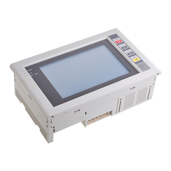
- Page 24 Nomenclature and Functions Section 1-7 NT600M-DF122: Programmable Terminals with Function Keys Display POWER Indicator (green) System Keys Lit while power is on. Used for maintenance of the NT600M, selecting the System Menu, etc. Used during opera- tion for scrolling the screen and RUN Indicator (green) inputting numerical values.
-
Page 25: Table Of Contents
SECTION 2 Switch Settings, Installation, and Wiring This section provides procedures to set hardware switches and install the PT. Switch Settings ............2-1-1 System DIP Switch Settings (SW1) . -
Page 26: Switch Settings
Switch Settings Section 2-1 Switch Settings There are switches to set under the switch cover on the back of the Terminal and also on the Host Interface Unit. For Host Interface Unit switch settings, refer to the Host Interface Unit Operation Manual. 2-1-1 System DIP Switch Settings (SW1) The 8-position DIP switch for system settings is located under the DIP switch... -
Page 27: Mounting System Rom
Switch Settings Section 2-1 Pin no. Setting Content Automatic reset after “Automatic reset” means that, when an error occurs, no error message communications error. will be displayed and the next command will be executed when received. No automatic reset. “No Automatic reset” means that, when an error occurs, an error mes- OFF: Automatic reset. -
Page 28: Screen Data Memory Board Settings And Installation
Notes 1. The PT may not operate properly if the IC socket is not completely se- cured. Be sure to install the System ROM securely. 2. OMRON reserves all copyrights to the programs on the System ROM. Copying these programs is forbidden. - Page 29 Switch Settings Section 2-1 Memory Board. Set these switches to match the memory chip which is in- stalled. NT600M-MP251 Socket The factory-set default set- ting is shown at the left. Middle Bottom SW M2 SW M1 Connector Settings SW M2 SW M1 Screen data memory Bottom...
-
Page 30: Installation Environment
Installation Environment Section 2-2 Place the Screen Data Memory Board on the main rail, push the spacer in the direction of the arrow until it makes a clicking sound, and line the board up with the connector. Rail Spacer Connector Lined up with connector Holding the Memory Board’s installation fitting as shown in diagram A, insert the black latch on the bottom into the hole in the main unit and... -
Page 31: Mounting Position
Installation Environment Section 2-2 • Relative humidity exceeding a range of 35% to 85%. • Corrosive or inflammable gasses. • Strong magnetism. • Excessive dust, salt, or iron dust. • Direct vibration or shock. • Direct sunlight. • Spray from water, oil, or chemicals (the front panel is basically drip-proof). 2-2-2 Mounting Position Mounting Location... -
Page 32: Dimensions
Dimensions Section 2-3 • When installing the Terminal near devices with strong electrical or magnetic fields (such as solenoids), allow a distance of at least 40 mm, more if nec- essary. Solenoid 40 mm min. Solenoid NT600M 40 mm min. Dimensions All dimensions are in millimeters. -
Page 33: Pts With (Dt-Type) And Without (Dn-Type) Touch Panels
Installing the NT600M PT in a Panel Section 2-4 2-3-2 PTs With (DT-type) and Without (DN-type) Touch Panels Installing the NT600M PT in a Panel The NT600M is designed to be inserted in a panel. Install as follows: 1, 2, 3... 1. Cut a hole in the panel in accordance with the recommended dimen- sions shown below. - Page 34 Installing the NT600M PT in a Panel Section 2-4 Insert the PT into the hole from the front of the panel. Use the accessory metal fittings and tool to fasten the PT to the panel surface. Do not use a screwdriver. A screwdriver may damage the fit- tings or the PT.
-
Page 35: Wiring And Connectors
Wiring and Connectors Section 2-5 Wiring and Connectors 2-5-1 Terminal Block The terminal block shown in the following illustration is located on the PT’s rear panel. HOST ALARM OUTPUT INPUT Terminal screws: M4 100 to 240 VAC 50/60 Hz Use crimp-style terminals for wiring. If twisted wires are connected directly, there is a possibility of poor contact or short-circuiting. -
Page 36: Lg And Gr Terminals
Wiring and Connectors Section 2-5 • Insulated Transformer The NT600M has built-in anti-noise features which are sufficient for handl- ing general noise from power lines, but ground noise can be greatly re- duced by supplying power through a 1:1 insulated transformer. The second- ary side of the insulated transformer should be an isolated neutral system. -
Page 37: Alm Output Terminals
RS-232C Interface Connector Section 2-6 Item Content +10% Rated input voltage 24 VDC --15% Input impedance 5.6 kW Input current 4.1 mA typical (at 24 VDC) ON voltage 14.4 V min. OFF voltage 5.0 V max. If host RUN input goes OFF when this terminal is enabled, a host error is dis- played regardless of other conditions and processing is halted. -
Page 38: 12-Key Function Key Units (For Dn-Type Pts)
Tool. Connectors can be put on and taken off even with power on. Applicable Connectors Plug: XM2A-0901 (OMRON) or equivalent. (Cable Side) Hood: XM2S-0911 (OMRON) or equivalent. Recommended Cable AWG28 x 5P IFVV-SB (Fujikura, Ltd.) CO-MA-VV-SB 5P x 28 AWG (Hitachi Cable, Ltd.) Cable Set... - Page 39 Mounting Function Key Units (to DN-type PTs) Section 2-8 3. Attach the rubber packing that comes with the 12-key Function Key Unit. Rubber packing 4. Mount to the panel.
- Page 40 SECTION 3 Initial Operation This section provides an introduction to the operations necessary to use a PT for the first time and to the menus and keys used to control PT operation. Powering Up ............Initialization .
-
Page 41: Powering Up
Initialization Section 3-2 Powering Up When first starting up the system, do not connect the Host Interface Unit to the host. When power is turned on to the PT, either a “Connecting to host” message or the initial screen set by the Support Tool will be displayed. The “Connecting to host”... - Page 42 Initialization Section 3-2 To initialize the screen memory, for example, first access the System Menu by simultaneously pressing the Buzzer Key, Up Key, and Down Key. Then proceed as shown as shown in the following chart. System Menu Refer to Section 6. Select “MAINTENANCE MODE.”...
-
Page 43: Menus
Initialization Section 3-2 3-2-2 Menus The System Menu is called up by using the the system keys during opera- tion. The System Menu can always be displayed regardless of the PT mode. If there is no key input for 10 seconds after the System Menu has been called up, the System Menu will be exited and RUN Mode will return. -
Page 44: Transferring Data To And From The Support Tool
Transferring Data to and from the Support Tool Section 3-3 Error Messages When there is an error in screen data registered in the NT600M, the System Menu will appear before entering RUN Mode, and the error message will be displayed on the bottom line. V1.x System Menu Version no. - Page 45 Transferring Data to and from the Support Tool Section 3-3 When the data transfer begins, the direction of transmission, the type of data being transmitted, and the memory capacity are displayed on the screen. PT ----> Tool Shows direction Transmit Mode Tool ---->...
-
Page 46: Trial Operation
Trial Operation Section 3-4 The following data can be transferred between the NT600M and the Support Tool. Data Support Tool to NT600M NT600M to Support Tool Screen data All screens or one screen All screens or one screen Character string table Numeral table Mark data Display history data (in... - Page 47 SECTION 4 Display Functions This section describes the functions used to create screens and control display attributes on the PT. Functions used to in- put data on-screen are described in Section 5 Input Functions. Data transfer and maintenance functions are described in Section 6 System Menu.
-
Page 48: Character Displays
Character Displays Section 4-1 Character Displays The type, size, and attributes of characters that can be displayed on the NT600M screen are shown on the next page. Character type, size, and at- tributes are set at the time of creation on the Support Tool. When an RS-232C or RS-422A Host Interface Unit is used, coordinates, characters, etc, can be designated with commands from the host in Terminal Mode. -
Page 49: Display Attributes
Display Graphics Section 4-2 4-1-4 Display Attributes Besides the standard display (black characters on a white background), you can designate individual characters as inverse, blinking, or inverse/blinking. Blinking Inverse blinking Note You cannot designate the blinking cycle. 64x characters 16x characters 64x characters 4x characters Normal... -
Page 50: Normal Screen Changes
Continuous Screens Section 4-4 Normal Screen Changes The displayed screen can be changed to another screen by designating the screen number from the host (a Programmable Controller or personal com- puter). The designated screen must have already been created at the Sup- port Tool and downloaded to the NT600M or it must have been placed in ROM, with the Screen Data Memory Board installed. -
Page 51: Overlapping Screens
Overlapping Screens Section 4-5 Example If screen 9 is designated from the host, the content of screen 20 is displayed first. If you press the Down Key, you scroll down to the next screens. Parent screen for consecutive screens Screen no. 9: Screens displayed Screen no. - Page 52 Overlapping Screens Section 4-5 Example If screen 02 is designated from the host, then screens 03, 05, and 08 are dis- played. Parent screen: Screen no. 02 Screen no. 02 is designated by the host. Overlapping screens Screen no. 02: Screen displayed Numbers of child screens: My name is Smith.
-
Page 53: Numeric Displays
Numeric Displays Section 4-6 Numeric Displays A numeral table is stored in the NT600M, and you can display numeric val- ues from the table at designated positions on a screen. In addition, the val- ues in the table can be transferred from the host so that they are renewed each time a new value is transferred. - Page 54 Character Strings Section 4-7 Character Strings This function displays variable character strings on the screen. A character string memory table is stored in the NT600M. By changing, from the host, the memory table values corresponding to the display position, you can update the characters displayed.
- Page 55 Lamps Section 4-9 Bar Graphs If the numeric values that you want to make into a bar graph have been input into the numeral table in advance, then that graph can be displayed simply by designating the screen on which the graph is registered. Just as with nu- meric displays, the graph display is also updated when the contents of the numeral table are updated.
-
Page 56: Graphics Display
Special Controls Section 4-11 Size: Can be freely set with a rectangle or a circle. Number: 128 maximum per screen Display attributes: Lit, blinking Guide characters: Select “yes” or “no.” Lamps set from the host can be turned on and off by either of two methods: number designation or bit designation (when there is no direct connection). -
Page 57: Alarm Output On/Off
Special Controls Section 4-11 Note If there is any key input or transmission while the backlight is off, the back- light will turn on again. 4-11-2 Alarm Output On/Off The output of the ALM OUTPUT terminal, which is located in the terminal block on the rear panel of the NT600M, can be turned ON and OFF from the host. - Page 58 Display Speed Section 4-13 4-11-6 Normal/Inverse Display (LCD-type Only) The display background can be set to either normal or inverse. The normal background is white, and the inverse background is black. Normal display Inverse display Inverse display Normal display 4-12 Terminal Function This function allows you the option of displaying, by transmission on com- mand, the codes (coordinates, type, etc.) of characters and figures you want...
- Page 59 Display Speed Section 4-13 Time it Takes to Display the Same Normal Characters 64x characters 16x characters 9x characters 4x characters Double-height characters Double-width characters/Mark Equal characters Number of characters displayed...
- Page 60 Display Speed Section 4-13 Time it Takes to Display a Variety of Normal Characters 64x characters 16x characters 9x characters 4x characters Double-height characters Double-width characters/Mark Equal characters Number of characters displayed...
- Page 61 SECTION 5 Input Functions This section describes the functions used to input data on-screen. Functions used to create screens and control display attributes on the PT are described in Section 4 Display Functions. Data transfer and maintenance functions are described in Section 6 System Menu.
-
Page 62: On-Screen Switch Inputs
On-screen Switch Inputs Section 5-1 On-screen Switch Inputs DT-type PTs can transmit to the host the input status of touch switches set on screens. A maximum of 64 switches can be set per screen. DN-type PTs can transmit to the host the inputs of 12-key Function Key Units. DF-type PTs can transmit to the host the input status of the function keys located at the bottom of the display. -
Page 63: Creating Touch Switches (Dt-Type Pts Only)
On-screen Switch Inputs Section 5-1 Example 2: Switches Created at Points E, F, and G If switches E and F are turned ON simultaneously in this switch configuration, switch G will also turn ON. Minimum touch switch frame 5-1-2 Creating Touch Switches (DT-type PTs Only) Just as with lamps, touch switches are created and registered with the Sup- port Tool. -
Page 64: Function Keys (Nt600M-Df122)
Inputting Numeric Settings Section 5-2 5-1-3 Function Keys (NT600M-DF122) The NT600M-DF122 is the PT with function keys. DN-type PTs (NT600M- DN-221) can also be provided with function keys by connecting a 12-key Function Key Unit (NT600M-FK210). Function keys Example of Function Key Input Screen Time Setting 56 s 0 CLR +/-... - Page 65 Inputting Numeric Settings Section 5-2 standard screen will be displayed.) For instructions on registering numeric setting screens, refer to the NT-series Support Tool Operation Manual. User-set Screen Example Standard Screen (Screen Attribute: System) (Screen Attribute: User) HOME MENU Tank A Tank B ↑...
- Page 66 Inputting Numeric Settings Section 5-2 Numeric Input Example This example shows numeric input with a user-set screen. The display set- tings made with the Support Tool are as follows: Number of digits displayed: Number of integer digits: Number of decimal digits: Zero suppress: Plus/minus mark display: The following table shows the inputs and the resulting changes in the display.
-
Page 67: Standalone Function
Standalone Function Section 5-3 2) When Touch Switches are Used: When touch switches are used, the cursor moves from area to area accord- ing to the layout of the screen. Thus, in the screen example shown above, the Down Key would move the cursor from numeric setting 2 to numeric set- ting 5. - Page 68 SECTION 6 System Menu This section describes data transfer and maintenance functions. Functions used to create screens and control display at- tributes on the PT are described in Section 4 Display Functions. Functions used to input data on-screen are described in Section 5 Input Functions.
- Page 69 Configuration of System Menu Section 6-1 Configuration of System Menu The System Menu is used to set NT600M system parameters in advance and perform maintenance. With the System Menu you can, in addition to de- termining the NT600M’s status, check switch settings and perform simple I/O checks.
- Page 70 System Menu and Transmit Mode Section 6-2 System Menu and Transmit Mode 6-2-1 Quit To leave the System Menu and return to RUN Mode, select Quit. If no key is pressed for 10 seconds, the PT will automatically return to RUN Mode. SYSTEM MENU Quit Transmit Mode...
- Page 71 System Menu and Transmit Mode Section 6-2 Setting History Data (1) When creating screens with the Support Tool, use screen attribute desig- nations to register history attributes and messages (within 24 characters) for the screens you want to save in the history. (2) Whenever the screen number registered for history attributes is desig- nated by the host, the occurrence and message are saved in memory.
- Page 72 System Menu and Transmit Mode Section 6-2 • Up to 48 items of registered data can be displayed on a screen. • If not all of the record data shows on the screen, then use the Down Key to scroll down. •...
- Page 73 System Menu and Transmit Mode Section 6-2 (1) DT-type PT with LCD Display I/O CHECK MENU Quit Function Key Touch Switch Comm. Check LCD Display Buzzer (2) DT-type PT with EL Display I/O CHECK MENU Quit Function Key Touch Switch Comm.
- Page 74 System Menu and Transmit Mode Section 6-2 Function Key Check (DN-type PTs) The operation of the function keys can be checked. Press a function key. If the number of that key is displayed in reverse video on the screen, then it is operating properly.
- Page 75 System Menu and Transmit Mode Section 6-2 a 12-key Function Key Unit is connected, F1 through F12 correspond to IN0 through IN11. To return to the I/O Check Menu, press the Buzzer Key, Up Key, and Down Key simultaneously. Lamp Output Check When “Lamp Output”...
- Page 76 System Menu and Transmit Mode Section 6-2 To return to the I/O Check Menu, press the Buzzer Key, Up Key, and Down Key simultaneously. Tool Interface Check Data transmitted from the Support Tool is displayed in hexadecimal. If any numeral is displayed, then the interface is operating properly. If no numerals are displayed, then there is a Support Tool operation error, communications cable error, or communications hardware error.
- Page 77 System Menu and Transmit Mode Section 6-2 PT Settings Next Page Memory Type Memory Size 128 KB Host RUN Disable Mode Changes Memory type and memory size are displayed only after the screen memory has been initialized. If it has not been initialized, then “N.A.” is displayed. 2) DN-type PTs PT Settings Next Page...
- Page 78 Memory Switch Settings Section 6-3 Initializing Screen Memory In order to initialize screen memory, for example, first select “Init. Memory” from the Maintenance Menu. The Memory Initialization Menu will then be dis- played, offering several choices of memory to initialize. Screen data Screen data and all kinds of set values Memory table data...
- Page 79 Memory Switch Settings Section 6-3 Select “Memory SW” from the Maintenance Mode Menu. MAINTENANCE MODE MENU Quit Display History I/O Check PT Settings Initialize Memory Memory SW Select one Liquid Crystal Display Type Move the cursor to the item that is to be set and press the Enter Key. Each time that it is pressed, the set value will change.
- Page 80 Memory Switch Settings Section 6-3 Item Setting Contents Display (LCD type) Normal The screen display is normal. Reverse video The screen is displayed with dark and light reversed. Residual image elimination 10 min If no key input (see note 1) or command (see note 2) is received for 10 function (EL type) minutes while a screen is being displayed, the screen turns off.
- Page 81 Memory Switch Settings Section 6-3 Display Examples Depending on the setting of the resume function, the display at the time of pow- ering up will be as follows: Display After Power is Turned Back On or After Reset Display at Beginning Display just Prior to Power 9999 When resume function...
- Page 82 SECTION 7 Online Transfer This section describes transferring screens online to and from the host computer. This function can only be used with RS-232C and RS-422A Host Interface Units. For details on Host Interface Unit commands, refer to information on on- line transfers in the Host Interface Unit Operation Manual.
- Page 83 PT to Host Section 7-2 Host to PT • Screen data can be transferred along with screen numbers. Set the desired screen number. If you set a screen number which is identical with one al- ready registered in the NT600M, then the screen data for that number will be overwritten.
- Page 84 PT to Host Section 7-2 Relationship Between Just as when transferring data from the Support Tool, on-line transfer writes data On-line Transfer and the directly from the host to the screen memory. The display contents, therefore, are Resume Function affected by the resume function. Display After Data is Received Directly Display After Data is Received from Host Reception...
- Page 85 SECTION 8 Maintenance and Inspection This section provides troubleshooting and basic maintenance methods, including battery replacement. Checking Operation ............Changing the Lithium Backup Battery .
-
Page 86: Checking Operation
240 VAC. A fuse is blown. Contact your OMRON representative. Screen does not display. It is waiting for a command from the Transfer a command from the host. Screen data host, or there is no screen data, or should be registered at the Support Tool in advance. -
Page 87: Maintenance And Inspection
Maintenance and Inspection Section 8-3 2. Even if the BAT LOW indicator does not light, the battery should be re- placed after five years. Replacing the Battery 1, 2, 3... 1. Turn the power off. If the power has not been on, turn it on for at least one minute and then turn it of again before replacing the battery. -
Page 88: Precautions When Cleaning The Pt Screen
• When you discover a defective Terminal and replace it, check again to be sure that the problem was actually with the Terminal. • When returning a defective Terminal for service, please describe the prob- lem in as much detail as possible. Send the Terminal to the OMRON offices closest to you. 8-3-3 Precautions When Cleaning the PT Screen If the NT600M screen gets dirty, it will become hard to read. -
Page 89: Run Mode Function Configuration
RUN Mode Function Configuration Section 8-4 RUN Mode Function Configuration RUN Mode Chart This chart shows the measures to be taken in response to an error which occurs in RUN Mode. Power on Screen Error message check Normal DIP Switch Check Screen Screen display... - Page 90 RUN Mode Function Configuration Section 8-4 I/O check Normal PC: Programmable Controller PC mode check Continue Mode Stop Mode I/O Check Error Has Occurred Remedy Check I/O settings of remote devices. Operation Check the PC’s I/O Units. Stopped Once only when power is turned on. Power supply check...
- Page 91 Appendix A Standard Models RS-232C Cable for Connecting Devices (CV500-CN228) +150 2 ,000 - -0 Note The personal computer end of the CV500-CN228 Connecting Cable is a 25-pin D-sub male con- nector. To connect to an IBM PC/AT or compatibles, a 9-pin or 25-pin D-sub female adapter is required.
- Page 92 Standard Models Appendix A NT600M-KBA02 Dimensions 254.4+0.2 13.2 327.4+0.2 Protective Sheet NT600M-KBA11 (for NT600M-DT/DN/DF122) NT600M-KBA12 (for NT600M-DT/DN211) The protective sheet protects the display screen from dirt and scratches, and eliminates reflection and glare. (The back side of the sheet has a sticky surface. Peel the paper off of the back and attach the sheet.) Protective film Protective sheet Display screen...
- Page 93 Appendix B Specifications General Specifications Item Specifications Power supply voltage 100 to 240 VAC Allowable power supply volt- 85 to 264 VAC, 50/60 Hz age range Power consumption 40 VA max. Insulating resistance Between AC terminal block and GR: 20 MW min. (at 500 VDC) Dielectric strength Between AC terminal block and GR: 2,300 VAC at 50/60 Hz for 1 min...
- Page 94 Specifications Appendix B Characteristics Display Specifications Item Specifications LCD-type display: Dot matrix STN liquid crystal display device (9.5 inches equivalent) (NT600M-Dj122) No. of dots: 640 x 400 Effective display area: 206 mm x 130 mm Angle of vision: Up 20°; down 35°; right/left ±30° Life expectancy: 50,000 hrs min.
- Page 95 Specifications Appendix B Display Capacity Item Specifications Terminal mode Characters, numeric values, and graphics designated by the host are displayed (RS-232C or RS-422A interface required). Display Character Displays optional characters (screen number designation). elements Graphics Polylines (broken continuous line) and circles String displays Maximum 256 total, 50 places per screen and 40 bytes per string Numeral displays Maximum 256 total, 50 places per screen, 8-digit display...
- Page 96 Specifications Appendix B Special Features Item Specifications Alarm output Relay output on rear terminal block; NO contact. Rating: 1 A at 24 VDC or 0.5 A at 100 VAC, with resistance load Output condition: NO Contact (Closes when a command is received from the host or when there is a screen displayed with an alarm-ON specification.) Host RUN input Photocoupler input on rear terminal block.
- Page 97 Appendix C Memory Check Table This table shows the amount of memory required for creating various kinds of screen data. It can be used a stan- dard for selecting screen memory. Data Item Without direct With direct Remarks connection connection (Unit: byte) (Unit: byte) Tables, error screens,...
- Page 98 Appendix D Special Characters English Character Codes Pin 2 of SW2 must be ON to enable English language messages to use the following codes. Example: Hex code is represented by 30, decimal code by 48, and character by 0. Code 20 and 32 in the table represents a space, as indicated by “SP.” ‘...
- Page 99 Index Numbers types available, 4 display history, 63 controlling from host, 49 12-key Function Key Units, checking, 67 initializing, 70, 71 A- -B E- -F abbreviations, 5 error messages, 35 alarms, controlling from host, 49 Expansion Mode, 63 ALM OUTPUT terminals, 27 Function Key Units, 9 ASCII Unit, 11 function keys, 14, 56...
- Page 100 Index screen memory, initializing, 70 screens changing, 42 maintenance, inspection, 81 continuous screens, 42 Maintenance Mode, 63 examples, 41 manuals, 5 maximum limit, 7 maximum registered, 4 memory, initializing, 32 overlapping screens, 43 memory capacity, 7 transferring online, 76 memory chips, 6 specifications, 87 memory switch settings, 71 standalone function, 4, 59...
- Page 101 Revision History A manual revision code appears as a suffix to the catalog number on the front cover of the manual. Cat. No. V002-E1-3 Revision code The following table outlines the changes made to the manual during each revision. Page numbers refer to the previous version.