Rotel RDV-985 Technical Manual
Hide thumbs
Also See for RDV-985:
- Technical manual (47 pages) ,
- Owner's manual (30 pages) ,
- Owner's manual (30 pages)
Advertisement
Quick Links
T echnical
Manual
Table of Contents
Specification......................................1
Information........................................2~17
Block Diagrams.................................18~22
Schematic Diagram ..........................23~33
PCB Assembly..................................34~36
Parts List...........................................37~47
Specifications
General
Readable Discs:
Video Fomat:
Video Output
VIDEO OUT (pin jack):
S-VIDEO OUT (S jack):
Y Output:
C Output:
Horizontal Resolution:
Signal to Noise Ratio:
Audio Output
ANALOG OUT (pin jack):
DIGITAL OUT (optical):
Audio Characteristics
Frequency Response:
CD: (sampling frequency 44.1 kHz):
DVD (sampling frequency 48 kHz):
DVD (sampling frequency 96 kHz):
Dynamic Range:
16 bit:
20 bit:
24 bit:
Wow and Flutter:
Total Harmonics Distortion:
Physical
Power Requirements:
USA Version:
European Version:
Power Consumption:
Weight:
Dimensions (W x H x D):
THE ROTEL CO., LTD.
SHINSEN-BLD. 4F 10-10 SHINSEN-CHO, SHIBUYA-KU,
TOKYO 150-0045, JAPAN
All manuals and user guides at all-guides.com
Quality Uncompromised
DVD VIDEO, Audio CD, VIDE CD, SUPER VIDEO CD
PAL or NTSC selectable
1.0 Vp-p (75 ohms)
1.0 Vp-p (75 ohms)
286 mVp-p (75 ohms)
500 Lines
65 dB
2.0 Vrms (10 kohms)
- 21 to -15 dBm (peak)
2 Hz to 20 kHz
2 Hz to 22 kHz
2 Hz to 44 kHz
More than 100 dB
More than 108 dB
More than 108 dB
Unmeasurable (less than ±
Less than 0.002%
AC 120V, 60 Hz
AC 230V, 50 Hz
23 W (POWER ON), 2 W (STANBY mode)
4.7 kg (10.4 lbs)
445 x 112 x 338 mm
17
x 4
x 13
inch
1/2
7/16
5/16
®
DVD PLAYER
RDV-985
0.002%)
Serial. NO.
Beginning
Y-356A-0109/W
Advertisement

Related Manuals for Rotel RDV-985


Summary of Contents for Rotel RDV-985
- Page 1 23 W (POWER ON), 2 W (STANBY mode) Weight: 4.7 kg (10.4 lbs) Dimensions (W x H x D): 445 x 112 x 338 mm x 13 inch 7/16 5/16 THE ROTEL CO., LTD. Serial. NO. SHINSEN-BLD. 4F 10-10 SHINSEN-CHO, SHIBUYA-KU, Beginning TOKYO 150-0045, JAPAN Y-356A-0109/W...
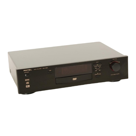
- Page 2 All manuals and user guides at all-guides.com Appearance...
-
Page 3: Main Adjustment
All manuals and user guides at all-guides.com Main Adjustment Adjustment and confirmation matter (1) Auto adjustment method If microprocessor (IC401, IC402, IC714, IC716) or servo board (LEA10047) is replaced, initialize the DVD player in the following matter: ref. separate sheet. (2) Confirmation of DVD RF level "12"... - Page 4 All manuals and user guides at all-guides.com (4)Flap adjustment of the Pick-up guide shaft Attention !! RDV-985 is adjusted from issue machine because of the FL display on the way. Please go in the adjustment method before changes according to the following procedures. Mode...
- Page 5 All manuals and user guides at all-guides.com Confirmation after adjustment. Confirm to reproduce video CD and CD after the DVD test disc is adjusted and to find abnormality. Fig.2 (5) About keeping the disc As for the DVD test disc, plane accuracy is demanded.Please note the keeping place on the disc. Please do not put the disc directly on the work desk etc.
-
Page 6: Check Points For Each Error
All manuals and user guides at all-guides.com Check points for each error (1) Spindle start error *Defective spindle motor Are there 10ohms resistance between each pin of CN101 "29~31"? (The power supply is turned off and measured.) *Hall element: Is sine wave output between CN101 "23" and "24", between "25" and "26", and between "27"... - Page 7 All manuals and user guides at all-guides.com (3) Traverse movement NG * For automatic adjustment, traverse movement occurs only when the position is changed to retry judging the disc type after the 1st judgment resulted in an error. Therefore, traverse movement rarely occurs because, in most cases, disc judgment at the current position (1st time judgment) is executed successfully.
- Page 8 All manuals and user guides at all-guides.com (6) Spindle CLV NG * When the spindle cannot be shifted to CLV Servo, does not become "H" between IC301 "69" and IC201"37". * IC201 Is signal output from CN103 "1" (RFOP)? * IC201 Is signal output from CN103 "11" (DSLIP)? * IC201 Is signal output from CN103 "6"...
- Page 9 All manuals and user guides at all-guides.com (9) Neither picture nor sound is output * Cannot search a) Can the feed system be driven? Chec k the waveform of TRSDRV signal (R273). --- Waveform between R274 and C271. Search results in a change of duty (three v alues with 2.5V at the center) (The figure is e...
- Page 10 All manuals and user guides at all-guides.com (10) Picture is distorted or abnormal sound occurs at intervals of several seconds. Does JITOUT change periodically? Some system other (2V or more in peak than servo may be value, except defective. during kick) Feed system is defective (drive gain is defective: too large).
-
Page 11: Precautions For Service
All manuals and user guides at all-guides.com Precautions for Service Handling of Traverse Unit and Laser Pickup 1. Do not touch any peripheral element of the pickup or the actuator. 2. The traverse unit and the pickup are precision devices and therefore must not be subjected to strong shock. - Page 12 All manuals and user guides at all-guides.com Troubleshooting 1.Power-on processing Connect to outlet. F901 P.STAND-BY Return to A Replace Does fuse is blown indicating lamp and recheck. F901. the lamp lights up? goes out when Micro- POWER switch of computer remote control Volume.
- Page 13 All manuals and user guides at all-guides.com 2. Power Supply Volume With all the wiring removed, check unit power board. (1) Remove all flat wires and wire assemblies which are connected to CN801, CN805, CN806. (2) Short -circuit CN805"4" (POWER ON:B168) and "5" (B5V:B167). (Set each regulator to ON.) The load resistance is connected between CN805"5"(B5V:B167) and "8,9"(D.GND:B164).
- Page 14 All manuals and user guides at all-guides.com 4. Microcomputer Volume Processing of Each Microcomputer IC714 System microcomputer (sub-microcomputer) After powering on, this microcomputer is continuously activated to control keys and remote control signals. According to key operations or remote control signals, it controls (turns on/off) the power for LSIs including IC401 (main microcomputer) and the audio/video output circuit.
-
Page 15: Audio Volume
All manuals and user guides at all-guides.com 5. Audio Volume Power to Power Supply supplied correctly Volume to each IC? IC702 are supplied power from IC718. Check I/O voltage of IC718. Is sound signal output from J702 (pin jack)? Approx . - Page 16 All manuals and user guides at all-guides.com 6. Video Volume Power to Power Supply +5V power for video section is supplied correctly Volume supplied from IC654. to each IC? Check I/O voltage of IC654. Is video Check the insertion of Is video signal output from signal output from...
- Page 17 All manuals and user guides at all-guides.com 7.Servo volume Press from A "OPEN/CLOSE" *only two layer disc (DVD) Is the jump between layers OK? Is the opening to OPEN/CLOSE (16) Jump between operation of Operation Section layers NG TRAY normal? After "FL"...
- Page 18 All manuals and user guides at all-guides.com Block diagrams (DVD SERVO CONTROL Section)
- Page 19 All manuals and user guides at all-guides.com Block diagrams (DC REGURATOR Section)
-
Page 20: Component Video Out
All manuals and user guides at all-guides.com Bloc k dia grams (VIDEO OUT & A UDIO OUT) CN601 LVA10054-A2 IC601 Pr,Pb AMP 4MHz LPF NJM2267D J601 L601 QQR0712-001 TO CN702 4MHz LPF LVA10047 COMPONENT L602 (DVD SERVO VIDEO OUT QQR0712-001 CONTROL 2) VIDEO SIGNAL IN 6MHz LPF... - Page 21 All manuals and user guides at all-guides.com RDV-985 Block diagrams (SYSTEM CONTROL & FL DRIVER Section) LVA10054-A1 CN703 +5V REG. KEY MATRIX KEY00~KEY03 IC718 83,84,86~92 KEYI0~KEYI5 RESET IC717 TO CN801 OF EEPR OM RESET LVA10053-A1 IC715 PST574CMT - X NJM78M05...
- Page 22 All manuals and user guides at all-guides.com Meno...
- Page 23 All manuals and user guides at all-guides.com RDV-985 DVD Servo Control 1 K371 BLOCK A BLOCK B GNAL BLOCK D BLOCK C DIGT AL DAT A SIGNAL...
- Page 24 All manuals and user guides at all-guides.com RDV-985 RDV-985 Block A to Block B to Block C...
- Page 25 All manuals and user guides at all-guides.com RDV-985 Block B to Block A to Block D...
- Page 26 All manuals and user guides at all-guides.com RDV-985 Block C to Block A to Block D...
- Page 27 All manuals and user guides at all-guides.com RDV-985 Block D to Block B to Block C DIGTAL DATA SIGNAL...
- Page 28 All manuals and user guides at all-guides.com RDV-985 RDV-985 DVD Servo Control 2 ol 2 HY57V161610DTC8 HY57V161610DTC8 DIGTAL DATA SIGNAL VIDEO SIGNAL AUDIO SIGNAL...
- Page 29 All manuals and user guides at all-guides.com RDV-985 Display...
- Page 30 All manuals and user guides at all-guides.com RDV-985 RDV-985 RDV-985 RDV-985 RDV-985 RDV-985 RDV-985 RDV-985 Power Supply RDV-985 750K 750K QNZ0136-001Z QMF51U1-1R6-S 1000PF/AC250V 0.47(2W) 120uF/400V LE40597-001A 4700PF/AC250V 68K(2W) PC123F...
- Page 31 All manuals and user guides at all-guides.com RDV-985 Video & Jac AUDIO SIGNAL VIDEO SIGNAL...
- Page 32 All manuals and user guides at all-guides.com RDV-985 RDV-985 AUDIO SIGNAL...
- Page 33 All manuals and user guides at all-guides.com RDV-985 Connection...
- Page 34 All manuals and user guides at all-guides.com RDV-985 Printed circuit board Power supply board Display board...
- Page 35 All manuals and user guides at all-guides.com RDV-985 CPU & Video & Jack board S601 NTSC/PAL SW...
- Page 36 All manuals and user guides at all-guides.com Servo control board (BOTOM SIDE) (TOP SIDE) R374...
-
Page 37: Parts List
All manuals and user guides at all-guides.com PARTS LIST [RDV-985] * All printed circuit boards and its assemblies are not available as service parts. - Page 38 All manuals and user guides at all-guides.com Parts List 1/8 SYMBOL PARTS NO. DESCRIPTION SYMBOL PARTS NO. DESCRIPTION POWER SUPPLY, FL DISPLAY BOARD LVA10053 D842 1SS199-02-T2 SI DIODE BK901 E409182-001SM GRAND TERMINAL D844 1SS199-02-T2 SI DIODE C832 QER61AM-476Z ELECTROLYTIC CAPACITOR 10V47uF D845 1SS199-02-T2 SI DIODE...
- Page 39 All manuals and user guides at all-guides.com Parts List 2/8 SYMBOL PARTS NO. DESCRIPTION SYMBOL PARTS NO. DESCRIPTION R803 QRE141J-472Y CARBON RESISTOR 4.7K 1/4W C603 QETN1AM-108Z ELECTROLYTIC CAPACITOR 10V1000uF R804 QRE141J-472Y CARBON RESISTOR 4.7K 1/4W C604 QETN1AM-108Z ELECTROLYTIC CAPACITOR 10V1000uF R805 QRE141J-472Y CARBON RESISTOR 4.7K 1/4W...
- Page 40 All manuals and user guides at all-guides.com Parts List 3/8 SYMBOL PARTS NO. DESCRIPTION SYMBOL PARTS NO. DESCRIPTION C765 QCF11HZ-473 CERAMIC CAPACITOR 0.047uF R1005 QRE141J-103Y CARBON RESISTOR 10K 1/4 CN601 VMC0075-010N 10P PLUG ASSY TO MAIN R1006 QRE141J-273Y CARBON RESISTOR 27K 1/4 CN701 QGF1016C1-35 FFC/FPC CONNECTOR TO MAIN...
- Page 41 All manuals and user guides at all-guides.com Parts List 4/8 SYMBOL PARTS NO. DESCRIPTION SYMBOL PARTS NO. DESCRIPTION R742 QRE141J-471Y CARBON RESISTOR 470 1/4 C120 NCB31CK-104X CERAMIC CAPACITOR 0.1uF R743 QRE141J-471Y CARBON RESISTOR 470 1/4 C121 NCB21CK-334X CERAMIC CAPACITOR 0.33uF R744 QRE141J-471Y CARBON RESISTOR 470 1/4...
- Page 42 All manuals and user guides at all-guides.com Parts List 5/8 SYMBOL PARTS NO. DESCRIPTION SYMBOL PARTS NO. DESCRIPTION C253 NCB31CK-104X CERAMIC CAPACITOR 0.1uF C501 NCB31CK-104X CERAMIC CAPACITOR 0.1uF C254 NCB31CK-104X CERAMIC CAPACITOR 0.1uF C502 NCB31CK-104X CERAMIC CAPACITOR 0.1uF C255 NEA70JM-226X ELECTROLYTIC CAPACITOR 6.3V22uF C503 NCB31CK-104X...
- Page 43 All manuals and user guides at all-guides.com Parts List 6/8 SYMBOL PARTS NO. DESCRIPTION SYMBOL PARTS NO. DESCRIPTION CN503 QGA2001C2-10X W TO B CONNECTOR VIDEO K559 NQR0007-002X FERRITE BEADS C.M. D201 1SS355-X DIODE C.M. K561 NQR0007-002X FERRITE BEADS C.M. D202 1SS355-X DIODE C.M.
- Page 44 All manuals and user guides at all-guides.com Parts List 7/8 SYMBOL PARTS NO. DESCRIPTION SYMBOL PARTS NO. DESCRIPTION R131 NRSA63J-0R0X MG RESISTOR 0 R271 NRSA63J-243X MG RESISTOR 24K R151 NRSA63J-0R0X MG RESISTOR 0 R272 NRSA63J-103X MG RESISTOR 10K R152 NRSA63J-0R0X MG RESISTOR 0 R273 NRSA63J-103X...
- Page 45 All manuals and user guides at all-guides.com Parts List 8/8 SYMBOL PARTS NO. DESCRIPTION SYMBOL PARTS NO. DESCRIPTION R505 NRSA63J-330X MG RESISTOR 33 R582 NRSA3J-0R0X MG RESISTOR 0 R506 NRSA63J-330X MG RESISTOR 33 R583 NRVA63D-471X CMF RESISTOR 470 R507 NRSA63J-330X MG RESISTOR 33 R584 NRVA63D-103X...
- Page 46 All manuals and user guides at all-guides.com DVD Mechanism Unit and Parts List Block No. M2MM FLM-V3 FOR MODULE BOARD MECHA LOADING BOARD REF. PARTS NO. PARTS NAME REMARKS SUFFIX Chassis GMVMD3270 Tray GMVMD3265 Pulley gear GMVDG1308 Drive gear 1 GMVDG1309 Drive gear 2 GMVDG1310...
- Page 47 All manuals and user guides at all-guides.com DVD Mechanism Unit and Parts List Block No. M2MM FML-V3 FOR STEPPING MOTOR FOR MODULE BOARD FOR SPINDEL MOTOR REF. PARTS NO. PARTS NAM E REMARKS SUFFIX Spindle FFC GMVWJ1277 Spindle motor unit GMVEM0665 Stepping motor unit GMVEM0666...