Rangemaster Professional+ FX 90 Induction User's Manual & Installation Instructions
Hide thumbs
Also See for Professional+ FX 90 Induction:
- User's manual & installation instructions (40 pages) ,
- User's manual & installation instructions (44 pages)
Table of Contents
Advertisement
Quick Links
Advertisement
Table of Contents

Related Manuals for Rangemaster Professional+ FX 90 Induction


Summary of Contents for Rangemaster Professional+ FX 90 Induction
- Page 1 USER GUIDE & INSTALLATION INSTRUCTIONS Professional+ FX 90 Induction U110127 - 10...
- Page 2 Terms & Conditions 1. This is my Rangemaster is open to residents of UK mainland only, aged 18 years & over. 2. All entries should be submitted to the advertised e-mail address, or Rangemaster UK Facebook, Instagram or Twitter page using the advertised hashtag &...
-
Page 3: Table Of Contents
Contents Before you start... Cooking tips Personal safety Cleaning your cooker Electrical connection safety Troubleshooting Peculiar smells Ventilation Installation Maintenance Safety requirements and regulations Induction and ceramic care Provision of ventilation Oven care Location of cooker Hob care Positioning the cooker Cooling fan Moving the cooker Cooker care... -
Page 5: Before You Start
Before you start... Your cooker should give you many years of A long term cooking process has to be • trouble-free cooking if installed and operated supervised from time to time. A short term correctly. It is important that you read this cooking process has to be supervised section before you start. -
Page 6: Peculiar Smells
cooker control unit incorporating a double Peculiar smells pole switch, having a contact separation of at When you first use your cooker it may give off least 3 mm in all poles. an odour. This should stop after use. Read the instructions before installing or using Before using for the first time, make sure that this appliance. -
Page 7: Induction And Ceramic Care
AGA Rangemaster Induction Pots Foods for frying should be as dry as and Pans. If you decide to purchase an •... - Page 8 Fig. 1.1, are avoided. This type of pan Fig. 1.1 construction can significantly reduce the lifetime and performance of your induction cook top. Take care when touching the marked • cooking areas of the hob. Use adequately sized pans with flat •...
-
Page 9: Oven Care
Take care NOT TO PLACE HOT LIDS onto Use oven gloves to protect your hand from • • the Hob surface (Fig. 1.5). Lids that have potential burns. been used to cover a hot pan can “stick” Cooking high moisture content foods can •... -
Page 10: Hob Care
Hob care Fig. 1.7 NEVER allow anyone to climb or stand on • the hob. DO NOT use the hob surface as a cutting • board. ArtNo.090-0007 90 Ceramic: DO NOT leave utensils, foodstuffs or oven steam out the back •... -
Page 11: Cleaning
NEVER store flammable materials in the Cleaning • drawer. This includes paper, plastic and Isolate the electricity supply before • cloth items, such as cookbooks, plastic carrying out any thorough cleaning. Allow ware and towels, as well as flammable the cooker to cool. liquids. -
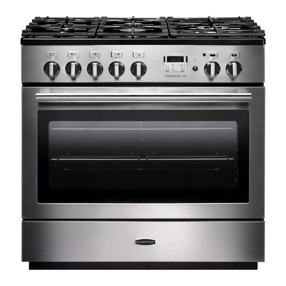
Page 12: Overview
Overview DocNo.023-0015 - Overview - 90 induction SC - Prof+ FX Fig. 2.1 Professional + FX ArtNo.273-0003 - 90IN - Prof+ annotated The induction cooker (Fig. 2.1) has the following features: Fig. 2.2 5 induction cooking zones A control panel A multi-function oven A storage drawer The Hob... -
Page 13: Pan Detector
The very best pans have bases that are very slightly curved up when cold (Fig. 2.3). If you hold a ruler across the bottom Fig. 2.3 you will see a small gap in the middle. When they heat up the metal expands and lies flat on the cooking surface. -
Page 14: Residual Heat Indicator, H
Residual Heat Indicator, H Automatic heat-up time at Power level 100% (min:sec) After use, a cooking zone will remain hot for a while as heat 0:48 dissipates. When a cooking zone is switched off the residual heat indicator symbol [H ], will appear in the display. This 2:24 shows that the cooking zone temperature is above 60 °C and 3:50... -
Page 15: Low Temperature Setting, L1/L2
Low Temperature Setting, L1/L2 A & B linked Fig. 2.8 Each cooking area is equipped with 2 low temperature settings: • L1 will maintain a temperature of about 40 °C – ideal for gently melting butter or chocolate. • L2 will maintain a temperature of about 90 °C – ideal for simmering (bring the pan to the boil and then select L2 to keep soups, sauces, stews, etc at an optimal simmer). -
Page 16: Multifunction Oven
Multifunction Oven Fig. 2.10 The oven is a multi-function oven (Fig. 2.9).As well as the ArtNo.270-0025 oven fan and fan element, they are fitted with two extra Proplus MF oven annotated heating elements, one visible in the top of the oven and the second under the oven base. - Page 17 Fanned Grilling (C) This function operates the fan while the top element n WARNING! n is on. It produces a more even, less fierce heat than a Take great care when removing the divider not to scratch conventional grill. For best results place the food to the inner glass door surface.
-
Page 18: Energy Saving Panel
The Browning and Base Heat functions are useful additions to your oven, giving you flexibility to finish off items to Fig. 2.14 perfection. With use, you will soon realise how these ArtNo.270-0026 functions can combine to extend your cooking skills. Proplus MF oven controls (2) Energy Saving Panel The oven has a divider feature (Fig. -
Page 19: Accessories
Accessories Fig. 2.17 Fig. 2.18 Oven Shelves ArtNo.326-0014 - Cradle rack (Falcon) Each oven is supplied with: ArtNo.326-0013 - Full capacity shelf (Falcon) • Two full capacity shelves (Fig. 2.17) • Grill pan tray support (Fig. 2.18) Fig. 2.19 Fig. 2.20 •... -
Page 20: 3. 2 Button - Rotary Clock
3. 2 Button - rotary clock The clock must be set to the time of day before the oven Fig. 3.1 ArtNo.300-0005 2BC will work. minute minder setting Setting the Clock Once the cooker is connected and switched on, the display will start to flash. - Page 21 To stop the oven at a specific time of day Fig. 3.5 You have set the required temperature and function mode and you would like the oven to automatically stop. TOP TIP Make a note of the current time so you do not forget. Turn the Timer (A) knob to the Stop Time (G) setting.
- Page 22 To start and stop the oven automatically Fig. 3.9 The timer allows you to automatically start and stop by a combination of the length of the cooking time and the stop time. Giving you the flexibility to cook casseroles etc while you are out.
-
Page 23: Cooking Tips
Cooking tips Cooking with a multifunction oven General oven tips Remember: not all modes are suitable for all food types. The The wire shelves should always be pushed firmly to the back oven cooking times given are intended for a guide only. of the oven. -
Page 24: Cleaning Your Cooker
Cleaning your cooker Isolate the electricity supply before carrying out any major Fig. 5.1 cleaning. Allow the cooker to cool. NEVER use paint solvents, washing soda, caustic cleaners, biological powders, bleach, chlorine based bleach cleaners, coarse abrasives or salt. DO NOT mix different cleaning products – they may react together with hazardous results. - Page 25 edge – some oven cleaners can damage the seal. Removing the oven door outer panel Remove the strip by gently pulling both ends to The outer door panel can be removed so that the inside of release the hooks holding it in place. the glass can be cleaned.
-
Page 26: Troubleshooting
Troubleshooting DocNo.050-0001 - Troubleshooting - Induction GENERIC Interference with and repairs to the hob MUST NOT The cooling fan be carried out by unqualified persons. Do not try The induction hob incorporates a cooling fan. This cooling to repair the hob as this may result in injury and fan is active when either the grill or the oven(s) are on. - Page 27 The oven light is not working Fig. 6.1 The bulb has probably blown. You can buy a replacement bulb (which is not covered under the guarantee) from most electrical stores. Ask for a 40 W – 230 V halogen lamp (G9) (Fig.
-
Page 28: Installation
INSTALLATION Check the appliance is electrically safe when you have finished. Installation Dear Installer any other purpose could invalidate any warranty or liability claim. Before you start your installation, please complete the details You will need the following equipment to complete the below, so that, if your customer has a problem relating to cooker installation satisfactorily: your installation, they will be able to contact you easily. -
Page 29: Positioning The Cooker
INSTALLATION Check the appliance is electrically safe when you have finished. Positioning the cooker Fig. 7.1 The diagrams show the minimum recommended distance from the cooker to nearby surfaces (Fig. 7.1 and Fig. 7.2). The cooker should not be placed on a base. 75 mm min 650 mm min 75 mm min... -
Page 30: Removing The Oven Door
INSTALLATION Check the appliance is electrically safe when you have finished. Removing the oven door Fig. 7.3 To remove the oven door, open the door fully. Swivel the locking ‘U’ clips forward to the locking position (Fig. 7.3). Grip the sides of the door, lift upwards and then slide the door forwards (Fig. -
Page 31: Fitting The Stability Bracket Or Chain
INSTALLATION Check the appliance is electrically safe when you have finished. Fitting the stability bracket or Fig. 7.7 chain Stability chain Unless otherwise stated, a cooker using a flexible gas connector must be secured with a suitable stability device. Suitable stability devices are shown in Fig. 7.7, Fig. 7.8 and Fig. -
Page 32: Electrical Connection
INSTALLATION Check the appliance is electrically safe when you have finished. Electrical connection Current Operated Earth Leakage Breakers The cooker must be installed by a qualified electrician, in The combined use of your cooker and other domestic accordance with all relevant British Standards/Codes of appliances may cause nuisance tripping, so we recommend Practice (in particular BS 7671), or with the relevant national that the cooker is protected on an individual RCD (Residual... -
Page 33: Final Checks
INSTALLATION Check the appliance is electrically safe when you have finished. Final Checks Fig. 7.12 Hob Check Check each cooking zone in turn. Be sure to use pans of the correct size and material. Oven Check ArtNo.281-0026 - Front plinth NOTE: Make sure you have set the clock (see ‘Section 2’). -
Page 34: Fitting The Drawer
INSTALLATION Check the appliance is electrically safe and gas sound when you have finished. Fitting the drawer Removing the drawer... -
Page 35: Circuit Diagram
Circuit diagram Oven r (f) Clear boots r (f) Red boots r (f) Red boots Fan output from hob Black boots Terminal 1 on hob Terminal 2 on hob Terminal 4 on hob Terminal 5 on hob Terminal 6 on hob The connections shown in the circuit diagram are for single-phase. - Page 36 Induction Hob Earth On Terminal Block N(6) On Terminal Block N(4) INDUCTION UNIT DISPLAY L(2) L(3) w/br w/br INTERFACE On Terminal Block BOARD w/br w/br w/br Code Description Code Colour w/br Left-hand front element White or brown Left-hand back element Right-hand back element Right-hand front element Centre element...
-
Page 37: Technical Data
DATA BADGE LOCATION: Inside base drawer of cavity. Remove the drawer. COUNTRY OF DESTINATION: GB, IE. Connections Electric 230 / 400 V ~ 50 Hz 3N Dimensions Model Professional+ FX 90 Induction Overall height 905 minimum mm 930 maximum mm Overall width 900 mm Overall depth... - Page 38 Professional + FX 90 Induction 645 DEPTH INCLUDING HANDLES 608 DEPTH EXCLUDING HANDLES...
- Page 39 Hotplate efficiency data Brand Rangemaster Model Identification Professional+ FX Size 90 Single Cavity Type Induction Type of Hob Induction Number of electric zones Zone 1 - Ø cm 18.5 Heating Technology Energy Consumption (ECElectric cooking) - Wh/kg Zone 2 - Ø cm 15.5...
- Page 40 Oven data Brand Rangemaster Model identification Professional+ FX Type of oven Electric Mass Number of cavities Single Cavity Efficiency Fuel type Electric Cavity type Multifunction* *Drop Down Door Power - conventional 2.75 Power - forced air convection Volume Litres Energy consumption (electricity) - conventional kWh / cycle 1.16...
- Page 41 NOTES...
- Page 42 NOTES...
- Page 43 • Has not been repaired by persons or organisations other than those authorised to act on behalf of AGA Rangemaster. Date of Purchase Exceptions: • Items not included under the free 1 year guarantee Installer’s Name &...
- Page 44 Registered Office: c/o Aga Rangemaster, Meadow Lane, Long Eaton, Nottingham, NG10 2GD Rangemaster continuously seeks improvements in specification, design and production of products and thus, alterations take place periodically. Whilst every effort is made to produce up-to-date literature, this brochure should not be regarded as...