Table of Contents
Advertisement
Quick Links
GA-P55A-UD3P
GA-P55A-UD3P
GA-P55A-UD3R
GA-P55A-UD3R
LGA1156 socket motherboard for Intel
LGA1156 socket motherboard for Intel
Intel
Intel
®
®
User's Manual
User's Manual
Rev. 2001
Rev. 2001
12ME-P55AU3P-2001R
12ME-P55AU3P-2001R
Core
Core
™
™
i5 processor family/Intel
i5 processor family/Intel
®
®
Core
Core
™
™
i7 processor family/
i7 processor family/
®
®
Core
Core
™
™
i3 processor family
i3 processor family
Advertisement
Table of Contents

Related Manuals for Gigabyte GA-P55A-UD3P


Summary of Contents for Gigabyte GA-P55A-UD3P
- Page 1 GA-P55A-UD3P GA-P55A-UD3P GA-P55A-UD3R GA-P55A-UD3R LGA1156 socket motherboard for Intel LGA1156 socket motherboard for Intel ® ® Core Core ™ ™ i7 processor family/ i7 processor family/ Intel Intel ® ® Core Core ™ ™ i5 processor family/Intel i5 processor family/Intel ®...
- Page 2 G G A A - - P P 5 5 A A 5 5 p p A A r r - - M M U U 1 1 o o D D 9 9 t t , , 3 ...
- Page 3 GIGABYTE. of GIGABYTE. Changes to the specifications and features in this manual may be made by GIGABYTE Changes to the specifications and features in this manual may be made by GIGABYTE without prior notice. No part of this manual may be reproduced, copied, translated, transmitted, without prior notice.
-
Page 4: Table Of Contents
able of able of Contents Contents Contents . Contents .......................................6 ..........6 Optional Items .........................6 Optional Items .........................6 GA-P55A-UD3P/ GA-P55A-UD3R GA-P55A-UD3P/ GA-P55A-UD3R Motherboard Layout Motherboard Layout ..........7 ..........7 GA-P55A-UD3P/GA-P55A-UD3R GA-P55A-UD3P/GA-P55A-UD3R Motherboard Block Motherboard Block Diagram Diagram ........8 ........8... - Page 5 ...................127 ....127 5-3-2 5-3-2 Trouble Troubleshooting shooting Procedure Procedure ..............................128 ....128 Regulatory Regulatory Statements Statements .................................. Only Only GA-P55A- GA-P55A-UD3P UD3P. - 5 - - 5 -...
-
Page 6: Box Contents
Box Contents Box Contents GA-P55A-UD3P GA-P55A-UD3P GA-P55A-UD3R GA-P55A-UD3R motherboard motherboard Motherboard Motherboard driver driver disk disk User's User's Manual Manual Quick Quick Installation Installation Guide Guide cable cable ... -
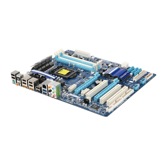
Page 7: Ga-P55A-Ud3P/ Ga-P55A-Ud3R Motherboard Layout
GA-P55A-UD3P/ GA-P55A-UD3R Motherboard Layout GA-P55A-UD3P/ GA-P55A-UD3R Motherboard Layout CPU_FAN CPU_FAN PHASE LED PHASE LED KB_MS_USB KB_MS_USB AT ATX_12V_2 X_12V_2X4 R_SPDIF R_SPDIF LGA1156 LGA1156 USB_ESATA_2 USB_ESATA_2 ATX ATX USB_ESATA_1 USB_ESATA_1 R_USB R_USB PWR_FAN PWR_FAN USB30_LAN USB30_LAN D720200F1 D720200F1 JMicron... -
Page 8: Ga-P55A-Ud3P/Ga-P55A-Ud3R Motherboard Block Diagram
GA-P55A-UD3P/GA-P55A-U GA-P55A-UD3P/GA-P55A-UD3R Motherboard D3R Motherboard Block Diagram Block Diagram PCIe CLK PCIe CLK CPU CLK+/- (133 MHz) CPU CLK+/- (133 MHz) (100 MHz) (100 MHz) DDR3 2200/1333/1066/800 MHz DDR3 2200/1333/1066/800 MHz LGA1156 LGA1156 Dual Channel Memory Dual Channel Memory... -
Page 9: Chapter 1 Hardware Installation
Chapter Chapter Hardware Hardware Installation Installation 1- 1-1 Install Installation ation Precautions Precautions The motherboard contains numerous delicate electronic circuits and components which can The motherboard contains numerous delicate electronic circuits and components which can become damaged as a result of electrostatic discharge (ESD). Prior to installation, carefully read become damaged as a result of electrostatic discharge (ESD). -
Page 10: Product SpeciCations
(XMP) (XMP) memory memory modules modules Go to GIGABYTE's website for the latest supported memory speeds and Go to GIGABYTE's website for the latest supported memory speeds and memory modules) memory modules) Audio Audio Realtek ALC889 codec Realtek ALC889 codec ... - Page 11 USB USB Chipset: Chipset: 2.0/1.1 2.0/1.1 ports ports back back panel, panel, brackets brackets connected to the internal USB connected to the internal USB headers) headers) D720200F1 D720200F1 chip: chip: ...
- Page 12 Only Only GA-P55A- GA-P55A-UD3P UD3P. (Note 1) (Note 1) Due to Windows 32-b Due to Windows 32-bit operating syste it operating system limitation, when more than 4 GB of ph m limitation, when more than 4 GB of...
-
Page 13: Installing The Cpu And Cpu Cooler
Read the following guidelines before you begin to install the CPU: Read the following guidelines before you begin to install the CPU: Make sure that the motherboard supports the CPU. Make sure that the motherboard supports the CPU. • • GIGABYTE's GIGABYTE's website website latest latest support support list.) - Page 14 Follow t Follow the steps he steps below to below to correctly correctly install install the CPU the CPU into the into the motherboard motherboard CPU socke socket. Before installing the CPU, make sure to turn off the computer and unplug the power cord from Before installing the CPU, make sure to turn off the computer and unplug the power cord from the power outlet to prevent damage to the CPU.
-
Page 15: Installing The Cpu Cooler
1-3-2 1-3-2 Installing Installing Cooler Cooler Follow the steps below to correctly install the CPU Follow the steps below to correctly install the CPU cooler on the motherboard. (The following procedure uses cooler on the motherboard. (The following procedure uses ®... -
Page 16: Installing The Memory
Go to GIGABYTE's website for the latest supported memory speeds and memory modu Go to GIGABYTE's website for the latest supported memory speeds and memory modules. -
Page 17: Installing A Memory
1-4-2 1-4-2 Installing Installing Memory Memory Before installing a memory module, make sure to turn off the computer and unplug the power Before installing a memory module, make sure to turn off the computer and unplug the power cord from the power cord from the power outlet to prevent damage to the... -
Page 18: Installing An Expansion Card
Installi Installing Expansion Expansion Card Card Read the following guidelines before you begin to install an expansion card: Read the following guidelines before you begin to install an expansion card: Make sure the mothe Make sure the motherboard supports rboard supports the expansion c... -
Page 19: Back Panel Connectors Connectors
Back Back Panel Panel Connectors Connectors 2.0/1.1 2.0/1.1 Port Port port port supports supports 2.0/1.1 2.0/1.1 specicat specication. ion. this this port port devices devices such such USB k key ey- board/mouse, USB printer, USB ash drive and etc. board/mouse, USB printer, USB ash drive and etc. - Page 20 USB 3.0/2.0 Port USB 3.0/2.0 Port port port supports supports specicat specication compatible compatible 2.0/1.1 2.0/1.1 specicatio specication. Use this port for USB devices such as a USB keyboard/mouse, USB printer, USB ash drive and etc. Use this port for USB devices such as a USB keyboard/mouse, USB printer, USB ash drive and etc.
-
Page 21: Internal Connectors
Internal Internal Connectors Connectors ATX_12V_2X4 ATX_12V_2X4 F_PANEL F_PANEL F_AUDIO F_AUDIO CPU_FAN CPU_FAN CD_IN CD_IN SYS_FAN1/2 SYS_FAN1/2 SPDIF_I SPDIF_I PWR_FAN PWR_FAN SPDIF_O SPDIF_O ... - Page 22 1/2) ATX_12V_2X4/ATX (2x4 12V Power Connector and 2x12 Main Power Connector) 1/2) ATX_12V_2X4/ATX (2x4 12V Power Connector and 2x12 Main Power Connector) With With power connector, power connector, power supply power supply supply supply enough stable enough stable power to power to...
- Page 23 3/4/5) CPU_FAN/SYS_FAN1/SYS_FAN2/PWR_FAN (Fan Headers) 3/4/5) CPU_FAN/SYS_FAN1/SYS_FAN2/PWR_FAN (Fan Headers) motherboard motherboard 4-pin 4-pin header header (CPU_FAN), (CPU_FAN), 4-pin 4-pin (SYS_FAN2) (SYS_FAN2) 3-pin 3-pin (SYS_ (SYS_ FAN1) system fan headers, and a 3-pin power fan header (PWR_FAN). Most fan headers possess a FAN1) system fan headers, and a 3-pin power fan header (PWR_FAN).
- Page 24 (IDE (IDE Connector) Connector) connector supports connector supports devices devices such such hard hard drives drives optical optical drives. drives. Before Before attach- attach- ing the IDE cable, locate the foolproof groove on the connector. If you wish to connect two IDE devices, ing the IDE cable, locate the foolproof groove on the connector.
- Page 25 GSAT GSATA3_6/7 (SA A3_6/7 (SAT 6Gb/s Connectors, 6Gb/s Connectors, Controll Controlled Marvell 9128) Marvell 9128) SATA connectors conform connectors conform SATA 6Gb/s standard 6Gb/s standard compatible with compatible with SATA 3Gb/s and 3Gb/s and SATA 1.5Gb/s standards. Each SATA connector supports a single SATA device. The Marvell 9128 supports 1.5Gb/s standards.
- Page 26 F_PANEL F_PANEL (Front Panel Header) (Front Panel Header) Connect Connect power power switch, switch, reset reset switch, switch, speaker, speaker, chassis chassis intrusion intrusion switch/sensor switch/sensor system system status status indicator on the chassis to this header according to the pin assignments below. Note the positive and indicator on the chassis to this header according to the pin assignments below.
- Page 27 F_AUDIO (Fron F_AUDIO (Front Panel Audio t Panel Audio Header) Header) front front panel panel audio audio header header supports supports Intel Intel High High Denition Denition audio audio (HD) (HD) AC'97 AC'97 audio. audio. connect connect your chassis front panel audio module to this header.
- Page 28 SPDIF_I (S/PDIF SPDIF_I (S/PDIF In Header) In Header) This This header header supports supports digital digital S/PDIF S/PDIF connect connect audio audio device device that that supports supports digital digital audio audio via an optional S/PDIF In cable. For purchasing the optional S/PDIF In cable, please contact the local via an optional S/PDIF In cable.
- Page 29 F_USB1/F_USB2/F_ F_USB1/F_USB2/F_USB3 (USB Head USB3 (USB Headers) ers) headers headers conform conform 2.0/1.1 2.0/1.1 specicat specication. ion. Each Each header header provide provide ports ports optional USB bracket. For purchasing the optional USB bracket. For purchasing the optional USB bracket, please contact the local optional USB bracket, please contact the local dealer...
- Page 30 18) COMA (Serial Port Header) 18) COMA (Serial Port Header) header header provide provide serial serial port port optional optional COM p port cable. cable. purchasing purchasing tional COM port cable, please contact the local dealer. tional COM port cable, please contact the local dealer.
- Page 31 20) PHASE LED 20) PHASE LED number number lighted lighted LEDs LEDs indicates indicates loading. loading. higher higher loading, the loading, the more more number of lighted LEDs. T number of lighted LEDs. To enable the Phase o enable the Phase LED display function, LED display function,...
- Page 32 ...
-
Page 33: Chapter 2 Bios Setup
To see more advanced BIOS Setup menu options, you can press <Ctrl> + <F1> in the main menu of the BIOS Setup program. BIOS Setup program. To upgrade the BIOS, use either the GIGABYTE Q-Flash or @BIOS utility. To upgrade the BIOS, use either the GIGABYTE Q-Flash or @BIOS utility. ... -
Page 34: Startup Screen
Startup Startup Screen Screen The following screens may appear when The following screens may appear when the computer boots. the computer boots. A. The LOGO Screen (Default) A. The LOGO Screen (Default) Function Keys Function Keys B. The POST Screen B. -
Page 35: The Main Menu
<Enter> to accept or items and press <Enter> to accept or enter a sub-menu. enter a sub-menu. (Sample BIOS (Sample BIOS Version: GA-P55A-UD3P F9g) sion: GA-P55A-UD3P F9g) CMOS Setup Utility-Copyright (C) 1984-2010 Award Software CMOS Setup Utility-Copyright (C) 1984-2010 Award Software ... - Page 36 BIOS Setup. (Pressing <Esc> can also carry out this task.) Security Security Chip Chip Conguration Conguration this this menu menu congure congure function. function. Only Only GA-P55A- GA-P55A-UD3P UD3P.
-
Page 37: Mb Intelligent Tw Tweaker(M.i.t Eaker(M.i.t.) .)
Intelli Intelligent gent weaker(M.I. weaker(M.I.T CMOS Setup Utility-Copyright (C) 1984-2010 Award Software CMOS Setup Utility-Copyright (C) 1984-2010 Award Software MB Intelligent Tweaker(M.I.T.) MB Intelligent Tweaker(M.I.T.) Item Help Item Help M.I.T M.I.T Current Current Status Status [Press [Press... - Page 38 Clock Clock Ratio Ratio Allows Allows alter alter clock clock ratio ratio installed installed CPU. CPU. adjustable adjustable range range dependent dependent being installed. being installed. Frequency Frequency Displays Displays current current operating...
- Page 39 (Note) (Note) C3/C6/C7 C3/C6/C7 State State Support Support Allows Allows determine determine whether whether enter enter C3/C6/C7 C3/C6/C7 mode mode system system halt halt state. state. When When abled, the CPU core frequency and voltage will be reduced during system halt state to decrease power abled, the CPU core frequency and voltage will be reduced during system halt state to decrease power consumption.
- Page 40 BCLK BCLK Frequency(Mh Frequency(Mhz) Allows Allows manually manually set t the CP CPU bas base c clock. lock. adjustable adjustable range range is f from 10 100 MHz 0 MHz to 1 1200 MHz. MHz.
- Page 41 Advanced Advanced Memory Memory Settings Settings CMOS Setup Utility-Copyright (C) 1984-2010 Award Software CMOS Setup Utility-Copyright (C) 1984-2010 Award Software Advanced Memory Settings Advanced Memory Settings Item Help Item Help (Note) (Note) Extreme Extreme Memory...
- Page 42 >>>>> >>>>> Channel Channel Timing Timing Settings Settings CMOS Setup Utility-Copyright (C) 1984-2010 Award Software CMOS Setup Utility-Copyright (C) 1984-2010 Award Software Channel A Timing Settings Channel A Timing Settings Item Help Item Help >>>>> Channel >>>>>...
- Page 43 tFAW tFAW Options Options are: are: Auto Auto (default), (default), 1~63. 1~63. Command Command Rate(CMD) Rate(CMD) Options Options are: are: Auto Auto (default), (default), 1~3. 1~3. >>>>> >>>>> Channel Channel A/B Mis Misc T Timing...
- Page 44 >>> MCH/ICH >>> MCH/ICH Core Core default default Auto Auto. default default Auto Auto. >>> DRAM >>> DRAM DRAM DRAM oltage oltage default default Auto Auto. ...
- Page 45 Miscellaneous Settings Miscellaneous Settings CMOS Setup Utility-Copyright (C) 1984-2010 Award Software CMOS Setup Utility-Copyright (C) 1984-2010 Award Software Miscellaneous Settings Miscellaneous Settings Item Help Item Help Isochronous Isochronous Support Support [Enabled] [Enabled] Menu Level Menu Level ...
-
Page 46: Standard Cmos Features
Standard Standard CMOS CMOS Features Features CMOS Setup Utility-Copyright (C) 1984-2010 Award Software CMOS Setup Utility-Copyright (C) 1984-2010 Award Software Standard CMOS Features Standard CMOS Features Item Help Item Help Date Date (mm:dd:yy) (mm:dd:yy) Wed, Wed, Sep 23 2009 Sep 23 2009 Menu Level... - Page 47 IDE C Channel hannel 0, 1 0, 1 Master/Slave Master/Slave Channel Channel Master/Slave Master/Slave Congure Congure your your IDE/SAT IDE/SATA devices devices using using three three methods methods below: below: None None IDE/SAT...
-
Page 48: Advanced Bios Features
Advanced Advanced BIOS BIOS Features Features CMOS Setup Utility-Copyright (C) 1984-2010 Award Software CMOS Setup Utility-Copyright (C) 1984-2010 Award Software Advanced BIOS Features Advanced BIOS Features Item Help Item Help Hard Hard Disk Disk Boot Boot Priority... - Page 49 Screen LOGO LOGO Show Show Allows Allows determine determine whether whether display display GIGABYTE GIGABYTE Logo Logo system system startup. startup. Disabled Disabled displays displays normal POST message. (Default: Enabled) normal POST message. (Default: Enabled) ...
-
Page 50: Integrated Peripherals
item below will be set to RAID(XHD) RAID(XHD) automatically. For automatically. For details on using the GIGABYTE X.H.D utility, refer to Chaper 4, "eXtreme Hard Drive (X.H.D)." details on using the GIGABYTE X.H.D utility, refer to Chaper 4, "eXtreme Hard Drive (X.H.D)." (Default: Disabled) (Default: Disabled) ... - Page 51 AHCI AHCI Congures th Congures the SA SATA controllers t controllers to AHCI o AHCI mode. mode. Advanced Hos Advanced Host Controller In t Controller Interface terface (AHCI) is an interface specication that allows the storage driver to enable advanced (AHCI) is an interface specication that allows the storage driver to enable advanced Serial ATA features such as Native Command Queuing and hot plug.
- Page 52 SMART SMART CMOS Setup Utility-Copyright (C) 1984-2010 Award Software CMOS Setup Utility-Copyright (C) 1984-2010 Award Software SMART LAN SMART LAN Item Help Item Help Start Start detecting detecting Port..Port..Menu Level Menu Level ...
- Page 53 Onboard Onboard Boot Boot Allows Allows decide decide whether whether activate activate boot boot integrated integrated with with onboard onboard chip. chip. (Default: Disabled) (Default: Disabled) Onboard Onboard USB 3.0 C USB 3.0 Controller (NEC ontroller (NEC D720200F1 U...
-
Page 54: Power Management Setup
Power Power Management Management Setup Setup CMOS Setup Utility-Copyright (C) 1984-2010 Award Software CMOS Setup Utility-Copyright (C) 1984-2010 Award Software Power Management Setup Power Management Setup Item Help Item Help ACPI ACPI Suspend Suspend Type Type [S3(STR)] [S3(STR)] Menu Level... - Page 55 Resume by Alarm Resume by Alarm Determines Determines whether whether power power system system desired desired time. time. (Default: (Default: Disabled) Disabled) enabled, enabled, date date time time following: following: Date (of Month) Alarm: Turn on the system at a specic time on each day or on a specic day in a Date (of Month) Alarm: Turn on the system at a specic time on each day or on a specic day in a month.
-
Page 56: Pc Health Status
Health Health Status Status CMOS Setup Utility-Copyright (C) 1984-2010 Award Software CMOS Setup Utility-Copyright (C) 1984-2010 Award Software PC Health Status PC Health Status Item Help Item Help Reset Reset Case Case Open Open Status Status [Disabled] [Disabled] Menu Level... - Page 57 Smart F Smart Mode Mode Species Species control control speed. speed. This This item item congurable congurable only only CPU Smart FAN Control CPU Smart FAN Control is set is set Enabled Enabled. Auto Auto Lets the BIOS a Lets the BIOS automatically d...
-
Page 58: Load Fail-Safe Defaults Defaults
The BIOS defaults settings help the system to operate in optimum state. Always load the Optimized defaults after updating the BIOS or after clearing the after updating the BIOS or after clearing the CMOS values. CMOS values. Only Only GA-P55A- GA-P55A-UD3P UD3P. -
Page 59: Set Supervisor/User Password
To clear the password, press <Enter> on the password item and when requested for the password, press <Enter> again. The message "PASSWORD DISABLED" will appear, indicating the password has been can- <Enter> again. The message "PASSWORD DISABLED" will appear, indicating the password has been can- celled. celled. Only Only GA-P55A- GA-P55A-UD3P UD3P. -
Page 60: Save & Exit Setup
BIOS Setup to the CMOS. Press <N> or <Esc> to return to the BIOS made in BIOS Setup to the CMOS. Press <N> or <Esc> to return to the BIOS Setup Main Menu. Setup Main Menu. Only Only GA-P55A- GA-P55A-UD3P UD3P. -
Page 61: Security Chip ConGuration J
Disabled Disabled Disables Disables security security chip. chip. (Default) (Default) Security Security Chip Chip State State Displays Displays current current settings settings security security chip. chip. Only Only GA-P55A- GA-P55A-UD3P UD3P. - Page 62 ...
-
Page 63: Installing Chipset Drivers
• • new GIGABYTE utilities. Click new GIGABYTE utilities. Click Yes Yes to automatically install the utilities. Or click to automatically install the utilities. Or click No if you want to if you want to... -
Page 64: Application Software
Application Software Software This page displays all the utilities and applications that GIGABYTE develops and some free software. You This page displays all the utilities and applications that GIGABYTE develops and some free software. You can click the can click the Install Install button on the right of an item to install it. -
Page 65: Contact
Contact Contact For the detailed contact information of the GIGABYTE Taiwan headquarter or worldwide branch ofces, click For the detailed contact information of the GIGABYTE Taiwan headquarter or worldwide branch ofces, click the URL on this page to link to the URL on this page to link to the GIGABYTE website. - Page 66 Utilities Utilities This page provides a quick link to GIGABYTE's lately developed utilities for users to install. You can click the This page provides a quick link to GIGABYTE's lately developed utilities for users to install. You can click the Install Install button on the right of an item to install it.
- Page 67 Chapter Chapter Unique Unique Features Features Xpress Xpress Recovery2 Recovery2 Xpress Recovery2 is a utility that allows you to quickly compress and Xpress Recovery2 is a utility that allows you to quickly compress and back up your system data and perform restoration of it. Supporting NTFS, back up your system data and perform restoration of it.
- Page 68 Step 3: Step 3: Step 4: Step 4: When partitioning your hard drive, make sure to When partitioning your hard drive, make sure to After After operati operating system system installe installed, right-c right-click lick leave unallocated space (10 GB or more is recom- leave unallocated space (10 GB or more is recom- Computer ...
- Page 69 D. Using the Restore Function in D. Using the Restore Function in Xpress Recovery2 Xpress Recovery2 Select Select RESTORE RESTORE to restore the backup to your hard drive in to restore the backup to your hard drive in case the system breaks down. The case the system breaks down.
- Page 70 Utilities Utilities ™ ™ ™ ™ GIGABYTE motherboards provide two unique BIOS update tools, Q-Flash GIGABYTE motherboards provide two unique BIOS update tools, Q-Flash and @BIOS and @BIOS . GIGABYTE . GIGABYTE Q-Flash and @BIOS are easy-to-use and allow you to update the BIOS without the need to enter MS-DOS Q-Flash and @BIOS are easy-to-use and allow you to update the BIOS without the need to enter MS-DOS ™...
- Page 71 B. Updating the BIOS B. Updating the BIOS When updating the BIOS, choose the location where the BIOS le is saved. The following procedure as When updating the BIOS, choose the location where the BIOS le is saved. The following procedure as sumes that you save the BIOS le sumes that you save the BIOS le to a oppy disk.
- Page 72 Step 4: Step 4: Press <Esc> and then <Enter> to exit Q-Flash and reboot the system. As the system boots, you should see Press <Esc> and then <Enter> to exit Q-Flash and reboot the system. As the system boots, you should see the new BIOS version is present on the new BIOS version is present on the POST screen.
- Page 73 If the BIOS update le for your motherboard is not present on the @BIOS server site, please manually download the BIOS update le from GIGABYTE's website and follow the manually download the BIOS update le from GIGABYTE's website and follow the...
- Page 74 EasyT EasyTune GIGABYTE's EasyTune 6 is a simple and easy-to-use interface that allows users to ne-tune their system GIGABYTE's EasyTune 6 is a simple and easy-to-use interface that allows users to ne-tune their system settings or do overclock/overvoltage in Windows environment. The user-friendly EasyTune 6 interface also settings or do overclock/overvoltage in Windows environment.
- Page 75 A. Meter Mode ™ ™ In Meter Mode, GIGABYTE Dynamic Energy Saver In Meter Mode, GIGABYTE Dynamic Energy Saver 2 shows how much power they have saved in a set pe- 2 shows how much power they have saved in a set pe- riod of time.
- Page 76 B. Total Mode B. Total Mode In Total Mode, users are able to see how much total power savings they have accumulated in a set period of In Total Mode, users are able to see how much total power savings they have accumulated in a set period of ™...
- Page 77 Start>All Start>All Programs>GIGABYTE> Programs>GIGABYTE>Q-Share. Q-Share. exe to launch the Q-Share tool. Find the exe to launch the Q-Share tool. Find the Q-Share Q-Share icon icon in the notication area and right-click on this icon in the notication area and right-click on this icon...
- Page 78 Smart Smart ™ (Note 1) ™ (Note 1) GIGABYTE Smart 6 GIGABYTE Smart 6 is designed with user-friendliness in mind, and offers a combination of 6 innovative is designed with user-friendliness in mind, and offers a combination of 6 innovative ™...
- Page 79 SMART Recovery SMART Recovery (Note 2) (Note 2) With SMART Recovery, users can quickly create backups of changed data les With SMART Recovery, users can quickly create backups of changed data les or copy or copy les from a specic backup on PATA and SATA hard drives (partitioned on NTFS le system) in les from a specic backup on PATA and SATA hard drives (partitioned on NTFS le system) in Windows Vista.
- Page 80 SMART Recorder SMART Recorder SMART Recorder monitors and records the activities in a system such as the time when the SMART Recorder monitors and records the activities in a system such as the time when the computer was turned on/off or even when large data les were moved within the hard drive or computer was turned on/off or even when large data les were moved within the hard drive or (Note 5) (Note 5)
- Page 81 • • hardware protection. GIGABYTE is not liable for loss of encrypted data as a result of hardware damage. hardware protection. GIGABYTE is not liable for loss of encrypted data as a result of hardware damage. A. Before installing Smart TPM, follow the A.
- Page 82 Auto Auto Green Green Auto Green Auto Green an easy-to-use an easy-to-use tool that tool that provides users provides users with simple with simple options to options to enable system enable system power savings power savings via a Bluetooth cell phone. via a Bluetooth cell phone.
- Page 83 Software screen to individual individually install the ly install the X.H.D utility later. X.H.D utility later. B. Using GIGABYTE eXtreme Hard Drive (X.H.D) B. Using GIGABYTE eXtreme Hard Drive (X.H.D) (Note 2) (Note 2) Instructions: Instructions: Before launching X.H.D, make sure the newly added hard- Before launching X.H.D, make sure the newly added hard-...
- Page 84 ...
- Page 85 Chapter Chapter Appendix Appendix Cong Conguring uring Hard Hard Drive Drive(s) o congure o congure A hard drive(s), A hard drive(s), follow the follow the steps below: steps below: Install SA Install SATA hard drive(s) hard drive(s) your computer.
- Page 86 B. Conguring B. Conguring SATA controller mode in controller mode in BIOS Setup BIOS Setup Make sure to congure the SATA controller mode correctly in system BIOS Setup. Make sure to congure the SATA controller mode correctly in system BIOS Setup. Step 1: Step 1: Turn on your computer and press <Delete>...
- Page 87 C. Conguring a RAID array in RAID BIOS C. Conguring a RAID array in RAID BIOS Enter the RAID BIOS Enter the RAID BIOS setup utility to congure a RAID setup utility to congure a RAID array array. Skip this step and .
- Page 88 Step 3: Step 3: After entering After entering CREATE VOLUME MENU CREATE VOLUME MENU screen, enter a volume name with 1~16 letters (letters cannot screen, enter a volume name with 1~16 letters (letters cannot be special characters) under the be special characters) under the Name Name item and press <Enter>.
- Page 89 Step 5: Step 5: Enter the array capacity and press <Enter>. Finally press <Enter> on the Enter the array capacity and press <Enter>. Finally press <Enter> on the Create Volume Create Volume item to begin creat- item to begin creat- ing the RAID array.
- Page 90 Recovery Volume Options Recovery Volume Options Intel Rapid Recover Technology provides data protection by allowing users to easily restore data and system Intel Rapid Recover Technology provides data protection by allowing users to easily restore data and system operation using a designated recovery drive.
- Page 91 Step 3: Step 3: Press <Enter> under the Press <Enter> under the Select Disks Select Disks item. In the item. In the SELECT DISKS SELECT DISKS box, press <Tab> on the hard drive you box, press <Tab> on the hard drive you want to use for the master drive and press <Space>...
- Page 92 Delete RAID Volume Delete RAID Volume To delete a RAID array, select To delete a RAID array, select Delete RAID Volume Delete RAID Volume MAIN MENU MAIN MENU and press <Enter>. In the and press <Enter>. In the DELETE DELETE VOLUME MENU...
- Page 93 5-1-2 5-1-2 Conguring Conguring JMicron JMicron JMB362 JMB362 Controller Controller A. Installing SATA hard drive(s) in your computer A. Installing SATA hard drive(s) in your computer Attach one Attach one A signal A signal cable to cable to rear rear A hard...
- Page 94 "Press <Ctrl-G> to enter RAID Setup Utility" (Figure 2). Press <Ctrl> + <G> to enter the RAID setup util- ity. ity. GIGABYTE Technology Corp. PCI Express to SATAII HOST Controller ROM v1.07.06 GIGABYTE Technology Corp. PCI Express to SATAII HOST Controller ROM v1.07.06 Copyright...
- Page 95 In the main screen, press <Enter> on the Create RAID Disk Drive Create RAID Disk Drive item. Then the item. Then the Create New RAID Create New RAID screen screen appears (Figure 4). appears (Figure 4). Gigabyte Gigabyte Technology Technology Corp. Corp. RAID RAID Setup Utility Setup Utility v1.07.06 v1.07.06...
- Page 96 item, use the up or down arrow key to select the stripe block size (Figure 6), ranging from 4 KB block size (Figure 6), ranging from 4 KB to 128 KB. Press to 128 KB. Press <Enter>. <Enter>. Gigabyte Gigabyte Technology Technology Corp. Corp. RAID...
- Page 97 When nished, the new RAID array will be displayed in the When nished, the new RAID array will be displayed in the RAID Disk Drive List RAID Disk Drive List block (Figure 8). block (Figure 8). Gigabyte Gigabyte Technology Technology Corp. Corp.
- Page 98 item in the main screen to save your settings before exiting the RAID BIOS utility, then press <Y> (Figure 10). screen to save your settings before exiting the RAID BIOS utility, then press <Y> (Figure 10). Gigabyte Gigabyte Technology Technology Corp.
- Page 99 5-1-3 5-1-3 Congu Conguring ring Marvell Marvell 9128 9128 SATA Contr Controller oller A. Installing SATA hard drive(s) in your computer A. Installing SATA hard drive(s) in your computer Attach one Attach one A signal A signal cable to cable to rear rear...
- Page 100 C. Conguring a RAID array C. Conguring a RAID array Create a RAID Array: Create a RAID Array: Move the selection bar to Move the selection bar to HBA 0: Marvell 0 HBA 0: Marvell 0 and press <Enter>. and press <Enter>.
- Page 101 Select the stripe block size. Options include 32 KB and 64 KB. and 64 KB. Gigabyte Rounding: Gigabyte Rounding: Select whether to permit the installation of a replacement drive that is smaller than Select whether to permit the installation of a replacement drive that is smaller than...
- Page 102 When completed, you can see the new array under When completed, you can see the new array under Topology\Virtual Disks Topology\Virtual Disks (Figure 6). (Figure 6). Marvell BIOS Setup (c) 2009 Marvell Technology Group Ltd. Marvell BIOS Setup (c) 2009 Marvell Technology Group Ltd. Topology Topology Information...
- Page 103 With the Marvell RAID utility, you can set up an array or view the current array status in the operating system. To install the utility, insert the motherboard driver disk, then go to To install the utility, insert the motherboard driver disk, then go to Application Software\Install GIGABYTE Application Software\Install GIGABYTE Utilities Utilities and select...
- Page 104 5-1-4 5-1-4 Making Making RAID/AHCI RAID/AHCI Driver Driver Diskette Diskette (Required (Required AHCI AHCI RAID RAID Mode) Mode) To successfully install operating system onto SATA hard drive(s) that is/are congured to RAID/AHCI mode, To successfully install operating system onto SATA hard drive(s) that is/are congured to RAID/AHCI mode, you need to install the SATA controller driver during the OS installation.
- Page 105 for Windows 32-bit operating system. system. For the JMicron JMB362, select For the JMicron JMB362, select 3) GIGABYTE GSATA driver for 32bit system 3) GIGABYTE GSATA driver for 32bit system for Windows 32-bit op- for Windows 32-bit op- • • erating system.
- Page 106 5-1-5 5-1-5 Installing Installing RAID/AHCI RAID/AHCI Driver Driver Operating Operating System System With the SATA RAID/AHCI driver diskette and correct BIOS settings, you are ready to install Windows Vista/ With the SATA RAID/AHCI driver diskette and correct BIOS settings, you are ready to install Windows Vista/ XP onto your hard XP onto your hard drive(s).
- Page 107 Insert the oppy disk containing the SATA RAID/AHCI driver and press <S>. Then a controller menu similar to Figure 3 below will appear. Select to Figure 3 below will appear. Select RAID/AHCI Driver for GIGABYTE GBB36X Controller RAID/AHCI Driver for GIGABYTE GBB36X Controller ...
- Page 108 B. Installing Windows Vista B. Installing Windows Vista The procedure below assumes that only one RAID array exists in your system. Note: You are not required to The procedure below assumes that only one RAID array exists in your system. Note: You are not required to load the SATA AHCI driver rst when installing Windows Vista onto the RAID drives attached to the Marvell load the SATA AHCI driver rst when installing Windows Vista onto the RAID drives attached to the Marvell 9128 controller.
- Page 109 Step 3: Step 3: When a screen as shown in Figure 7 appears, select When a screen as shown in Figure 7 appears, select Intel(R) ICH8R/ICH9R/ICH10R/DO/5 Series/3400 Se- Intel(R) ICH8R/ICH9R/ICH10R/DO/5 Series/3400 Se- ries SATA RAID Controller ries SATA RAID Controller ...
- Page 110 For the JMicron JMB362: For the JMicron JMB362: Step 1: Step 1: Restart your system to boot from the Windows Vista setup disk and perform standard OS installation steps. Restart your system to boot from the Windows Vista setup disk and perform standard OS installation steps. When a screen similar to that below appears (RAID/AHCI hard drive(s) will not be detected at this stage), When a screen similar to that below appears (RAID/AHCI hard drive(s) will not be detected at this stage), select...
- Page 111 Step 3: Step 3: When a screen as shown in Figure 11 appears, select When a screen as shown in Figure 11 appears, select GIGABYTE GBB36X Controller GIGABYTE GBB36X Controller and click and click Next Next. Figure 11...
- Page 112 C. Rebuilding an Array C. Rebuilding an Array Rebuilding is the process of restoring data to a hard drive from other drives in the array. Rebuilding applies Rebuilding is the process of restoring data to a hard drive from other drives in the array. Rebuilding applies only to fault-tolerant arrays such as RAID 1, RAID 5 or RAID 10 only to fault-tolerant arrays such as RAID 1, RAID 5 or RAID 10 arrays.
- Page 113 Performing the Re Performing the Rebuild in the Ope build in the Operating System rating System • • While in the operating system, make sure the chipset driver has been installed from the motherboard driver While in the operating system, make sure the chipset driver has been installed from the motherboard driver disk.
- Page 114 Restoring the Master Drive to a Prev Restoring the Master Drive to a Previous State (for Recovery V ious State (for Recovery Volume only) olume only) • • When two hard drives are set to Recovery Volume in Update on Request mode, you can restore the master When two hard drives are set to Recovery Volume in Update on Request mode, you can restore the master drive data to the last backup state when needed.
- Page 115 Turn off your computer and replace the failed hard drive with a new one. Use either the RAID setup utility or Turn off your computer and replace the failed hard drive with a new one. Use either the RAID setup utility or the GIGABYTE RAID CONFIGURER utility in the GIGABYTE RAID CONFIGURER utility in the operating system to perform the rebuild.
- Page 116 Next Next. Step 1: Step 1: In the GIGABYTE RAID CONFIGURER screen, In the GIGABYTE RAID CONFIGURER screen, right-click on the array to be rebuilt in the right-click on the array to be rebuilt in the RAID RAID LIST ...
- Page 117 For the Marvell 9128: For the Marvell 9128: Turn off your computer and replace the failed hard drive with a new one. Please note to perform the rebuild, Turn off your computer and replace the failed hard drive with a new one. Please note to perform the rebuild, you must enter the you must enter the GSATA RAID Conguration...
- Page 118 Step 3: Step 3: BGA Rebuild Rebuild item in the item in the Information Information block will display the current rebuild progress. After the rebuild is block will display the current rebuild progress. After the rebuild is complete, the complete, the Status...
- Page 119 Conguring Conguring Audio Audio Input Input Output Output 5-2-1 5-2-1 Conguring Conguring 2/4/5.1/7.1-Channel 2/4/5.1/7.1-Channel Audio Audio The motherboard provides six audio jacks on the back The motherboard provides six audio jacks on the back (Note) (Note) panel which support 2/4/5.1/7.1-channel panel which support 2/4/5.1/7.1-channel audio.
- Page 120 Step 2: Step 2: Connect an audio device to an audio jack. The Connect an audio device to an audio jack. The The cur- The cur- rent connected device is rent connected device is dialog box appears. Select the dialog box appears.
- Page 121 5-2-2 5-2-2 Conguring Conguring S/PDIF S/PDIF In/Out In/Out A. S/PDIF In A. S/PDIF In The S/PDIF In cable (optional) allows you to The S/PDIF In cable (optional) allows you to input digital audio signals to the computer for audio processing. input digital audio signals to the computer for audio processing.
- Page 122 B. S/PDIF Out B. S/PDIF Out The S/PDIF Out jacks can transmit audio signals to an external decoder for decoding to get the best audio The S/PDIF Out jacks can transmit audio signals to an external decoder for decoding to get the best audio quality.
- Page 123 5-2-3 5-2-3 Enabling Enabling Dolby Dolby Home Home Theater Theater Function Function Before Dolby Home Theater is enabled, you get only 2-channel playback output (from the Before Dolby Home Theater is enabled, you get only 2-channel playback output (from the front speakers) when playing 2-channel stereo sources.
- Page 124 5-2-4 5-2-4 Conguring Conguring Microphone Microphone Recording Recording Step 1: Step 1: After installin After installing the audio driver g the audio driver, the , the HD Audio Manager HD Audio Manager icon icon will appear in the will appear in the notication area.
- Page 125 Step 4: Step 4: To raise the recording and playback volume for the To raise the recording and playback volume for the microphone, click the microphone, click the Microphone Boost Microphone Boost icon icon the right of the the right of the Recording Volume Recording...
- Page 126 Step 3: Step 3: When the When the Stereo Mix Stereo Mix item appears, right-click on this item appears, right-click on this item and select item and select Enable Enable. Then set it as the default de- .
- Page 127 Cancel. Then install the onboard HD audio driver from the motherboard . Then install the onboard HD audio driver from the motherboard driver disk or download the audio driver from GIGABYTE's website to install. driver disk or download the audio driver from GIGABYTE's website to install.
- Page 128 5-3-2 5-3-2 Troubl Troubleshooting eshooting Procedure Procedure If you encounter any troubles during system startup, follow the troubleshooting procedure below to solve the If you encounter any troubles during system startup, follow the troubleshooting procedure below to solve the problem.
- Page 129 A A The power supply, CPU or The power supply, CPU or When the computer is turned on, is the CPU cooler running? When the computer is turned on, is the CPU cooler running? CPU socket might fail. CPU socket might fail.
- Page 130 Contravention will be prosecuted. We believe that the information contained herein was accurate in all respects at the time of printing. GIGABYTE believe that the information contained herein was accurate in all respects at the time of printing. GIGABYTE cannot, however, assume any responsibility for errors or omissions in this text.
- Page 131 Finally, we suggest that you practice other environmentally friendly actions by understanding and using the Finally, we suggest that you practice other environmentally friendly actions by understanding and using the energy-sav energy-saving features of ing features of this product (where applicable), recycling the this product (where applicable), recycling the inner and outer inner and outer...
- Page 132 Appendix Appendix - 132 - - 132 -...
- Page 133 ...
- Page 134 Appendix Appendix - 134 - - 134 -...
- Page 135 - China - China • • • • Address: No.6, Bau Chiang Road, Hsin-Tien, Address: No.6, Bau Chiang Road, Hsin-Tien, WEB address : http://www.gigabyte.cn WEB address : http://www.gigabyte.cn Taipei 231, Taiwan Taipei 231, Taiwan Shanghai Shanghai TEL: +886-2-8912-4000 TEL: +886-2-8912-4000...
- Page 136 Republic Republic • • You may go to the GIGABYTE website, select your language You may go to the GIGABYTE website, select your language WEB address : http://www.gigabyte.cz WEB address : http://www.gigabyte.cz in the language list on the top right corner of the website.