
Related Manuals for Gigabyte GA-P55-USB3L


Summary of Contents for Gigabyte GA-P55-USB3L
- Page 1 GA-P55-USB3L LGA1156 socket motherboard for Intel Core i7 processor family/ ® ™ Intel Core i5 processor family/Intel Core i3 processor family ® ™ ® ™ User's Manual Rev. 1001 12ME-P55SB3L-1001R...
-
Page 3: Identifying Your Motherboard Revision
GIGABYTE's prior written permission. Documentation Classifications In order to assist in the use of this product, GIGABYTE provides the following types of documentations: For quick set-up of the product, read the Quick Installation Guide included with the product. -
Page 4: Table Of Contents
Table of Contents Box Contents ........................6 Optional Items .........................6 GA-P55-USB3L Motherboard Layout ................7 GA-P55-USB3L Motherboard Block Diagram..............8 Chapter 1 Hardware Installation ..................9 Installation Precautions ..................9 1-2 Product Specifications ..................10 Installing the CPU and CPU Cooler ............... 13 1-3-1 Installing the CPU ....................13 1-3-2 Installing the CPU Cooler ..................15 Installing the Memory .................. - Page 5 Hard Drive (X.H.D) j ..............78 Chapter 5 Appendix ......................79 5-1 Configuring SATA Hard Drive(s) ..............79 5-1-1 Configuring Intel P55 SATA Controllers ..............79 5-1-2 Configuring GIGABYTE SATA2 SATA Controller ............87 5-1-3 Making a SATA RAID/AHCI Driver Diskette ............93 5-1-4 Installing the SATA RAID/AHCI Driver and Operating System .......94 5-2 Configuring Audio Input and Output .............
-
Page 6: Box Contents
Box Contents GA-P55-USB3L motherboard Motherboard driver disk User's Manual Quick Installation Guide One IDE cable Two SATA 3Gb/s cables I/O Shield • The box contents above are for reference only and the actual items shall depend on the product package you obtain. The box contents are subject to change without notice. -
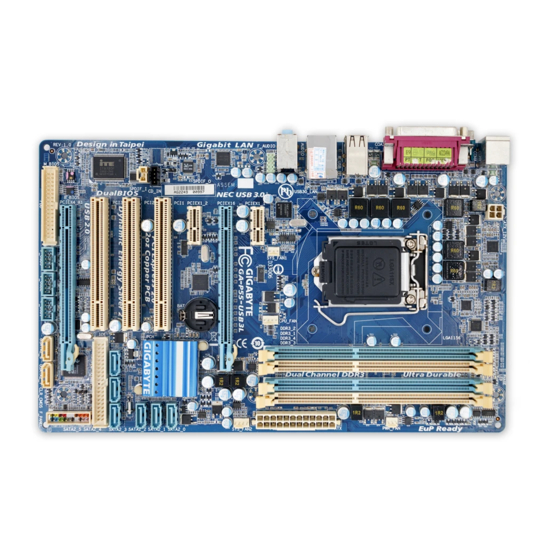
Page 7: Ga-P55-Usb3L Motherboard Layout
CD_IN SATA2_1 PCI2 SPDIF_I SATA2_2 SATA2_5 SATA2_4 SATA2_3 PCI3 CLR_CMOS PCIEX4_X1 GIGABYTE M_BIOS F_PANEL SATA2 F_USB3 j F_USB1 GSATA2_6 GSATA2_7 F_USB2 Only for P55 chipset. (Note) Due to a hardware limitation, the PCIEX1 slot can only accommodate a shorter PCI Express x1 expansion card. -
Page 8: Ga-P55-Usb3L Motherboard Block Diagram
P55/H55 ® PCI Express Bus 6 SATA 3Gb/s PCIe CLK (100 MHz) PCI Express x1 14 USB 2.0/1.1 (Note) (PCIEX1_1) GIGABYTE 2 SATA 3Gb/s SATA2 12 USB 2.0/1.1 ATA-133/100/66/33 IDE Channel (Note) PCI Bus Floppy LPC Bus IT8720 COM Port... -
Page 9: Chapter 1 Hardware Installation
Chapter 1 Hardware Installation Installation Precautions The motherboard contains numerous delicate electronic circuits and components which can become damaged as a result of electrostatic discharge (ESD). Prior to installation, carefully read the user's manual and follow these procedures: • Prior to installation, do not remove or break motherboard S/N (Serial Number) sticker or warranty sticker provided by your dealer. -
Page 10: Product Specifications
™ ® ™ /Intel Core i3 series processor in the LGA1156 package ® ™ (Go to GIGABYTE's website for the latest CPU support list.) L3 cache varies with CPU Chipset Intel P55/H55 Express Chipset ® Memory 4 x 1.5V DDR3 DIMM sockets supporting up to 16 GB of system memory (Note 1) ... - Page 11 Chipset Up to 14 USB 2.0/1.1 ports (8 on the back panel, 6 via the USB (Note 6) brackets connected to the internal USB headers) j Up to 12 USB 2.0/1.1 ports (8 on the back panel, 4 via the USB (Note 6) brackets connected to the internal USB headers) k NEC D720200F1 chip:...
- Page 12 BIOS 2 x 16 Mbit flash Use of licensed AWARD BIOS Support for DualBIOS ™ PnP 1.0a, DMI 2.0, SM BIOS 2.4, ACPI 1.0b Unique Features Support for @BIOS Support for Q-Flash Support for Xpress BIOS Rescue Support for Download Center ...
-
Page 13: Installing The Cpu And Cpu Cooler
Read the following guidelines before you begin to install the CPU: • Make sure that the motherboard supports the CPU. (Go to GIGABYTE's website for the latest CPU support list.) • Always turn off the computer and unplug the power cord from the power outlet before installing the CPU to prevent hardware damage. - Page 14 B. Follow the steps below to correctly install the CPU into the motherboard CPU socket. Before installing the CPU, make sure to turn off the computer and unplug the power cord from the power outlet to prevent damage to the CPU. Step 1: Step 2: Gently press the CPU socket lever handle down...
-
Page 15: Installing The Cpu Cooler
1-3-2 Installing the CPU Cooler Follow the steps below to correctly install the CPU cooler on the motherboard. (The following procedure uses Intel boxed cooler as the example cooler.) ® Male Push Direction of the Arrow Sign on The Top the Male Push of Female Push Pin... -
Page 16: Installing The Memory
• Make sure that the motherboard supports the memory. It is recommended that memory of the same capacity, brand, speed, and chips be used. (Go to GIGABYTE's website for the latest memory support list.) • Always turn off the computer and unplug the power cord from the power outlet before installing the memory to prevent hardware damage. -
Page 17: Installing A Memory
1-4-2 Installing a Memory Before installing a memory module, make sure to turn off the computer and unplug the power cord from the power outlet to prevent damage to the memory module. DDR3 and DDR2 DIMMs are not compatible to each other or DDR DIMMs. Be sure to install DDR3 DIMMs on this motherboard. -
Page 18: Installing An Expansion Card
Installing an Expansion Card Read the following guidelines before you begin to install an expansion card: • Make sure the motherboard supports the expansion card. Carefully read the manual that came with your expansion card. • Always turn off the computer and unplug the power cord from the power outlet before installing an expansion card to prevent hardware damage. -
Page 19: Back Panel Connectors
Back Panel Connectors USB 2.0/1.1 Port The USB port supports the USB 2.0/1.1 specification. Use this port for USB devices such as a USB key- board/mouse, USB printer, USB flash drive and etc. PS/2 Keyboard/Mouse Port Use this port to connect a PS/2 keyboard or mouse. Parallel Port Use the parallel port to connect devices such as a printer, scanner and etc. The parallel port is also called a printer port. - Page 20 Line In Jack (Blue) The default line in jack. Use this audio jack for line in devices such as an optical drive, walkman, etc. Line Out Jack (Green) The default line out jack. Use this audio jack for a headphone or 2-channel speaker. This jack can be used to connect front speakers in a 4/5.1-channel audio configuration.
-
Page 21: Internal Connectors
Internal Connectors ATX_12V F_PANEL CPU_FAN F_AUDIO SYS_FAN1/2 CD_IN PWR_FAN SPDIF_I SPDIF_O F_USB1/F_USB2/(F_USB3 j ) SATA2_0/1/2/3/4/5 CLR_CMOS GSATA2_6/7 PHASE_LED j Only for P55 chipset. Read the following guidelines before connecting external devices: • First make sure your devices are compliant with the connectors you wish to connect. • Before installing the devices, be sure to turn off the devices and your computer. - Page 22 1/2) ATX_12V/ATX (2x2 12V Power Connector and 2x12 Main Power Connector) With the use of the power connector, the power supply can supply enough stable power to all the components on the motherboard. Before connecting the power connector, first make sure the power supply is turned off and all devices are properly installed.
-
Page 23: Fdd (Floppy Disk Drive Connector)
3/4/5) CPU_FAN/SYS_FAN1/SYS_FAN2/PWR_FAN (Fan Headers) The motherboard has a 4-pin CPU fan header (CPU_FAN), a 4-pin (SYS_FAN2) and a 3-pin (SYS_ FAN1) system fan headers, and a 3-pin power fan header (PWR_FAN). Most fan headers possess a foolproof insertion design. When connecting a fan cable, be sure to connect it in the correct orientation (the black connector wire is the ground wire). - Page 24 7) IDE (IDE Connector) The IDE connector supports up to two IDE devices such as hard drives and optical drives. Before attach- ing the IDE cable, locate the foolproof groove on the connector. If you wish to connect two IDE devices, remember to set the jumpers and the cabling according to the role of the IDE devices (for example, master or slave). (For information about configuring master/slave settings for the IDE devices, read the instructions from the device manufacturers.)
-
Page 25: Bat Battery
9) GSATA2_6/7 (SATA 3Gb/s Connectors, Controlled by GIGABYTE SATA2) The SATA connectors conform to SATA 3Gb/s standard and are compatible with SATA 1.5Gb/s standard. Each SATA connector supports a single SATA device. The GIGABYTE SATA2 controller supports RAID 0, RAID 1, and JBOD. Refer to Chapter 5, "Configuring SATA Hard Drive(s)," for instructions on configuring a RAID array. -
Page 26: F_Panel Front Panel Header
11) F_PANEL (Front Panel Header) Connect the power switch, reset switch, speaker, chassis intrusion switch/sensor and system status indicator on the chassis to this header according to the pin assignments below. Note the positive and negative pins before connecting the cables. SPEAK- PWR- Power LED... -
Page 27: Cd In Connector
12) F_AUDIO (Front Panel Audio Header) The front panel audio header supports Intel High Definition audio (HD) and AC'97 audio. You may connect your chassis front panel audio module to this header. Make sure the wire assignments of the module con- nector match the pin assignments of the motherboard header. Incorrect connection between the module connector and the motherboard header will make the device unable to work or even damage it. For HD Front Panel Audio: For AC'97 Front Panel Audio: Pin No. Definition... - Page 28 14) SPDIF_I (S/PDIF In Header) This header supports digital S/PDIF In and can connect to an audio device that supports digital audio out via an optional S/PDIF In cable. For purchasing the optional S/PDIF In cable, please contact the local dealer.
-
Page 29: Clear Cmos Jumper
16) F_USB1/F_USB2/(F_USB3 j ) (USB Headers) The headers conform to USB 2.0/1.1 specification. Each USB header can provide two USB ports via an optional USB bracket. For purchasing the optional USB bracket, please contact the local dealer. Pin No. Definition Power (5V) Power (5V) USB DX- USB DY- USB DX+ USB DY+ No Pin • Do not plug the IEEE 1394 bracket (2x5-pin) cable into the USB header. •... - Page 30 18) PHASE LED The number of lighted LEDs indicates the CPU loading. The higher the CPU loading, the more the number of lighted LEDs. To enable the Phase LED display function, please first enable Dynamic Energy Saver 2. Refer to Chapter 4, "Dynamic Energy Saver 2," for more details. ™ ™ Hardware Installation - 30 -...
-
Page 31: Chapter 2 Bios Setup
To see more advanced BIOS Setup menu options, you can press <Ctrl> + <F1> in the main menu of the BIOS Setup program. To upgrade the BIOS, use either the GIGABYTE Q-Flash or @BIOS utility. Q-Flash allows the user to quickly and easily upgrade or back up BIOS without entering the operating •... -
Page 32: Startup Screen
Startup Screen The following screens may appear when the computer boots. A. The LOGO Screen (Default) Function Keys B. The POST Screen Award Modular BIOS v6.00PG, An Energy Star Ally Copyright (C) 1984-2009, Award Software, Inc. P55-USB3L E12c Motherboard Model BIOS Version Function Keys <DEL>: BIOS Setup <F9>: XpressRecovery2 <F12>: Boot Menu <End>: Qflash... -
Page 33: The Main Menu
The Main Menu Once you enter the BIOS Setup program, the Main Menu (as shown below) appears on the screen. Use ar- row keys to move among the items and press <Enter> to accept or enter a sub-menu. (Sample BIOS Version: E12c) CMOS Setup Utility-Copyright (C) 1984-2009 Award Software MB Intelligent Tweaker(M.I.T.) Load Fail-Safe Defaults... -
Page 34: Advanced Bios Features
The Functions of the <F11> and <F12> keys (For the Main Menu Only) F11: Save CMOS to BIOS This function allows you to save the current BIOS settings to a profile. You can create up to 8 profiles (Profile 1-8) and name each profile. First enter the profile name (to erase the default profile name, use the SPACE key) and then press <Enter> to complete. F12: Load CMOS from BIOS If your system becomes unstable and you have loaded the BIOS default settings, you can use this function to load the BIOS settings from a profile created before, without the hassles of reconfiguring the BIOS settings. First select the profile you wish to load, then press <Enter> to complete. -
Page 35: Mb Intelligent Tweaker(M.i.t.)
MB Intelligent Tweaker(M.I.T.) CMOS Setup Utility-Copyright (C) 1984-2009 Award Software MB Intelligent Tweaker(M.I.T.) Item Help M.I.T Current Status [Press Enter] Menu Level Advanced Frequency Settings [Press Enter] Advanced Memory Settings [Press Enter] Advanced Voltage Settings [Press Enter] ... -
Page 36: Cpu Clock Ratio
CPU Clock Ratio Allows you to alter the clock ratio for the installed CPU. The adjustable range is dependent on the CPU being installed. CPU Frequency Displays the current operating CPU frequency. Advanced CPU Core Features CMOS Setup Utility-Copyright (C) 1984-2009 Award Software Advanced CPU Core Features Item Help Intel(R) Turbo Boost Tech. - Page 37 C3/C6/C7 State Support (Note) Allows you to determine whether to let the CPU enter C3/C6/C7 mode in system halt state. When en- abled, the CPU core frequency and voltage will be reduced during system halt state to decrease power consumption. The C3/C6/C7 state is a more enhanced power-saving state than C1. Auto lets the BIOS automatically configure this setting. (Default: Auto) CPU Thermal Monitor (Note)
- Page 38 BCLK Frequency(Mhz) Allows you to manually set the CPU base clock. The adjustable range is from 100 MHz to 600 MHz. This item is configurable only if the Base Clock(BCLK) Control option is enabled. Important: It is highly recommended that the CPU frequency be set in accordance with the CPU specifi- cations. Extreme Memory Profile (X.M.P.) (Note) Allows the BIOS to read the SPD data on XMP memory module(s) to enhance memory performance when enabled.
- Page 39 Advanced Memory Settings CMOS Setup Utility-Copyright (C) 1984-2009 Award Software Advanced Memory Settings Item Help Extreme Memory Profile (X.M.P.) [Disabled] (Note) Menu Level System Memory Multiplier (SPD) [Auto] Memory Frequency (Mhz) 1333 1333 Performance Enhance [Turbo] DRAM Timing Selectable (SPD) [Auto] Profile DDR Voltage 1.5V Profile QPI Voltage...
-
Page 40: Channel Interleaving
Profile QPI Voltage The value displayed here is dependent on the CPU being used. Channel Interleaving Options are: Auto (default), 1~6. Rank Interleaving Options are: Auto (default), 1~4. >>>>> Channel A/B Timing Settings CMOS Setup Utility-Copyright (C) 1984-2009 Award Software Channel A Timing Settings Item Help >>>>>... - Page 41 tWTP Options are: Auto (default), 1~31. Options are: Auto (default), 1~10 tRFC Options are: Auto (default), 1~255. tRTP Options are: Auto (default), 1~15. tFAW Options are: Auto (default), 1~63. Command Rate(CMD) Options are: Auto (default), 1~3. >>>>> Channel A/B Misc Timing Control B2B CAS Delay Options are: Auto (default), 1~31.
- Page 42 >>>>> Channel A/B Turnaround Settings CMOS Setup Utility-Copyright (C) 1984-2009 Award Software Channel A Turnaround Settings Item Help >>>>> Channel A Reads Followed by Reads Menu Level x Different DIMMs Auto x Different Ranks Auto x On The Same Rank Auto >>>>>...
- Page 43 Advanced Voltage Settings CMOS Setup Utility-Copyright (C) 1984-2009 Award Software Advanced Voltage Settings Item Help ****** Mother Board Voltage Control ****** Menu Level Voltage Types Normal Current ----------------------------------------------------------------------------- >>> CPU Load-Line Calibration [Auto] CPU Vcore 1.20000V [Auto] x Dynamic Vcore(DVID) +0.00000V [Auto] QPI/Vtt Voltage...
- Page 44 Miscellaneous Settings CMOS Setup Utility-Copyright (C) 1984-2009 Award Software Miscellaneous Settings Item Help Isochronous Support [Enabled] Menu Level Virtualization Technology [Enabled] (Note) higf : Move Enter: Select +/-/PU/PD: Value F10: Save ESC: Exit F1: General Help F5: Previous Values F6: Fail-Safe Defaults F7: Optimized Defaults Isochronous Support...
-
Page 45: Standard Cmos Features
Standard CMOS Features CMOS Setup Utility-Copyright (C) 1984-2009 Award Software Standard CMOS Features Item Help Date (mm:dd:yy) Tue, Dec 15 2009 Menu Level Time (hh:mm:ss) 22:31:24 IDE Channel 0 Master [None] IDE Channel 0 Slave [None] IDE Channel 1 Master [None] ... - Page 46 Lets the BIOS automatically detect IDE/SATA devices during the POST. (Default) • Auto Allows you to manually enter the specifications of the hard drive when the hard • Manual drive access mode is set to CHS. Access Mode Sets the hard drive access mode. Options are: Auto (default), CHS, LBA, Large. IDE Channel 2, 3 Master, 4, 5 Master/Slave Extended IDE Drive Configure your IDE/SATA devices by using one of the two methods below: Lets the BIOS automatically detect IDE/SATA devices during the POST.
-
Page 47: Advanced Bios Features
Advanced BIOS Features CMOS Setup Utility-Copyright (C) 1984-2009 Award Software Advanced BIOS Features Item Help Hard Disk Boot Priority [Press Enter] Menu Level Quick Boot [Disabled] First Boot Device [Hard Disk] Second Boot Device [CDROM] Third Boot Device [Floppy] Password Check [Setup]... -
Page 48: Init Display First
Allows you to set a delay time for the BIOS to initialize the hard drive as the system boots up. The ad- justable range is from 0 to 15 seconds. (Default: 0) Full Screen LOGO Show Allows you to determine whether to display the GIGABYTE Logo at system startup. Disabled displays normal POST message. (Default: Enabled) Backup BIOS Image to HDD Allows the system to copy the BIOS image file to the hard drive. If the system BIOS is corrupted, it will... -
Page 49: Integrated Peripherals
Enables or disables the X.H.D function for the SATA controllers integrated in the Intel P55 Chipset. When set to Enabled, the PCH SATA Control Mode item below will be set to RAID(XHD) automatically. For details on using the GIGABYTE X.H.D utility, refer to Chaper 4, "eXtreme Hard Drive (X.H.D)." (Default: Disabled) -
Page 50: Usb Storage Function
USB Storage Function Determines whether to detect USB storage devices, including USB flash drives and USB hard drives during the POST. (Default: Enabled) Turbo USB3.0 (NEC USB 3.0 Controller) (Note) Determines whether to set the PCIe speed of the NEC USB 3.0 controller to PCIe Gen 2. Please note that when only one graphics card is installed on the PCIEX16 slot, it will operate at up to x8 mode if ei- ther one of the two controllers is set to PCIe Gen 2. -
Page 51: Onboard Parallel Port
Enables or disables the NEC USB 3.0 controller. (Default: Enabled) Onboard SATA/IDE Device (GIGABYTE SATA2, IDE and GSATA2_6/7 Connectors) Enables or disables the IDE and SATA controllers integrated in the GIGABYTE SATA2 chip. (Default: Enabled) Onboard SATA/IDE Ctrl Mode (GIGABYTE SATA2, IDE and GSATA2_6/7 Connectors) Enables or disables RAID for the SATA controller integrated in the GIGABYTE SATA2 chip or configures the SATA controller to AHCI mode. -
Page 52: Power Management Setup
Power Management Setup CMOS Setup Utility-Copyright (C) 1984-2009 Award Software Power Management Setup Item Help ACPI Suspend Type [S3(STR)] Menu Level Soft-Off by PWR-BTTN [Instant-Off] PME Event Wake Up [Enabled] Power On by Ring [Enabled] Resume by Alarm [Disabled] Date (of Month) Alarm Everyday Time (hh:mm:ss) Alarm... -
Page 53: Eup Support
Resume by Alarm Determines whether to power on the system at a desired time. (Default: Disabled) If enabled, set the date and time as following: Date (of Month) Alarm: Turn on the system at a specific time on each day or on a specific day in a month. Time (hh: mm: ss) Alarm: Set the time at which the system will be powered on automatically. Note: When using this function, avoid inadequate shutdown from the operating system or removal of the AC power, or the settings may not be effective. -
Page 54: Pc Health Status
PC Health Status CMOS Setup Utility-Copyright (C) 1984-2009 Award Software PC Health Status Item Help Reset Case Open Status [Disabled] Menu Level Case Opened Vcore 1.220V DDR15V 1.504V 4.972V +12V 12.048V Current System Temperature Current CPU Temperature Current CPU FAN Speed 3375 RPM Current SYSTEM FAN2 Speed 0 RPM... - Page 55 CPU Smart FAN Mode Specifies how to control CPU fan speed. This item is configurable only if CPU Smart FAN Control is set to Enabled. Auto Lets the BIOS automatically detect the type of CPU fan installed and sets the optimal CPU fan control mode. (Default) Voltage Sets Voltage mode for a 3-pin CPU fan. Sets PWM mode for a 4-pin CPU fan.
-
Page 56: Load Fail-Safe Defaults
Load Fail-Safe Defaults CMOS Setup Utility-Copyright (C) 1984-2009 Award Software MB Intelligent Tweaker(M.I.T.) Load Fail-Safe Defaults Standard CMOS Features Load Optimized Defaults Advanced BIOS Features Set Supervisor Password Integrated Peripherals Set User Password Power Management Setup Save &... -
Page 57: Set Supervisor/User Password
2-11 Set Supervisor/User Password CMOS Setup Utility-Copyright (C) 1984-2009 Award Software MB Intelligent Tweaker(M.I.T.) Load Fail-Safe Defaults Standard CMOS Features Load Optimized Defaults Advanced BIOS Features Set Supervisor Password Integrated Peripherals Set User Password Power Management Setup Save &... -
Page 58: Save & Exit Setup
2-12 Save & Exit Setup CMOS Setup Utility-Copyright (C) 1984-2009 Award Software MB Intelligent Tweaker(M.I.T.) Load Fail-Safe Defaults Standard CMOS Features Load Optimized Defaults Save to CMOS and EXIT (Y/N)? Y Advanced BIOS Features Set Supervisor Password Integrated Peripherals Set User Password ... -
Page 59: Chapter 3 Drivers Installation
Chapter 3 Drivers Installation • Before installing the drivers, first install the operating system. • After installing the operating system, insert the motherboard driver disk into your optical drive. The driver Autorun screen is automatically displayed which looks like that shown in the screen shot below. (If the driver Autorun screen does not appear automatically, go to My Computer, double-click the optical drive and execute the Run.exe program.) Installing Chipset Drivers After inserting the driver disk, "Xpress Install"... -
Page 60: Application Software
Application Software This page displays all the utilities and applications that GIGABYTE develops and some free software. You can click the Install button on the right of an item to install it. Technical Manuals This page provides GIGABYTE's application guides, content descriptions for this driver disk, and the mother- board manuals. -
Page 61: Contact
Contact For the detailed contact information of the GIGABYTE Taiwan headquarter or worldwide branch offices, click the URL on this page to link to the GIGABYTE website. System This page provides the basic system information. - 61 - Drivers Installation... -
Page 62: Download Center
The latest version of the BIOS, drivers, or applications will be displayed. New Utilities This page provides a quick link to GIGABYTE's lately developed utilities for users to install. You can click the Install button on the right of an item to install it. -
Page 63: Chapter 4 Unique Features
Chapter 4 Unique Features Xpress Recovery2 Xpress Recovery2 is a utility that allows you to quickly compress and back up your system data and perform restoration of it. Supporting NTFS, FAT32, and FAT16 file systems, Xpress Recovery2 can back up data on PATA and SATA hard drives and restore it. - Page 64 Step 3: Step 4: When partitioning your hard drive, make sure to After the operating system is installed, right-click the Computer icon on your desktop and select leave unallocated space (10 GB or more is recom- mended; actual size requirements vary, depending Manage.
- Page 65 D. Using the Restore Function in Xpress Recovery2 Select RESTORE to restore the backup to your hard drive in case the system breaks down. The RESTORE option will not be present if no backup is created before. E. Removing the Backup Step 1: Step 2: If you wish to remove the backup file, select...
-
Page 66: Bios Update Utilities
BIOS Update Utilities GIGABYTE motherboards provide two unique BIOS update tools, Q-Flash and @BIOS . GIGABYTE ™ ™ Q-Flash and @BIOS are easy-to-use and allow you to update the BIOS without the need to enter MS-DOS mode. Additionally, this motherboard features the DualBIOS design, which enhances protection for the ™... - Page 67 B. Updating the BIOS When updating the BIOS, choose the location where the BIOS file is saved. The following procedure as- sumes that you save the BIOS file to a floppy disk. Step 1: 1. Insert the floppy disk containing the BIOS file into the floppy disk drive. In the main menu of Q-Flash, use the up or down arrow key to select Update BIOS from Drive and press <Enter>. •...
- Page 68 Step 4: Press <Esc> and then <Enter> to exit Q-Flash and reboot the system. As the system boots, you should see the new BIOS version is present on the POST screen. Step 5: During the POST, press <Delete> to enter BIOS Setup. Select Load Optimized Defaults and press <Enter> to load BIOS defaults.
-
Page 69: Updating The Bios With The @Bios Utility
BIOS or a system that is unable to start. Do not use the G.O.M. (GIGABYTE Online Management) function when using @BIOS. GIGABYTE product warranty does not cover any BIOS damage or system failure resulting from an inad- equate BIOS flashing. -
Page 70: Easytune 6
EasyTune 6 GIGABYTE's EasyTune 6 is a simple and easy-to-use interface that allows users to fine-tune their system settings or do overclock/overvoltage in Windows environment. The user-friendly EasyTune 6 interface also includes tabbed pages for CPU and memory information, letting users read their system-related information without the need to install additional software. The EasyTune 6 Interface... -
Page 71: Dynamic Energy Saver ™ 2
The Dynamic Energy Saver 2 Interface ™ A. Meter Mode In Meter Mode, GIGABYTE Dynamic Energy Saver 2 shows how much power they have saved in a set pe- ™ riod of time. 12 13 14 Meter Mode - Button Information Table... - Page 72 B. Total Mode In Total Mode, users are able to see how much total power savings they have accumulated in a set period of time since activating Dynamic Energy Saver 2 for the first time ™ (Note 3) 11 12 13 Total Mode - Button Information Table Button Description Dynamic Energy Saver On/Off Switch (Default: Off) Current CPU Power Consumption...
-
Page 73: Q-Share
Q-Share, you are able to share your data with computers on the same network, making full use of Internet resources. Directions for using Q-Share After installing Q-Share from the motherboard driver disk, go to Start>All Programs>GIGABYTE>Q-Share. exe to launch the Q-Share tool. Find the Q-Share icon in the notification area and right-click on this icon to configure the data sharing settings. -
Page 74: Smart 6
Smart 6 ™ GIGABYTE Smart 6 is designed with user-friendliness in mind, and offers a combination of 6 innovative ™ (Note 1) software utilities that provide easier and smarter PC system management. Smart 6 allows you to speed up ™... -
Page 75: Smart Recovery
SMART Recovery With SMART Recovery, users can quickly create backups of changed data files or copy (Note 2) files from a specific backup on PATA and SATA hard drives (partitioned on NTFS file system) in Windows Vista. Instructions: In the main menu, click the Config button to open the Smart Recov- ery Preference dialog box. The Smart Recovery Preference dialog box: Button Function Enable... -
Page 76: Smart Timelock
SMART Recorder SMART Recorder monitors and records the activities in a system such as the time when the computer was turned on/off or even when large data files were moved within the hard drive or copied to an external storage device (Note 5) Instructions: Select the Enable check box at the bottom of the ON/OFF Recorder or File Monitor tab to enable the recording of system on/off time or files copying. Entering the Smart 6 password is required before you... -
Page 77: Auto Green
Auto Green Auto Green is an easy-to-use tool that provides users with simple options to enable system power savings via a Bluetooth cell phone. When the phone is out of the range of the computer's Bluetooth receiver, the sys- tem will enter the specified power saving mode. The Configuration dialog box: First, you have to set your Bluetooth cell phone as a portable key. -
Page 78: Extreme Hard Drive (X.h.d) J
After installing the operating system, insert the motherboard driver disk. You can click the Xpress Install All button to automatically install all motherboard drivers, including the X.H.D utility. Or you can go to the Applica- tion Software screen to individually install the X.H.D utility later. B. Using GIGABYTE eXtreme Hard Drive (X.H.D) (Note 2) Instructions: Before launching X.H.D, make sure the newly added hard-... -
Page 79: Chapter 5 Appendix
Chapter 5 Appendix Configuring SATA Hard Drive(s) To configure SATA hard drive(s), follow the steps below: A. Install SATA hard drive(s) in your computer. B. Configure SATA controller mode in BIOS Setup. C. Configure a RAID array in RAID BIOS. (Note 1) D. Make a floppy disk containing the SATA RAID/AHCI driver for Windows XP. (Note 2) E. Install the SATA RAID/AHCI driver and operating system. (Note 2) Before you begin Please prepare:... - Page 80 B. Configuring SATA controller mode in BIOS Setup Make sure to configure the SATA controller mode correctly in system BIOS Setup. Step 1: Turn on your computer and press <Delete> to enter BIOS Setup during the POST (Power-On Self-Test). To create RAID, set PCH SATA Control Mode under the Integrated Peripherals menu to RAID(XHD) (Figure 1) (IDE by default).
- Page 81 C. Configuring a RAID array in RAID BIOS Enter the RAID BIOS setup utility to configure a RAID array. Skip this step and proceed with the installation of Windows operating system for a non-RAID configuration. Step 1: After the POST memory test begins and before the operating system boot begins, look for a message which says "Press <Ctrl-I> to enter Configuration Utility" (Figure 2). Press <Ctrl> + <I> to enter the P55 RAID Con- figuration Utility. Intel(R) Rapid Storage Technology - option ROM - 9.5.0.1037 Copyright(C) 2003-09 Intel Corporation.
- Page 82 Step 3: After entering the CREATE VOLUME MENU screen, enter a volume name with 1~16 letters (letters cannot be special characters) under the Name item and press <Enter>. Then, select a RAID level (Figure 4). RAID levels supported include RAID 0, RAID 1, Recovery, RAID 10, and RAID 5 (the selections available depend on the number of the hard drives being installed).
- Page 83 Step 5: Enter the array capacity and press <Enter>. Finally press <Enter> on the Create Volume item to begin creat- ing the RAID array. When prompted to confirm whether to create this volume, press <Y> to confirm or <N> to cancel (Figure 6). Intel(R) Rapid Storage Technology - option ROM - 9.5.0.1037 Copyright(C) 2003-09 Intel Corporation. All Rights Reserved. [ CREATE VOLUME MENU ] Name : Volume0 RAID Level : RAID0(Stripe)
- Page 84 Recovery Volume Options Intel Rapid Recover Technology provides data protection by allowing users to easily restore data and system operation using a designated recovery drive. With the Rapid Recovery Technology, which employs RAID 1 functionality, users can copy the data from the master drive to the recovery drive; if needed, the data on the recovery drive can be restored back to the master drive.
- Page 85 Step 3: Press <Enter> under the Select Disks item. In the SELECT DISKS box, press <Tab> on the hard drive you want to use for the master drive and press <Space> on the hard drive you want to use for the recovery drive. (Make sure the recovery drive has equal or larger capacity than the master drive.) Then press <Enter>...
- Page 86 Delete RAID Volume To delete a RAID array, select Delete RAID Volume in MAIN MENU and press <Enter>. In the DELETE VOLUME MENU section, use the up or down arrow key to select the array to be deleted and press <Delete>. When prompted to confirm your selection (Figure 12), press <Y> to confirm or <N> to abort.
-
Page 87: Configuring Gigabyte Sata2 Sata Controller
Attach one end of the SATA signal cable to the rear of the SATA hard drive and the other end to available SATA port on the motherboard. On this motherboard, the GSATA2_6 and GSATA2_7 ports are supported by the GIGABYTE SATA2 SATA controller. Then connect the power connector from your power supply to the hard drive. - Page 88 After the POST memory test begins and before the operating system boot begins, look for a message which says "Press <Ctrl-G> to enter RAID Setup Utility" (Figure 2). Press <Ctrl> + <G> to enter the RAID setup util- ity. GIGABYTE Technology Corp. PCI Express to SATAII HOST Controller ROM v1.07.06 Copyright (C) 2005-2009 Gigabyte Technology Corp. (http://www.gigabyte.com)
- Page 89 In the main screen, press <Enter> on the Create RAID Disk Drive item. Then the Create New RAID screen appears (Figure 4). Gigabyte Technology Corp. RAID Setup Utility v1.07.06 [ Create New RAID ] [ Hard Disk Drive List ]...
- Page 90 4. Set Block Size (RAID 0 only): Under the Block item, use the up or down arrow key to select the stripe block size (Figure 6), ranging from 4 KB to 128 KB. Press <Enter>. Gigabyte Technology Corp. RAID Setup Utility v1.07.06 [ Create New RAID ]...
- Page 91 When finished, the new RAID array will be displayed in the RAID Disk Drive List block (Figure 8). Gigabyte Technology Corp. RAID Setup Utility v1.07.06 [ Main Menu ] [ Hard Disk Drive List ] Create RAID Disk Drive Model Name Capacity Type/Status Delete RAID Disk Drive HDD0: ST3120026AS 120 GB...
- Page 92 7. Save and Exit Setup: After configuring the RAID array, select the Save And Exit Setup item in the main screen to save your settings before exiting the RAID BIOS utility, then press <Y> (Figure 10). Gigabyte Technology Corp. RAID Setup Utility v1.07.06 [ Main Menu ] [ Hard Disk Drive List ]...
-
Page 93: Making A Sata Raid/Ahci Driver Diskette
Figure 4, • For the Intel P55, select 7) Intel Rapid Storage driver for 32bit system for Windows XP operating sys- tem. • For the GIGABYTE SATA2, select 3) GIGABYTE GSATA driver for 32bit system for Windows 32-bit operating system. Your system will then automatically copy the driver files to the floppy disk. Press any key to exit when finished. -
Page 94: Installing The Sata Raid/Ahci Driver And Operating System
5-1-4 Installing the SATA RAID/AHCI Driver and Operating System With the SATA RAID/AHCI driver diskette and correct BIOS settings, you are ready to install Windows Vista/ XP onto your hard drive(s). The followings are examples of Windows XP and Vista installation. A. - Page 95 For the GIGABYTE SATA2: Insert the floppy disk containing the SATA RAID/AHCI driver and press <S>. Then a controller menu similar to Figure 3 below will appear. Select RAID/AHCI Driver for GIGABYTE GBB36X Controller (x32) and press <Enter>. Windows Setup You have chosen to configure a SCSI Adapter for use with Windows, using a device support disk provided by an adapter manufacturer. Select the SCSI Adapter you want from the following list, or press ESC to return to the previous screen.
- Page 96 B. Installing Windows Vista (The procedure below assumes that only one RAID array exists in your system.) For the Intel P55: Step 1: Restart your system to boot from the Windows Vista setup disk and perform standard OS installation steps. When a screen similar to that below appears (RAID hard drive will not be detected at this stage), select Load Driver (Figure 4).
- Page 97 Step 3: When a screen as shown in Figure 6 appears, select Intel(R) ICH8R/ICH9R/ICH10R/DO/5 Series/3400 Se- ries SATA RAID Controller and click Next. Figure 6 Step 4: After the driver is loaded, select the RAID/AHCI drive(s) where you want to install the operating system and then click Next to continue the OS installation (Figure 7).
- Page 98 For the GIGABYTE SATA2: Step 1: Restart your system to boot from the Windows Vista setup disk and perform standard OS installation steps. When a screen similar to that below appears (RAID/AHCI hard drive(s) will not be detected at this stage), select Load Driver (Figure 8).
- Page 99 Step 3: When a screen as shown in Figure 10 appears, select GIGABYTE GBB36X Controller and click Next. Figure 10 Step 4: After the driver is loaded, select the RAID/AHCI drive(s) where you want to install the operating system and then click Next to continue the OS installation (Figure 11).
- Page 100 C. Rebuilding an Array Rebuilding is the process of restoring data to a hard drive from other drives in the array. Rebuilding applies only to fault-tolerant arrays such as RAID 1, RAID 5 or RAID 10 arrays. The procedures below assume a new drive is added to replace a failed drive to rebuild a RAID 1 array.
- Page 101 • Performing the Rebuild in the Operating System While in the operating system, make sure the chipset driver has been installed from the motherboard driver disk. Then launch the Intel Rapid Stroage Technology utility from All Programs in the Start menu. Step 2: Select a new drive to rebuild the RAID and click Rebuild.
- Page 102 • Restoring the Master Drive to a Previous State (for Recovery Volume only) When two hard drives are set to Recovery Volume in Update on Request mode, you can restore the master drive data to the last backup state when needed. For example, in case the master drive detects a virus, you can restore the recovery drive data to the master drive.
- Page 103 Turn off your computer and replace the failed hard drive with a new one. Use either the RAID setup utility or the GIGABYTE RAID CONFIGURER utility in the operating system to perform the rebuild. • Rebuilding with the RAID setup utility Step 1: When the message "Press <Ctrl-G>...
- Page 104 • Rebuilding in the operating system Make sure the GIGABYTE SATA2 SATA controller driver has been installed from the motherboard driver disk. Launch the GIGABYTE RAID CONFIGURER from All Programs in the Start menu. Step 2: When the Rebuilding RAID Wizard appears, click Next.
-
Page 105: Configuring Audio Input And Output
Configuring Audio Input and Output 5-2-1 Configuring 2/4/5.1/7.1-Channel Audio The motherboard provides three audio jacks on the back panel which support 2/4/5.1/7.1 -channel audio. The picture to the (Note) right shows the default audio jack assignments. Line In The integrated HD (High Definition) audio provides jack retask- Front Speaker Out ing capability that allows the user to change the function for each jack through the audio driver. - Page 106 The pictures to the right show the 7.1-channel speak- 7.1-Channel Speakers: er configurations. Front Speaker Out Rear Speaker Out Center/Subwoofer Speaker Out Side Speaker Out Step 2: Connect an audio device to an audio jack. The The cur- rent connected device is dialog box appears. Select the device according to the type of device you connect.
- Page 107 C. Activating an AC'97 Front Panel Audio Module If your chassis provides an AC'97 front panel audio mod- ule, to activate the AC'97 functionality, click the tool icon on the Speaker Configuration tab. On the Connector Settings dialog box, select the Disable front panel jack detection check box.
-
Page 108: Configuring S/Pdif In/Out
5-2-2 Configuring S/PDIF In/Out A. S/PDIF In The S/PDIF In cable (optional) allows you to input digital audio signals to the computer for audio processing. S/PDIF In Cable Optical Coaxial S/PDIF In S/PDIF In 1. Installing the S/PDIF In Cable: Step 1: Step 2: First, attach the connector at the end of the cable... - Page 109 B. S/PDIF Out The S/PDIF Out jacks can transmit audio signals to an external decoder for decoding to get the best audio quality. 1. Connecting a S/PDIF Out Cable: S/PDIF Coaxial Cable Connect a S/PDIF coaxial cable to an external decoder for transmitting the S/PDIF digital audio signals. 2.
-
Page 110: Configuring Microphone Recording
5-2-3 Configuring Microphone Recording Step 1: After installing the audio driver, the HD Audio Manager icon will appear in the notification area. Double-click the icon to access the HD Audio Manager. Step 2: Connect your microphone to the Mic in jack (pink) on the back panel or the Mic in jack (pink) on the front panel. Then configure the jack for microphone function- ality. - Page 111 Step 4: To raise the recording and playback volume for the microphone, click the Microphone Boost icon the right of the Recording Volume slider and set the Microphone Boost level. Step 5: After completing the settings above, click Start, point to All Programs, point to Accessories, and then click Sound Recorder to begin the sound recording.
-
Page 112: Using The Sound Recorder
Step 3: When the Stereo Mix item appears, right-click on this item and select Enable. Then set it as the default de- vice. Step 4: Now you can access the HD Audio Manager to config- ure Stereo Mix and use Sound Recorder to record the sound. -
Page 113: Troubleshooting
New Hardware Wizard appears, click Cancel. Then install the onboard HD audio driver from the motherboard driver disk or download the audio driver from GIGABYTE's website to install. For more details, go to the Support&Downloads\Motherboards\FAQ page on our website and search for "onboard HD audio driver."... -
Page 114: Troubleshooting Procedure
5-3-2 Troubleshooting Procedure If you encounter any troubles during system startup, follow the troubleshooting procedure below to solve the problem. START Turn off the power. Remove all peripherals, connecting cables, and power cord etc. Make sure the motherboard does not short-circuit with the chassis or Isolate the short circuit. - Page 115 The power supply, CPU or When the computer is turned on, is the CPU cooler running? CPU socket might fail. The problem is verified and solved. The graphics card, expansion slot, or monitor Check if there is display on your monitor. might fail. The problem is verified and solved. Turn off the computer. Plug in the keyboard and mouse and restart the computer.
-
Page 116: Regulatory Statements
Contravention will be prosecuted. We believe that the information contained herein was accurate in all respects at the time of printing. GIGABYTE cannot, however, assume any responsibility for errors or omissions in this text. Also note that the informa- tion in this document is subject to change without notice and should not be construed as a commitment by GIGABYTE. - Page 117 Finally, we suggest that you practice other environmentally friendly actions by understanding and using the energy-saving features of this product (where applicable), recycling the inner and outer packaging (including shipping containers) this product was delivered in, and by disposing of or recycling used batteries properly. With your help, we can reduce the amount of natural resources needed to produce electrical and electronic equipment, minimize the use of landfills for the disposal of "end of life" products, and generally improve our quality of life by ensuring that potentially hazardous substances are not released into the environment and...
- Page 118 Appendix - 118 -...
- Page 119 Shenyang http://rma.gigabyte.us Web address: http://latam.giga-byte.com TEL: +86-24-83992901 • Giga-Byte SINGAPORE PTE. LTD. - Singapore FAX: +86-24-83992909 • GIGABYTE TECHNOLOGY (INDIA) LIMITED - India WEB address : http://www.gigabyte.sg • Thailand WEB address : http://www.gigabyte.in WEB address : http://th.giga-byte.com • Saudi Arabia •...
- Page 120 WEB address : http://www.gigabyte.com.gr WEB address : http://www.gigabyte.kz • Czech Republic You may go to the GIGABYTE website, select your language WEB address : http://www.gigabyte.cz in the language list on the top right corner of the website. • GIGABYTE Global Service System...