Advertisement
Quick Links
2
5a
5b
1
8a
9c
8b
9b
10
11
21
23
22
24
30
25
26
PLEASE LEAVE this M&I Sheet with the owner, maintenance plumber, etc. as
items relating to ongoing maintenance suggestions and procedures are included.
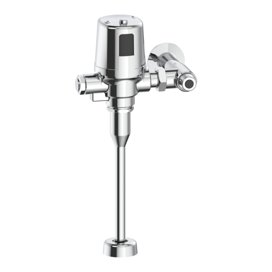
Record model number:
3
Valve Type
0 = W/C (Water Closet)
2 = W/C - 22" outlet tube
3 = Urinal
4
17
27
7a
7b
6a
6b
8c
16
9a
12
13
15
14
28
15
28
Filter Screen
29
31
Electronic Exposed
TECK
81T2__ 1__ __A - __ __ - __ __
Power Option
BT = Battery
Additional Options
HW = Hardwired
(leave blank if not applicable)
30 = w/Sloan
20 = Less Stop Assy
1 = V/B Tube w/Tee Assy (W/C only)
18
19
20
For valves manufactured after January 2013.
II Flush Valves
®
(with H2Optics
Alternate Flush Volumes
(leave blank if not applicable)
6 = 6 L (litre) (1.6 gal) fixed flush (W/C only)
13 = 13 L (3.4 gal) flush (W/C Retrofit Kits only)
48 = 4.8 L (1.27 gal) fixed flush (W/C only)
19 = 1.9 L (0.5 gal) fixed flush (Urinal only)
05 = 0.5 L (0.125 gal) fixed flush (Urinal only)
/Zurn
Tail
®
®
Slip Joint Nut Installation
)
®
212385 Rev. A
Advertisement

Related Manuals for Delta TECK II 81T201BT


Summary of Contents for Delta TECK II 81T201BT
- Page 1 Electronic Exposed TECK II Flush Valves ® (with H2Optics ® Record model number: 81T2__ 1__ __A - __ __ - __ __ Valve Type Alternate Flush Volumes 0 = W/C (Water Closet) (leave blank if not applicable) 2 = W/C - 22” outlet tube 6 = 6 L (litre) (1.6 gal) fixed flush (W/C only) 3 = Urinal 13 = 13 L (3.4 gal) flush (W/C Retrofit Kits only)
- Page 2 NOTE: Refer to TECK fl ushometer repair parts and maintenance manual for additional parts and information. ٭Package quantities may change. Check the parts section of the latest Delta Commercial Faucet Price List for current quantities. ٭٭For valves manufactured before January 2013, you must replace both 061323A / 061324A diaphragm assembly and 062007A brass seat with O-ring.
- Page 3 Table 1 - Cap/Pin/Diaphragm Confi guration Table Cap/Solenoid & Regulating Screw Assembly Flush Volume Poppet Pin Diaphragm Assembly (includes Cap, Solenoid, Regulating Screw) 061341A 060508A 5.0٭٭L (0.125 gal) ٭UR - Fixed 061342A 061324A 9.1٭٭L (0.5 gal) 060507A 061346A UR - Adjustable 1.9L (0.5 gal) 061344A 8.4٭٭L (1.27 gal)
- Page 4 Product # Max. ±11mm ( ”) Min. All 81T201BT/ 292mm 121mm 54mm 81T201HW variations* (11½”) (4¾”) (2.13”) All 81T231BT/ 330mm 121mm 54mm 81T231HW variations* (13”) (4¾”) (2.13”) * Note: -30 models, B = 114mm - 131 mm (4.5” to 5.18”) Flushometer MUST be paired with a fixture of equivalent flush volume.
- Page 5 INSTALLATION INSTRUCTIONS - BATTERY FLUSHOMETER (for Hardwire, skip to Step 3) STEP 1 - • Install battery flushometer to fixture. • Open inlet stop. STEP 2 - • Follow instructions on yellow static label (Figure 4). Note: The batteries are already installed and the product is in hibernation mode waiting to be activated. •...
-
Page 6: Enter Setup Mode
ENTER SETUP MODE EXIT SETUP MODE ALL LIGHTS WILL BE ON, HOLD DOWN THE ELECTRONIC OVERRIDE BUTTON (AGAIN) TO ENTER SETUP MODE - HOLD DOWN TO EXIT SETUP AND RETURN TO UNTIL ONLY THE SOLID BLUE LIGHT IS ON, ELECTRONIC OVERRIDE BUTTON UNTIL OPERATION MODE - HOLD DOWN RELEASE TO RETURN TO OPERATE MODE. -
Page 7: To Replace Batteries
BATTERY STRENGTH INDICATOR & BATTERY REPLACEMENT TO CHECK BATTERY STRENGTH: During Operation Mode - press and hold down the electronic override button for approximately 10 seconds. DO NOT RELEASE BUTTON WHEN SOLID BLUE LIGHT IS PRESENT - KEEP HOLDING DOWN. After 10 seconds, the battery strength will be displayed via the red lights. - Page 8 NOTE: DO NOT USE EXCESSIVE FORCE to close the inlet stop stem. We RECOMMEND that the flushometer be flushed while closing the inlet stop. The noise created by the water flow or the flow into the fixture will stop when the inlet water is shut off. NOTE: Always use DELTA COMMERCIAL GENUINE PARTS to maintain the warranty. EXCESSIVE NOISE: PARTIALLY close the inlet stop.
- Page 9 Fig. 11 Detail “A” Detail “B” INADVERTENT FLUSHING (see Figure 11) Check for the presence of a mirror or reflective surface across from the flushometer. Cover the reflective surface by standing in front or with paper, if this resolves the inadvertent flushing then: Follow the instructions “Making Adjustments to the Electronic Features”...
- Page 10 ® All parts of Delta® HDF® and TECK® faucets are warranted to the original commercial purchaser to be free from defects in material, fi nish and workmanship for a period of fi ve (5) years unless otherwise specifi cally stated in the catalogue and price book. This warranty is made to the original commercial purchaser and shall be eff ective from date of purchase as shown on the purchaser’s receipt.