Advertisement
Quick Links
RECORD MODEL NUMBER:
81T2 __ 1SP-__-MMO
VALVE TYPE
ALTERNATE FLUSH VOLUMES
0
Water Closet
Blank
3
Urinal
42
48
19
TYPE DE
05
SOUPAPE
DF
0
Toilettes
3
Urinoir
AUTRES VOLUMES DE CHASSE
Vide
42
48
19
05
DF
PLEASE LEAVE the Maintenance & Installation (M&I) manual with owner for maintenance and troubleshooting information.
VEUILLEZ LAISSER cette feuille d'instruction de fabrication avec le propriétaire, le plombier d'entretien, etc. puisque les suggestions et procédures d'entretien
Adjustable flush (W/C and Urinal)
4.2 Lpf (1.1 gpf) fixed flush (W/C only)
4.8 Lpf (1.27 gpf) fixed flush (W/C only)
1.9 Lpf (0.5 gpf) fixed flush (Urinal only)
0.5 Lpf (0.125 gpf) fixed flush (Urinal only)
Dual Flush Option
Chasse d'eau réglable (toilette et urinoir)
chasse fixe de 4,2 Lpf (1,1 gpf) (seulement pour les toilettes)
chasse fixe de 4,8 Lpf (1,27 gpf) (seulement pour les toilettes)
chasse fixe de 1,9 Lpf (0,5 gpf) (seulement pour l'urinoir)
chasse fixe de 0,50 Lpf (0,13 gpf) (seulement pour l'urinoir)
Option de chasse double
Water Closet /
Toilette
des articles y sont incluses
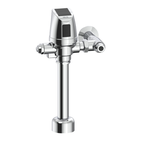
Electronic Exposed Teck
Flush Valves
(Solar Power Option)
Robinet de Chasse Électronique
TECK
(Option d'alimentation solaire)
Urinal /
Urinoir
213104 Rev. A
II à Découvert
MD
II
®
Advertisement

Related Manuals for Delta Electronic Exposed Teck II


Summary of Contents for Delta Electronic Exposed Teck II
- Page 1 Electronic Exposed Teck ® Flush Valves (Solar Power Option) Robinet de Chasse Électronique RECORD MODEL NUMBER: TECK II à Découvert 81T2 __ 1SP-__-MMO (Option d’alimentation solaire) VALVE TYPE ALTERNATE FLUSH VOLUMES Water Closet Blank Adjustable flush (W/C and Urinal) Urinal 4.2 Lpf (1.1 gpf) fixed flush (W/C only) 4.8 Lpf (1.27 gpf) fixed flush (W/C only) 1.9 Lpf (0.5 gpf) fixed flush (Urinal only)
- Page 2 Installation Specifications / Spécifications d’installation Flushometer MUST be paired with a fixture of equivalent flush Fig. 1 volume. RECOMMENDED WATER SUPPLY: Water Closet Minimum flowing pressure: 25 psi (172 kPa), Minimum flow rate: 25 gpm (95 L/min) Urinal Minimum flowing pressure: 25 psi (172 kPa), Minimum flow rate: 8 gpm (30 L/min) DIMENSIONAL TABLE (see Figure 1)
- Page 3 Installation Notes/ Notes d’installation (see Figure 2) • To prevent valve malfunction, do not install a handrail or any other objects within the detection range of the sensor. (see Figure 2-A) DO NOT install the Flushometer facing a mirror or other highly reflective surface (example - stainless steel, polished metal). (see Figure 2-B) •...
-
Page 4: Installation
Installation/ Installation It is important to FLUSH and thoroughly CLEAN water lines to ELIMINATE • Fig. 3 contaminants (example - scale, sediment, gravel, cuttings, solder, etc.). • Where the water has a high sediment content, a FILTER SCREEN in the supply line should help protect working parts of flushometers. - Page 5 STEP 2 - FLUSHOMETER INSTALLATION: Fig. 4 (see Figure 4) 1. Assemble Vacuum Breaker components (B, C, D) into the Outlet Tube (E). 2. Assemble the outlet tube with vacuum breaker onto the Flushometer Body (A) and tighten Coupling Ring (F) into the flushometer body. 3.
- Page 6 IF LEFT HAND STOP IS REQUIRED (see Figure 6) Fig. 6 1. Remove Hex Screw (B) on the side of the Cover (A). 2. Carefully rotate and lift Cover (A) off the Flushometer Body (D) watching not to damage the Solenoid Wires (C). ...
- Page 7 Flush Volume Adjustment / Réglage Du Volume De Chasse Adjustable Models (listed below) (see Figure 8) Fixed Non-Adjustable Models (listed below) The Flushometer CANNOT be adjusted according to job conditions and The Regulating Screw (G) may be adjusted according to job conditions and fixture installed to the proper water volume to flush that particular fixture.
- Page 8 Function Adjustments / Réglages de la fonction Fig. 9 Optional: Only required if factory settings are not preferred. STEP 1 - CAP REMOVAL (see Figure 9) 1. Remove Hex Screw (B) on the side of the Cover (A). 2. Carefully rotate and lift Cover (A) off the Flushometer Body (D) without damage to the Solenoid Wires (C).
- Page 9 STEP 3 - MODE MODIFICATION (see Figure 10) 1. Once in operation mode, if adjustments are preferred, the installer must access Set-up Mode by pressing the Blue Button (B) on the back of the Sensor (A) for 5 seconds and release it when a solid blue light is visible. ...
- Page 10 STEP 4 - SENSOR ADJUSTMENT VERIFICATION: For Water Closets: (see Figure 11) Fig. 11 1. Configure the sensing ranges based on the appropriate bowl length (aa) for the installation. 2. Verify the correct distance is selected by: i. Exiting Set-up Mode and re-installing the cover assembly onto flushometer body. ii.
- Page 11 Avoid directing water spray or cleaners directly at sensor lens. Cette soupape de vidange commerciale de Delta est conçue et fabriquée conformément aux plus strictes normes de qualité et de rendement. Avec des soins appropriés, elle vous donnera des années de service sans problème.
- Page 12 BATTERY STRENGTH INDICATOR & BATTERY REPLACEMENT / INDICATEUR DE CHARGE DE LA PILE ET REMPLACEMENT DE LA PILE BATTERY STRENGTH INDICATION (see Figure 14) Fig. 14 During normal operation - the battery level is displayed after every use. The colour of the LED light displayed will indicate the battery level.
- Page 13 Repair Parts/ Pièces de Rechange Page - 13 of 19 213104 Rev. A...
- Page 14 * Package quantities may change. Check the parts section of the latest Delta Commercial Faucet Price List for current quantities. * Les quantités dans les paquets peuvent varier. Vérifiez la section des pièces du plus récent catalogue de prix des produits commerciaux de Delta pour les quantités exactes.
- Page 15 Table 1 - Cap/Pin/Diaphragm Configuration Table Tableau 1 – Table de Configuration du Capuchon/Tige/Diaphragme Urinal/Urinoir Water Closet/ Toilette Adjustable/ Ajustable & Adjustable/ *Fixed/ *Non Réglable *Fixed/ *Non Réglable Dual Flush/ Chasse Ajustable d’eau double **0.5 Lpf **1.9 Lpf 1.9 Lpf **4.2 Lpf **4.8 Lpf 6.0 Lpf...
- Page 16 PROBLEM SOLVING & MAINTENANCE SUGGESTIONS We recommend that you use only genuine Delta ® replacement parts to maintain the warranty. DO NOT USE EXCESSIVE FORCE to close the inlet stop stem. We RECOMMEND that the flushometer be flushed while closing the inlet stop. The noise created by the water flow or the flow into the fixture will stop when the inlet water is shut off.
- Page 17 RÉSOLUTION DE PROBLÈMES ET SUGGESTION D’ENTRETIEN Nous vous recommandons également d’utiliser seulement des pièces de rechange Delta pour conserver la garantie. N’UTILISEZ PAS UNE FORCE EXCESSIVE pour fermer la tige d’arrêt d’entrée. Nous vous RECOMMANDONS que la soupape de chasse d’eau soit rincée lorsque vous fermez l’arrêt d’entrée.
- Page 18 Changes or modifications not expressly approved by the manufacturer could void the user’s authority to operate the equipment. CAN ICES-3 (A) / NMB-3(A) 2018 Masco Canada Ltd. © For further technical assistance, call Delta Commercial Technical Service at 1-800-387-8277 (Canada) or 1-877-509-2680 (U.S.A.). Page - 18 of 19 213104 Rev. A...
- Page 19 à ses propres frais. Tous changements ou modi cations non explicitement approuvés par Delta risquent d’annuler le droit de l’utilisateur à utiliser l’équipement. CAN ICES-3 (A) / NMB-3(A) © 2018 Masco Canada Lte.