Extron electronics FOX3 Matrix Series User Manual
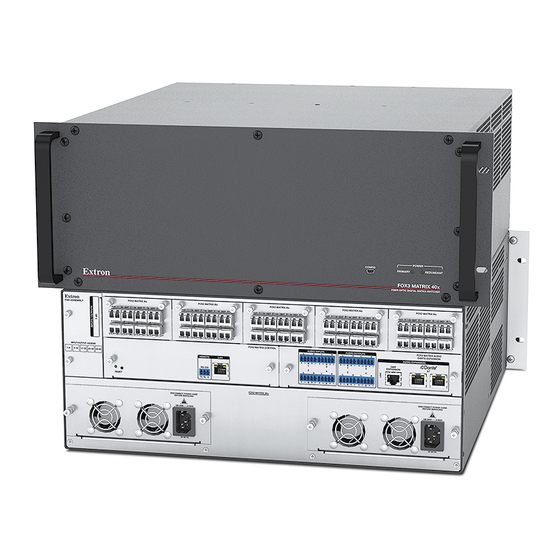
Configurable fiber optic digital matrix switcher
Hide thumbs
Also See for FOX3 Matrix Series:
- User manual (81 pages) ,
- Setup manual (17 pages) ,
- Installation manual (4 pages)

Related Manuals for Extron electronics FOX3 Matrix Series


Summary of Contents for Extron electronics FOX3 Matrix Series
- Page 1 User Guide Fiber Optic Matrix Switchers FOX3 Matrix Series Configurable Fiber Optic Digital Matrix Switcher 68-2987-01 Rev. B 06 20...
- Page 2 Safety Instructions Safety Instructions • English Istruzioni di sicurezza • Italiano AVVERTENZA: Il simbolo, , se usato sul prodotto, serve ad WARNING This symbol, , when used on the product, is intended avvertire l’utente della presenza di tensione non isolata pericolosa to alert the user of the presence of uninsulated dangerous voltage all’interno del contenitore del prodotto che può...
- Page 3 Copyright www.extron.com © 2020 Extron Electronics. All rights reserved. Trademarks All trademarks mentioned in this guide are the properties of their respective owners. The following registered trademarks ( ® ), registered service marks ( ), and trademarks ( ) are the property of RGB Systems, Inc. or Extron Electronics (see the current list of trademarks on the...
- Page 4 Débarrassez-vous des piles usagées selon le mode d’emploi. Class 1 Laser Product Any service to this product must be carried out by Extron Electronics and its qualified service personnel. CAUTION: Using controls, making adjustments, or performing procedures in a manner other than what is specified herein may result in hazardous radiation exposure.
- Page 5 Conventions Used in this Guide Notifications The following notifications are used: WARNING: Potential risk of severe injury or death. AVERTISSEMENT : Risque potentiel de blessure grave ou de mort. CAUTION: Risk of minor personal injury. ATTENTION : Risque de blessure mineure. ATTENTION: •...
-
Page 7: Table Of Contents
Performing Soft System Resets Web Page Panels ..........41 (Resets 3, 4, and 5) ........17 Device Info Panel ........... 42 Performing a Hard Reset (Reset 1) ....17 Device Status Panel ........43 Troubleshooting ..........17 FOX3 Matrix Series Switchers • Contents... - Page 8 Battery and Power Precautions ......48 FOX3 Matrix Replacement Cards ....... 48 Removing and Installing an I/O Module ....49 Removing and Installing a Power Supply Module ........51 Removing and Installing a Fan Assembly ... 52 FOX3 Matrix Series Switchers • Contents viii...
-
Page 9: Introduction
The matrix switcher can route multiple input/output configurations simultaneously. The switcher is configurable, assembled from individual input/output (I/O) boards, each of which supports 8 inputs and 8 outputs. The FOX3 Matrix Switchers are compatible with the FOX3 endpoints. FOX3 Matrix Series Switchers • Introduction... - Page 10 The matrix switchers are housed in rack-mountable, high metal enclosures with mounting flanges for a standard 19-inch rack. The switchers have two IEC power input connectors to provide 100 VAC to 240 VAC, 50-60 Hz power to the unit. FOX3 Matrix Series Switchers • Introduction...
-
Page 11: Fiber Optic I/O Boards
The switcher can be operated remotely by any of the following connected to the switcher: • A control system A PC computer • NOTE: The controller board is hot-swappable. You do not need to power down the switcher to remove or install a controller board. FOX3 Matrix Series Switchers • Introduction... -
Page 12: Fiber Cable Transmission Modes
DMP expansion port, and analog audio inputs ® and outputs — The FOX3 Matrix features unique audio capabilities with leading-edge audio matrix switching between any input and any output in the FOX3 systems. FOX3 Matrix Series Switchers • Introduction... - Page 13 Ethernet monitoring and control — The matrix switcher can be proactively monitored and managed over a LAN, WAN, or the Internet, using standard TCP/IP protocols. Ethernet control provides for remote selection of input and output ties, system set-up and configuration, and advanced system diagnostics. FOX3 Matrix Series Switchers • Introduction...
- Page 14 Internal Extron Everlast power supply — Provides worldwide power compatibility, with high-demonstrated reliability and low power consumption for reduced operating cost. • Extron Everlast Power Supply is covered by a 7-year parts and labor warranty. FOX3 Matrix Series Switchers • Introduction...
-
Page 15: Installation
Install the Product Configuration Software (PCS) (see Software/Firmware Installation on page 30). … (Optional) Upload a System Map (see the FOX3 Matrix Series PCS Help File). Perform Physical Installation … If desired, install the switcher in a rack (see Mounting the Switcher on page 47 ). -
Page 16: Rear Panel Boards, Cabling, And Features
Fiber optic boards with connectors and LEDs Power connectors Replaceable fan assembly Audio Inputs LAN Ethernet port Audio Outputs Remote RS-232 port DMP Expansion port and LED Reset button and LED Dante AT Expansion ports Power supplies FOX3 Matrix Series Switchers • Installation... -
Page 17: I/O Boards
In connector on a FOX transmitter. Output LED — See Fiber optic I/O board LED indications on page 10. INPUTS Receiving Unit OUT* Optional for return data FOX3 Matrix Series Switchers • Installation... -
Page 18: Cooling Fan Assembly
100 Mbps (100Base-T — Fast Ethernet) — Requires CAT 5e UTP or STP cable at • minimum. • 1000 Mbps (1000Base-T — IEEE 802.3ab) half-duplex and full-duplex Ethernet — Requires CAT 5, CAT 5e, CAT 6, or CAT 7 UTP or STP cable. FOX3 Matrix Series Switchers • Installation... -
Page 19: Remote Port
NOTE: The factory configured passwords for all accounts on this device have been set to the device serial number. In the event of a complete system reset, the passwords convert to the default, which is extron for the Admin and User. FOX3 Matrix Series Switchers • Installation... -
Page 20: Power Supply Modules
Extron FOX3 transmitters and receivers and other Dante-compatible audio devices. Download and install the latest version of Dante Controller for Windows from the Dante Software/Firmware Installation Controller product page (see on page 30). FOX3 Matrix Series Switchers • Installation... -
Page 21: Operation
Removing and Installing a Power Supply Module failed (see on page 51 to replace the power supply). Unlit — Indicates that the power supply is not installed in the frame or is not fully • seated in the bay. FOX3 Matrix Series Switchers • Operation... -
Page 22: Power
In System Map mode, multiple SFP modules can be combined via PCS to create a configuration map. This mode is used to simplify system switching and USB group switching for cross display applications (see the FOX3 Matrix Series PCS Help File for detailed instructions). -
Page 23: Reset Operations
Analysez minutieusement les différents modes de réinitialisation. Appliquer le mauvais mode de réinitialisation peut causer une perte inattendue de la programmation de la mémoire flash, une reconfiguration des ports ou une réinitialisation du processeur. FOX3 Matrix Series Switchers • Operation... - Page 24 In the event of a complete system reset, the passwords convert to the default, which is extron for the Admin and User (see Roles and Permissions Panel on page 45 to change a password). FOX3 Matrix Series Switchers • Operation...
-
Page 25: Performing Soft System Resets (Resets 3, 4, And 5)
Check the cabling and make corrections as necessary. Call the Extron S3 Sales and Technical Support Hotline if necessary (see the contact numbers on the last page of this guide for the nearest Extron office). FOX3 Matrix Series Switchers • Operation... -
Page 26: Sis Configuration And Control
SIS commands via an SSH client and IP address 203.0.113.22 and port 22023 (see Establishing a Connection on page 19 to connect to an SSH client). FOX3 Matrix Series Switchers • SIS Configuration and Control... -
Page 27: Ethernet (Lan) Port
Administrators have full access to all switching capabilities and editing functions. Users can create ties, create and recall presets, set mutes, and view all settings with the exception of passwords. FOX3 Matrix Series Switchers • SIS Configuration and Control... -
Page 28: Using Verbose Mode
The switcher does not expect a response from the host, but, for example, the host program might request a new status. (C) COPYRIGHT 2020, Extron Electronics, FOX3 Matrix xxx, Vx.xx, 60-nnnn-01 {day,date,time} The switcher issues the copyright message when it is first powered on or when a connection via Internet protocol (IP) is established. -
Page 29: Switcher Error Responses
Device not present — Maximum number of connections exceeded — Bad filename or file not found NOTE: If the unit does not support or recognize the entered commands, no response is issued. FOX3 Matrix Series Switchers • SIS Configuration and Control... -
Page 30: Using The Command And Response Tables
Unless stated otherwise, SIS commands are not case sensitive. Special Characters The switcher accepts all alpha-numeric characters permitted except , and “space”, as the name of the switcher, passwords, or locally created file names. FOX3 Matrix Series Switchers • SIS Configuration and Control... -
Page 31: System Definitions
(approximately 1 dB per step 0% to 100% [default]) number of outputs (Analog 50001-50004) SFP modules installed — 0 = No SFP 1 = MM SFP 2 = SM SFP 3 = Unknown SFP FOX3 Matrix Series Switchers • SIS Configuration and Control... -
Page 32: Command And Response Table For Sis Commands
• All KEY: = Input number – Maximum number of inputs for your configuration ( = untie) = Output number – Maximum number of outputs for your configuration ( = untie) FOX3 Matrix Series Switchers • SIS Configuration and Control... - Page 33 = Return audio source number – Maximum number of outputs (from a Rx unit, Expansion 40001 40032 50001 50004 Dante , Analog = Analog audio destination number (to Tx) – Maximum number of inputs FOX3 Matrix Series Switchers • SIS Configuration and Control...
- Page 34 50004 Analog View mute View output mutes 50001 50004 Verbose mode 2/3 50001 50004 The last four numbers are 50001-50004 local analog audio output. KEY: = Mute = Unmuted, = Muted FOX3 Matrix Series Switchers • SIS Configuration and Control...
- Page 35 SIS over SSH (port 22023) Enable Echo Returns command entered with 1ECHO Echo1 response. Disable Echo Returns response only. 0ECHO Echo0 View Echo status ECHO KEY: = Enable or disable = Disable, = Enable (default) FOX3 Matrix Series Switchers • SIS Configuration and Control...
- Page 36 = Power Supply failed/Installed = Maximum virtual video matrix size InputxOutput (example: 80x80) 30001 30008 40001 40032 = Audio input number – Maximum number of inputs or Expansion , Dante 50001 50004 Analog FOX3 Matrix Series Switchers • SIS Configuration and Control...
-
Page 37: Product Configuration Software
In the event of a complete system reset, the passwords convert to the default, which is extron for the Admin and User (see Roles and Permissions Panel on page 45 to change a password). FOX3 Matrix Series Switcher • Product Configuration Software... -
Page 38: Software/Firmware Installation
Scroll down to the alphabetic navigation bar (see figure 12). Figure 12. Software Installation Click the appropriate letter to locate the software or firmware. Click Download and follow the on-screen instructions (see figure 13, for PCS). Figure 13. PCS Software Download FOX3 Matrix Series Switcher • Product Configuration Software... - Page 39 Double-click the executable file and follow the on-screen directions to install the software. For Firmware: To install via PCS, see Update Firmware in the Device Menu on page 38. To install via the internal web pages, see the Firmware Panel on page 44. FOX3 Matrix Series Switcher • Product Configuration Software...
-
Page 40: Connecting To Pcs
Click in the field to edit (see figure 16) . Click Apply to complete and close. Alternatively, click Apply and Connect to complete and connect to the device. Click Cancel to close the box without changes. Figure 16. Communication Settings Box FOX3 Matrix Series Switcher • Product Configuration Software... -
Page 41: Tcp/Ip Panel
), enter port 4523. NOTE: If the Telnet port number is not known, leave this field blank. PCS will scan for the port. Click the Connect button ( ). A new device tab opens. FOX3 Matrix Series Switcher • Product Configuration Software... -
Page 42: Offline Device Preview
The New Configuration File dialog box opens (see figure 19). Select the desired device model from the Device Models list (see figure 19). Click the Configure button. A new offline device configuration tab opens. Figure 19. New Configuration File Dialog Box FOX3 Matrix Series Switcher • Product Configuration Software... -
Page 43: Software Overview
PCS Software Menu Show Expanded Device Tabs Selecting Show Expanded Device Tabs from the Software menu displays the device IP address or connection method in the Device Figure 22. Expanded Device Tab tab. FOX3 Matrix Series Switcher • Product Configuration Software... - Page 44 From the Software menu, select Tutorial. The Tutorial dialog box opens. Click the I Get It! button to close the dialog box. Extron PCS Help Open the PCS help file for general PCS operations. From the Software menu, select Extron PCS Help. FOX3 Matrix Series Switcher • Product Configuration Software...
- Page 45 Click the Close Session(s) and Exit button ( ) to disconnect the software from connected devices, close all offline device tabs, and close the software. Alternatively, click the Cancel button ( ) to leave the software open. FOX3 Matrix Series Switcher • Product Configuration Software...
- Page 46 Restore to Multiple Devices — Upload a saved configuration file for a FOX3 Matrix to multiple devices on the network. NOTE: The connected devices must be connected via LAN. • FOX3 Matrix Help — Open the FOX3 Matrix Series PCS Help File in a separate window. FOX3 Matrix Series Switcher • Product Configuration Software...
- Page 47 NOTE: The connected devices must be connected via LAN. About This Module — Open the About This Module dialog box, with the module part • number and firmware version of the connected device. FOX3 Matrix Series Switcher • Product Configuration Software...
-
Page 48: Internal Web Pages
In the event of a complete system reset, the passwords convert to the default, which is extron for the Admin and User (see Roles and Permissions Panel on page 45 to change a password). FOX3 Matrix Series Switcher • Internal Web Page... -
Page 49: Disabling Compatibility Mode
Dante Device Info Panel The panels that can be edited have an EDIT link to click to access the panel. To view general information about the FOX3 Matrix, click the ABOUT link ( About the FOX3 Matrix). FOX3 Matrix Series Switcher • Internal Web Page... -
Page 50: Device Info Panel
When finished editing, click SAVE to confirm your changes or CANCEL to close the window without making changes. Clicking the X in the upper-right corner of the screen also closes the window. FOX3 Matrix Series Switcher • Internal Web Page... -
Page 51: Device Status Panel
FOX3, and turn DHCP On and Off. To set the IP addresses: ) in the Network Settings panel. The Network Click EDIT (see figure 31 [left], Settings panel opens to allow edits (right). Figure 31. Network Settings Panel FOX3 Matrix Series Switcher • Internal Web Page... -
Page 52: Firmware Panel
When the update is completed, the message window closes and the message Firmware Upload Complete appears near the top of the screen. The new firmware filename appears beside Version in the Firmware panel. FOX3 Matrix Series Switcher • Internal Web Page... -
Page 53: Roles And Permissions Panel
CANCEL or the X in the upper-right corner. Passwords can be changed but they cannot be removed entirely. The FOX3 must have passwords at all times. These fields cannot be blank. Figure 35. Passwords Dialog Box FOX3 Matrix Series Switcher • Internal Web Page... -
Page 54: Dante Device Info Panel
FOX3 Matrix, such as the firmware version, copyright, part number, licenses, patents and web page version. Click on the View the End User License Agreement link to view the user license. Figure 37. About Panel FOX3 Matrix Series Switcher • Internal Web Page... -
Page 55: Maintenance And Modifications
Reliable earthing (grounding) — Reliable earthing of rack-mounted equipment should be maintained. Particular attention should be given to supply connections other than direct connections to the branch circuit (such as the use of power strips). FOX3 Matrix Series Switcher • Maintenance and Modifications... -
Page 56: Mounting Instructions
FOX3 160x FOX3 320x 8 port fiber I/O card MM 8 port fiber I/O card SM Power supply Fan assembly Controller card Audio card * indicates the frames that share the same part FOX3 Matrix Series Switcher • Maintenance and Modifications... -
Page 57: Removing And Installing An I/O Module
Thumbscrews should be tightened with a tool after both initial installation and subsequent access to the panel. • Les vis doivent être serrées avec un outil adapté après la première installation et l’accès postérieur au panneau. FOX3 Matrix Series Switcher • Maintenance and Modifications... - Page 58 Gently seat the replacement module into the backplane. Use a screwdriver to tighten the left and right captive panel screws to lock the replacement module in place. FOX3 Matrix Series Switcher • Maintenance and Modifications...
-
Page 59: Removing And Installing A Power Supply Module
Gently slide the replacement power supply into the enclosure until the module meets resistance. Gently seat the replacement power supply in the backplane. Use a screwdriver to tighten the left and right captive panel screws to secure the replacement power supply in place. FOX3 Matrix Series Switcher • Maintenance and Modifications... -
Page 60: Removing And Installing A Fan Assembly
Gently slide the replacement fan assemby into the enclosure until the fan meets resistance. Gently seat the replacement fan assemby into the backplane. Use a screwdriver to tighten the top and bottom captive panel screws to secure the replacement fan assemby in place. FOX3 Matrix Series Switcher • Maintenance and Modifications... - Page 61 Extron Electronics makes no further warranties either expressed or implied with respect to the product and its quality, performance, merchantability, or fitness for any particular use. In no event will Extron Electronics be liable for direct, indirect, or consequential damages resulting from any defect in this product even if Extron Electronics has been advised of such damage.