Extron electronics FOX3 Matrix 80x User Manual
Configurable fiber optic digital matrix switcher
Hide thumbs
Also See for FOX3 Matrix 80x:
- Setup manual (13 pages) ,
- User manual (61 pages) ,
- User manual (81 pages)

Related Manuals for Extron electronics FOX3 Matrix 80x


Summary of Contents for Extron electronics FOX3 Matrix 80x
- Page 1 User Guide Fiber Optic Matrix Switchers FOX3 Matrix 80x Configurable Fiber Optic Digital Matrix Switcher 68-2987-01 Rev. A 04 20...
- Page 2 Safety Instructions Safety Instructions • English Istruzioni di sicurezza • Italiano AVVERTENZA: Il simbolo, , se usato sul prodotto, serve ad WARNING This symbol, , when used on the product, is intended avvertire l’utente della presenza di tensione non isolata pericolosa to alert the user of the presence of uninsulated dangerous voltage all’interno del contenitore del prodotto che può...
- Page 3 Copyright www.extron.com © 2020 Extron Electronics. All rights reserved. Trademarks All trademarks mentioned in this guide are the properties of their respective owners. The following registered trademarks ( ® ), registered service marks ( ), and trademarks ( ) are the property of RGB Systems, Inc. or Extron Electronics (see the current list of trademarks on the...
- Page 4 Débarrassez-vous des piles usagées selon le mode d’emploi. Class 1 Laser Product Any service to this product must be carried out by Extron Electronics and its qualified service personnel. CAUTION: Using controls, making adjustments, or performing procedures in a manner other than what is specified herein may result in hazardous radiation exposure.
- Page 5 Conventions Used in this Guide Notifications The following notifications are used: WARNING: Potential risk of severe injury or death. AVERTISSEMENT : Risque potentiel de blessure grave ou de mort. CAUTION: Risk of minor personal injury. ATTENTION : Risque de blessure mineure. ATTENTION: •...
-
Page 7: Table Of Contents
Performing Soft System Resets Web Page Panels ..........41 (Resets 3, 4, and 5) ........16 Device Info Panel ........... 42 Performing a Hard Reset (Reset 1) ....16 Device Status Panel ........43 Troubleshooting ..........16 FOX3 Matrix 80x Switchers • Contents... - Page 8 Mounting Instructions ........48 Battery and Power Precautions ......48 Removing and Installing an I/O Module ....48 Removing and Installing a Power Supply Module ........50 Removing and Installing a Fan Assembly ... 51 FOX3 Matrix 80x Switchers • Contents viii...
-
Page 9: Introduction
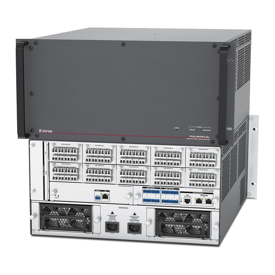
About this Guide This guide contains installation, configuration, and operating information for the Extron FOX3 Matrix 80x Switcher. This customizable matrix switcher supports up to 80 inputs and outputs from Extron fiber optic endpoints (transmitters and receivers). About the FOX3 Matrix Switchers The FOX3 matrix switcher (see figure 1... - Page 10 The matrix switcher is housed in a rack-mountable, 5U high metal enclosure with mounting flanges for a standard 19-inch rack. The switcher has two IEC power input connectors to provide 100 VAC to 240 VAC, 50-60 Hz power to the unit. FOX3 Matrix 80x Switchers • Introduction...
-
Page 11: Fiber Optic I/O Boards
I/O boards to up to an 80-input by 80-output matrix. NOTE: Multimode and singlemode fiber optic I/O boards can be mixed in a FOX3 matrix switcher, but be sure to connect the proper transmission mode fiber cables to each board. FOX3 Matrix 80x Switchers • Introduction... -
Page 12: Features
• Secure partitioning segregates sources and destinations in a secure environment — Secure partitioning enables the FOX3 Matrix 80x to be partitioned into smaller sub-switchers for segregating sources and destinations. Sources can only be routed to destinations within the same partition. - Page 13 Multimode and Singlemode I/O boards available — The FOX3 Matrix 80x is • configurable with a mix of multimode and singlemode versions of the FOX3 Matrix 80x I/O 88 boards, so that both short and long haul transmission can be supported.
-
Page 14: Installation
Front panel USB Configuration port (see Front Panel Configuration Port • page 17). … Power Connect power (see on page 13). … Test the switcher by creating a tie (see Output switching on page 24). FOX3 Matrix 80x Switchers • Installation... -
Page 15: Rear Panel Boards, Cabling, And Features
G G G G G H H H H H I I I I I F F F F F Figure 2. FOX3 Matrix 80x Fiber Optic Matrix Switcher Rear Panel Fiber optic boards with connectors and LEDs Power connectors Replaceable fans Audio Inputs... -
Page 16: I/O Boards
In connector on a FOX transmitter. Output LED — See Fiber optic I/O board LED indications on page 9. INPUTS Receiving Unit OUT* Optional for return data FOX3 Matrix 80x Switchers • Installation... -
Page 17: Cooling Fan Assembly
100 Mbps (100Base-T — Fast Ethernet) — Requires CAT 5e UTP or STP cable at minimum. • 1000 Mbps (1000Base-T — IEEE 802.3ab) half-duplex and full-duplex Ethernet — Requires CAT 5, CAT 5e, CAT 6, or CAT 7 UTP or STP cable. FOX3 Matrix 80x Switchers • Installation... -
Page 18: Remote Port
NOTE: The factory configured passwords for all accounts on this device have been set to the device serial number. In the event of a complete system reset, the passwords convert to the default, which is extron for the Admin and User. FOX3 Matrix 80x Switchers • Installation... -
Page 19: Power Supply Modules
Extron FOX3 transmitters and receivers and other Dante-compatible audio devices. Download and install the latest version of Dante Controller for Windows from the Dante Software/Firmware Installation Controller product page (see on page 30). FOX3 Matrix 80x Switchers • Installation... -
Page 20: Operation
FOX3 MATRIX 80x FIBER OPTIC DIGITAL MATRIX SWITCHER Figure 8. Front Panel, FOX3 Matrix 80x Switcher USB Config port — If desired, connect a control system or computer to the front panel Configuration port . NOTE: A front panel Configuration port connection and a rear panel Remote port connection can both be active at the same time. -
Page 21: Power
Matrix Operations The FOX3 Matrix 80x can be operated in one of two modes: Port mode and System Mapping mode. NOTE: The FOX3 matrix is initially in Port mode when it is powered for the first time. -
Page 22: Reset Operations
Analysez minutieusement les différents modes de réinitialisation. Appliquer le mauvais mode de réinitialisation peut causer une perte inattendue de la programmation de la mémoire flash, une reconfiguration des ports ou une réinitialisation du processeur. FOX3 Matrix 80x Switchers • Operation... - Page 23 In the event of a complete system reset, the passwords convert to the default, which is extron for the Admin and User (see Roles and Permissions Panel on page 45 to change a password). FOX3 Matrix 80x Switchers • Operation...
-
Page 24: Performing Soft System Resets (Resets 3, 4, And 5)
Check the cabling and make corrections as necessary. Call the Extron S3 Sales and Technical Support Hotline if necessary (see the contact numbers on the last page of this guide for the nearest Extron office). FOX3 Matrix 80x Switchers • Operation... -
Page 25: Sis Configuration And Control
Connect to a host computer for configuration using SIS commands via an SSH client such as PuTTY, available at www.putty.org, and IP address 203.0.113.22 and port 22023 (see Establishing a Connection on page 18 to connect to PuTTY). FOX3 Matrix 80x Switchers • SIS Configuration and Control... -
Page 26: Ethernet (Lan) Port
If connecting via the USB port, the IP address is 203.0.113.22. • Enter 22023 in the Port field ( If this is the first time connecting with this device, the PuTTY Security Alert pop-up window opens (see figure 12 on page 19). FOX3 Matrix 80x Switchers • SIS Configuration and Control... - Page 27 If the login and password are incorrect, the Login as prompt returns. Enter the • administrator or user name and password again. FOX3 Matrix 80x Switchers • SIS Configuration and Control...
-
Page 28: Using Verbose Mode
The switcher does not expect a response from the host, but, for example, the host program might request a new status. (C) COPYRIGHT 2020, Extron Electronics, FOX3 Matrix 80x, Vx.xx, 60-nnnn-01 {day,date,time} The switcher issues the copyright message when it is first powered on or when a connection via Internet protocol (IP) is established. -
Page 29: Switcher Error Responses
Device not present — Maximum number of connections exceeded — Bad filename or file not found NOTE: If the unit does not support or recognize the entered commands, no response will be issued. FOX3 Matrix 80x Switchers • SIS Configuration and Control... -
Page 30: Using The Command And Response Tables
Unless stated otherwise, SIS commands are not case sensitive. Special Characters The switcher does not accept these characters as the name of the switcher, passwords, or locally created file names. All alpha-numeric characters permitted except , and “space”. FOX3 Matrix 80x Switchers • SIS Configuration and Control... -
Page 31: System Definitions
Volume adjustment range — 0 to 100 (approximately 1 dB per step 0% to 100% [default]) SFP modules installed — 0 = No SFP 1 = MM SFP 2 = SM SFP 3 = Unknown SFP FOX3 Matrix 80x Switchers • SIS Configuration and Control... -
Page 32: Command And Response Table For Sis Commands
• In00vAll Untie an input Untie an input from all tied outputs. Outx00 • In • All KEY: = Output number – Maximum number of outputs for your configuration ( = untie) FOX3 Matrix 80x Switchers • SIS Configuration and Control... - Page 33 = Return audio source number – Maximum number of outputs (from a Rx unit, Expansion 40001 40032 50001 50004 Dante , Analog = Analog audio destination number (to Tx) – Maximum number of inputs FOX3 Matrix 80x Switchers • SIS Configuration and Control...
- Page 34 Gain for audio input View audio gain level per input. X1# ] Verbose mode 2/3 KEY: = Audio gain/attenuation value 50001 50004 = Analog audio input number to max number of inputs (Analog FOX3 Matrix 80x Switchers • SIS Configuration and Control...
- Page 35 = Power Supply failed/Installed = Maximum virtual video matrix size inputxoutput (example: 80x80) 30001 30008 40001 40032 = Audio input number – Maximum number of inputs or Expansion , Dante 50001 50004 Analog FOX3 Matrix 80x Switchers • SIS Configuration and Control...
- Page 36 Input 1 and = highest Verbose mode 2/3 In001* numbered installed input. KEY: = Video signal status = No video signal at input, = Video Input signal detected FOX3 Matrix 80x Switchers • SIS Configuration and Control...
-
Page 37: Product Configuration Software
In the event of a complete system reset, the passwords convert to the default, which is extron for the Admin and User (see Roles and Permissions Panel on page 45 to change a password). FOX3 Matrix 80x Switcher • Product Configuration Software... -
Page 38: Software/Firmware Installation
Scroll down to the alphabetic navigation bar (see figure 15). Figure 15. Software Installation Click the appropriate letter to locate the software or firmware. Click Download and follow the on-screen instructions (see figure 16, for PCS). Figure 16. PCS Software Download FOX3 Matrix 80x Switcher • Product Configuration Software... - Page 39 Double-click the executable file and follow the on-screen directions to install the software. For Firmware: To install via PCS, see Update Firmware in the Device Menu on page 38. To install via the internal web pages, see the Firmware Panel on page 44. FOX3 Matrix 80x Switcher • Product Configuration Software...
-
Page 40: Connecting To Pcs
Click in the field to edit (see figure 19) . Click Apply to complete and close. Alternatively, click Apply and Connect to complete and connect to the device. Click Cancel to close the box without changes. Figure 19. Communication Settings Box FOX3 Matrix 80x Switcher • Product Configuration Software... -
Page 41: Tcp/Ip Panel
), enter port 4523. NOTE: If the Telnet port number is not known, leave this field blank. PCS will scan for the port. Click the Connect button ( ). A new device tab opens. FOX3 Matrix 80x Switcher • Product Configuration Software... -
Page 42: Offline Device Preview
The New Configuration File dialog box opens (see figure 22). Select the desired device model from the Device Models list (see figure 22). Click the Configure button. A new offline device configuration tab opens. Figure 22. New Configuration File Dialog Box FOX3 Matrix 80x Switcher • Product Configuration Software... -
Page 43: Software Overview
PCS Software Menu Show Expanded Device Tabs Selecting Show Expanded Device Tabs from the Software menu displays the device IP address or connection method in the Device Figure 25. Expanded Device Tab tab. FOX3 Matrix 80x Switcher • Product Configuration Software... - Page 44 From the Software menu, select Tutorial. The Tutorial dialog box opens. Click the I Get It! button to close the dialog box. Extron PCS Help Open the PCS help file for general PCS operations. From the Software menu, select Extron PCS Help. FOX3 Matrix 80x Switcher • Product Configuration Software...
- Page 45 Click the Close Session(s) and Exit button ( ) to disconnect the software from connected devices, close all offline device tabs, and close the software. Alternatively, click the Cancel button ( ) to leave the software open. FOX3 Matrix 80x Switcher • Product Configuration Software...
- Page 46 Restore to Multiple Devices — Upload a saved configuration file for a FOX3 Matrix 80x to multiple devices on the network. NOTE: The connected devices must be connected via LAN. • FOX3 Matrix 80x Help — Open the FOX3 Matrix PCS Help File in a separate window. FOX3 Matrix 80x Switcher • Product Configuration Software...
- Page 47 NOTE: The connected devices must be connected via LAN. About This Module — Open the About This Module dialog box, with the module part • number and firmware version of the connected device. FOX3 Matrix 80x Switcher • Product Configuration Software...
-
Page 48: Internal Web Pages
In the event of a complete system reset, the passwords convert to the default, which is extron for the Admin and User (see Roles and Permissions Panel on page 45 to change a password). FOX3 Matrix 80x Switcher • Internal Web Page... -
Page 49: Disabling Compatibility Mode
Dante Device Info Panel The panels that can be edited have an EDIT link to click to access the panel. To view general information about the FOX3 Matrix 80x, click the ABOUT link ( About the FOX3 Matrix 80x). FOX3 Matrix 80x Switcher • Internal Web Page... -
Page 50: Device Info Panel
When finished editing, click SAVE to confirm your changes or CANCEL to close the window without making changes. Clicking the X in the upper-right corner of the screen also closes the window. FOX3 Matrix 80x Switcher • Internal Web Page... -
Page 51: Device Status Panel
To set the IP addresses: ) in the Network Settings panel. The Network Click EDIT (see figure 34 [left], Settings panel opens to allow edits (right). Figure 34. Network Settings Panel Edit the network settings as desired: FOX3 Matrix 80x Switcher • Internal Web Page... -
Page 52: Firmware Panel
When the update is completed, the message window closes and the message Firmware Upload Complete appears near the top of the screen. The new firmware filename appears beside Version in the Firmware panel. FOX3 Matrix 80x Switcher • Internal Web Page... -
Page 53: Roles And Permissions Panel
Passwords can be changed but they cannot be removed entirely. The FOX3 must have a passwords at all times. These fields cannot be blank. Figure 38. Passwords Dialog Box FOX3 Matrix 80x Switcher • Internal Web Page... -
Page 54: Dante Device Info Panel
FOX3 Matrix 80x, such as the firmware version, copyright, part number, licenses, patents and web page version. Click on the View the End User License Agreement link to view the user license. Figure 40. About Panel FOX3 Matrix 80x Switcher • Internal Web Page... -
Page 55: Maintenance And Modifications
• L’installation et l’entretien doivent être effectués par le personnel autorisé uniquement. Mounting the Switcher The FOX3 Matrix 80x is housed in a rack-mountable, 5U high metal enclosure with mounting flanges for standard 19-inch wide racks. UL Guidelines The following Underwriters Laboratories (UL) guidelines pertain to the installation of the matrix switcher into a rack. -
Page 56: Mounting Instructions
Typically, singlemode fiber has a yellow jacket and multimode cable has an orange or aqua jacket. • For proper cooling and air flow, boards or blank panels should be installed in all locations during normal switcher operations. FOX3 Matrix 80x Switcher • Maintenacne and Modifications... - Page 57 Gently seat the replacement module into the backplane. Use a screwdriver to tighten the left and right captive panel screws to lock the replacement module in place. FOX3 Matrix 80x Switcher • Maintenacne and Modifications...
-
Page 58: Removing And Installing A Power Supply Module
Gently slide the power supply into the enclosure until the module meets resistance. Gently seat the power supply in the backplane. Use a screwdriver to tighten the left and right captive panel screws to secure the power supply in place. FOX3 Matrix 80x Switcher • Maintenacne and Modifications... -
Page 59: Removing And Installing A Fan Assembly
Removing and Installing a Fan Assembly The FOX3 Matrix 80x has one replaceable fan assembly with three fans. If a fan fails, the fan assembly should be replaced at the earliest opportunity. NOTES: • The fan assemby is hot-swappable. It can be removed or installed without powering down the switcher. - Page 60 Extron Electronics makes no further warranties either expressed or implied with respect to the product and its quality, performance, merchantability, or fitness for any particular use. In no event will Extron Electronics be liable for direct, indirect, or consequential damages resulting from any defect in this product even if Extron Electronics has been advised of such damage.