Table of Contents
Advertisement
Quick Links
MM91 Series User Manual
NO. G03-MM9100-F
Rev: 1.0
Release date: Sep 20, 2019
Trademark:
* Specifications and Information contained in this documentation are furnished for information use only, and are subject
to change at any time without notice, and should not be construed as a commitment by manufacturer.
Advertisement
Table of Contents

Related Manuals for JETWAY MM91 Series


Summary of Contents for JETWAY MM91 Series
- Page 1 MM91 Series User Manual NO. G03-MM9100-F Rev: 1.0 Release date: Sep 20, 2019 Trademark: * Specifications and Information contained in this documentation are furnished for information use only, and are subject to change at any time without notice, and should not be construed as a commitment by manufacturer.
-
Page 2: Table Of Contents
TABLE OF CONTENT ENVIRONMENTAL SAFETY INSTRUCTION ................iii ENVIRONMENTAL PROTECTION ANNOUCEMENT ..............iii USER’S NOTICE ........................iv MANUAL REVISION INFORMATION ..................iv ITEM CHECKLIST ........................iv CHAPTER 1 INTRODUCTION OF THE MOTHERBOARD SPECIFICATION ......................1 LAYOUT DIAGRAM ....................2 CHAPTER 2 HARDWARE INSTALLATION JUMPER SETTING .....................6 CONNECTORS AND HEADERS ................10 2-2-1 REAR I/O BACK PANEL CONNECTORS .............10 2-2-2... -
Page 3: Environmental Safety Instruction
Environmental Safety Instruction Avoid the dusty, humidity and temperature extremes. Do not place the product in any area where it may become wet. 0 to 40 centigrade is the suitable temperature. (The figure comes from the request of the main chipset) ... -
Page 4: User's Notice
USER’S NOTICE COPYRIGHT OF THIS MANUAL BELONGS TO THE MANUFACTURER. NO PART OF THIS MANUAL, INCLUDING THE PRODUCTS AND SOFTWARE DESCRIBED IN IT MAY BE REPRODUCED, TRANSMITTED OR TRANSLATED INTO ANY LANGUAGE IN ANY FORM OR BY ANY MEANS WITHOUT WRITTEN PERMISSION OF THE MANUFACTURER. -
Page 5: Chapter 1 Introduction Of The Motherboard
Chapter 1 Introduction of the Motherboard 1-1 Specification Spec Description Design m-ATX form factor; PCB size: 24.4 x24.4 cm Chipset Intel ® H110 Express Chipset Supports Intel ® Core™ i7, Core™ i5, Core™ i3 series, CPU Socket Pentium ®... -
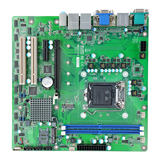
Page 6: Layout Diagram
1* Front panel header 1* Speaker header+ 1* POWER LED header 1* Vertical type connector USB 2.0 port 1* 9-pin front panel USB 2.0 header for 2* expansion USB 2.0 port 1* PS/2 KB & MS header ... - Page 7 Motherboard Internal Diagram ATX 12V Power Connector CPUFAN Header SYSFAN1 Header Serial Ports (COM1/COM2) USB 2.0 Ports DDR4 over HDMI Port DIMM Slot x 2 LGA 1151 VGA Port CPU Socket over DVI-D Port ATX Power Connector RJ-45 LAN Ports Over USB 3.0 Ports M.2 Socket 3 Connector SYSFAN2 Header...
- Page 8 Motherboard Jumper Position JPCOM2 JPCOM1 JATX_AT JPCOM5 JPCOM3 COPEN JBAT JPCOM6 JPCOM4 Jumper Jumper Name Description JPCOM1 COM1 Port Pin9 Function Select 4-pin Block JPCOM2 COM2 Port Pin9 Function Select 4-pin Block JPCOM3 COM3 Header Pin9 Function Select 4-pin Block JPCOM4 COM4 Header Pin9 Function Select 4-pin Block...
- Page 9 Connectors Connector Name ATXPWR ATX Main Power Connector ATX12V ATX 12V Power Connector COM1_2 Serial Port COM Connector X2 USB1 USB 2.0 Port Connector X2 USB20_V USB 2.0 Vertical Port Connector X1 HDMI HDMI Port Connector CRT_DVI Top: VGA Port Connector Bottom: DVI-D Port Connector UL1/UL2 Top:RJ-45 LAN Connector X2...
-
Page 10: Chapter 2 Hardware Installation
Chapter 2 Hardware Installation 2-1 Jumper Setting JPCOM1 (4-pin): COM1 Port Pin9 Function Select JPCOM1→COM1 Port 2 4 6 2 4 6 1 3 5 1 3 5 2-4 Closed: 3-4 Closed: 4-6 Closed: RI=RS232 RI= 5V RI= 12V JPCOM2 (4-pin): COM2 Port Pin9 Function Select JPCOM2→COM2 Port 2 4 6 2 4 6... - Page 11 JPCOM4 (4-pin): COM4 Header Pin9 Function Select JPCOM4→COM4 Header 2 4 6 2 4 6 1 3 5 1 3 5 2-4 Closed: 3-4 Closed: 4-6 Closed: RI=RS232 RI= 5V RI= 12V JPCOM5 (4-pin): COM5 Header Pin9 Function Select JPCOM5→COM5 Header 2 4 6 2 4 6 1 3 5...
- Page 12 JATX_AT(3-pin): ATX Mode/AT Mode Select* → JATX_AT(3-pin) ATX/AT Mode Select Pin 1 1-2 Open: ATX Mode Selected(Default) Pin 1 2-3 Closed: AT Mode Selected *ATX Mode Selected: Press power button to power on after power input ready; AT Mode Selected: Directly power on as power input ready. COPEN (2-pin): Case Open Message Display Select Pin(1-2) of COPEN →...
- Page 13 Pin(1-2)of JBAT (4-pin): Clear CMOS RAM Function Settings Pin(1-2) of JBAT → Clear CMOS Pin 1 1-2 Open: Normal(Default) Pin 1 1-2 Closed: Clear CMOS RAM Settings Pin(3-4)of JBAT (4-pin): DFDS Override Pin(3-4) of JBAT → DFDS Override Pin 1 3-4 Open: Normal (Default) Pin 1 3-4 Closed: DFDS Override...
-
Page 14: Connectors And Headers
Connectors and Headers 2-2-1 Rear I/O Back Panel Connectors *Refer to Page-2. Icon Name Function Mainly for user to connect external MODEM or other devices that supports Serial Port Serial Communications Interface. *Note: COM1 supports RS232/422/485 function. To connect display device that support HDMI HDMI Port specification. -
Page 15: Motherboard Internal Connectors
2-2-2 Motherboard Internal Connectors (1) ATXPWR (24-pin block): Main Power Connector ATX Power Supply connector: This is a new defined 24-pins connector that usually comes with ATX case. The ATX Power Supply allows using soft power on momentary switch that connect from the front panel switch to 2-pins Power On jumper pole on the motherboard. - Page 16 (2) ATX12V (8-pin block): 12V Power Connector This is a new defined 8-pin connector that usually comes with ATX Power Supply that supports extra 12V voltage to maintain system power consumption. Without this connector might cause system unstable because the power supply can not provide sufficient current for system.
- Page 17 (4) M2: M2 Socket 3 Connector This M2 Socket 3 connector support compatible type 2242/2260/2280/22110 SATA SSD module. M.2 Socket 3 Connector M.2 Module Installation Guide 1. Prepare compatible M.2 SATA or M.2 SSD card. Deferent type of cards has different length.
-
Page 18: Header Pin Definition
2-2-3 Header Pin Definition FP_AUDIO (9-pin): Line-Out, MIC-In Header This header is connected to Front Panel Line-out, MIC connector with cable. Pin 1 SPDIF (2-pin): HDMI-SPDIF Out header Pin1 LAN1_LED/ LAN2_LED (2-pin): LANLED Header Pin1... - Page 19 COM10/9/8/76/5/4/3 (9-pin): Serial Port Header Pin6 Pin1 GPIO_CON (10-pin): GPIO Header Pin 1 JW_FP (9-pin): Front Panel Header Pin 1...
- Page 20 SPK_LED (7-pin): PWR LED Header & Speaker Header SPEAK- PWR LED- VSB_LED SPEAK+ PWR LED+ Pin 1 FP_USB1(9-pin): USB 2.0 Port Headers Pin 1 PS2KBMS (6-pin): PS/2 Keyboard & Mouse Header Pin1...
- Page 21 SMBUS (5-pin): SM BUS Header SMBUS_ALERT SMBUS_DATA Pin1 SMBUS_CLK SYSFAN1/CPUFAN/SYSFAN2 (4-pin): FAN Headers Pin1 Dual Channel Memory Installation config Slot 1 Slot 2 install install install install...
- Page 22 Notice! For dual channel installation, you need to install the same brand, speed, size and type memory module. It is unable to activate dual channel feature if you install only one memory module. Slot order can be from left-to-right or right-to-left, and it must be installed in pairs. ...
-
Page 23: Chapter 3 Introducing Bios
Chapter 3 Introducing BIOS Notice! The BIOS options in this manual are for reference only. Different configurations may lead to difference in BIOS screen and BIOS screens in manuals are usually the first BIOS version when the board is released and may be different from your purchased motherboard. Users are welcome to download the latest BIOS version form our official website. -
Page 24: Bios Menu Screen
BIOS Menu Screen The following diagram show a general BIOS menu screen: Menu Bar General Help Items Current Setting Value Menu Items Function Keys Function Keys In the above BIOS Setup main menu of, you can see several options. We will explain these options step by step in the following pages of this chapter, but let us first see a short description of the function keys you may use here: ... -
Page 25: Menu Bars
Press [F1] to pop up a small help window that describes the appropriate keys to use and the possible selections for the highlighted item. To exit the Help Window, press <Esc>. 3-5 Menu Bars There are six menu bars on top of BIOS screen: Main To change system basic configuration Advanced... -
Page 26: Advanced Menu
3-7 Advanced Menu CPU Configuration ► Press [Enter] to view current CPU configuration and make settings for the following sub-items: Hyper-Threading The optional settings: [Disabled]; [Enabled]. When set as [Disabled] only one thread per enabled core is enabled. [Enabled]: for Windows XP and Linux (OS optimized for Hyper-Threading Technology). - Page 27 The optional settings are: [C0/C1]; [C2]; [C3]; [C6]; [C7]; [C7S]; [C8]; [C9]; [C10]; [CPU Default]; [Auto]. SATA Configuration ► Press [Enter] to make settings for the following sub-items: SATA Controller(s) The optional settings are: [Enabled]; [Disabled]. When set as [Enabled], the following items shall appear: SATA Mode Selection Use this item to determine how SATA controller(s) operate.
- Page 28 Wake-up Function Settings ► Press [Enter] to make settings for the following sub-items: Wake-up System with Fixed Time Use this item to enable or disable system wake on alarm event. The optional settings: [Disabled]; [Enabled]. When set as [Enabled], system will wake on the Hour/Minute/Second specified. Wake-up System with Dynamic Time Use this item to enable or disable system wake on alarm event.
- Page 29 RS422/RS485=10Mbps]. Serial Port FIFO Mode The optional settings are: [16-Byte FIFO]; [32-Byte FIFO]; [64-Byte FIFO]; [128- Byte FIFO]. ► Serial Port 2 Configuration/Serial Port 3 Configuration/Serial Port 4 Configuration/Serial Port 5 Configuration/Serial Port 6 Configuration Press [Enter] to make settings for the following sub-items: Serial Port Use this item to enable or disable serial port (COM).
- Page 30 Press [Enter] to view current hardware health status, make further settings in ‘SmartFAN Configuration’. ► SmartFAN Configuration Press [Enter] to make settings for SmartFan Configuration: SmartFAN Configuration CPUFAN/SYSFAN1 Smart Mode The optional settings are: [Disabled]; [Enabled]. When set as [Enabled], the following sub-items shall appear: CPUFAN/SYSFAN1 Full-Speed Temperature Use this item to set CPUFAN/SYSFAN1 full speed temperature.
- Page 31 The optional settings are: [VT100]; [VT100+]; [VT-UTF8]; [ANSI]. Bits per second The optional settings are: [9600]; [19200]; [38400]; [57600]; [115200]. Data Bits The optional settings are: [7]; [8]. Parity The optional settings are: [None]; [Even]; [Odd]; [Mark]; [Space]. Stop Bits The optional settings are: [1];...
- Page 32 *This item may or may not show up, depending on different configuration. Stop Bits The default setting is: [1]. *This item may or may not show up, depending on different configuration. Network Stack Configuration ► Press [Enter] to go to ‘Network Stack’ screen to make further settings. Network Stack Use this item to enable or disable UEFI Network Stack.
- Page 33 The optional settings are: [Enabled]; [Disabled]; [Auto]. [Enabled]: To enable legacy USB support. [Disabled]: to keep USB devices available only for EFI specification, [Auto]: To disable legacy support if no USB devices are connected. XHCI Hand-off This is a workaround for OSes without XHCI hand-off support. The XHCI ownership change should be claimed by XHCI driver.
-
Page 34: Chipset Menu
3-8 Chipset Menu System Agent (SA) Configuration ► Press [Enter] to make settings for the following sub-items: VT-d The optional settings are: [Enabled]; [Disabled]. ► Graphics Configuration Press [Enter] to make further settings for Graphics Configuration. Graphics Configuration Primary Display Use this item to select which of graphics device should be primary display. - Page 35 Primary IGFX Boot Display Use this item to select the video device which will be activated during POST. This has no effect if external graphics present. Secondary boot display selection will appear based on your selection. The optional settings are: [VBIOS Default]; [HDMI]; [DVI]; [CRT]. * Note: When set as [HDMI], [DVI] or [CRT], user can make further settings in ‘Second IGFX Boot Display’.
-
Page 36: Security Menu
3-9 Security Menu Security menu allow users to change administrator password and user password settings. Administrator Password Press [Enter] to create new administrator password. Press again to confirm the new administrator password. User Password Press [Enter] to create new user password. Press again to confirm the new user password. -
Page 37: Boot Menu
HDD is GPT then enable UEFI boot options, otherwise disable. The optional settings are: [Disabled]; [Enabled]. Hard Drive BBS Priorities Use this item to set the order of the legacy devices in this group. The optional settings are: [P0:JETWAY]; [Disabled]. -
Page 38: Save & Exit Menu
3-11 Save & Exit Menu Save Options: Save Changes and Reset This item allows user to reset the system after saving the changes. Discard Changes and Reset This item allows user to reset the system without saving any changes. Default Options: Restore Defaults Use this item to restore /load default values for all the setup options.