Table of Contents
Advertisement
Quick Links
Technical Manual
Of
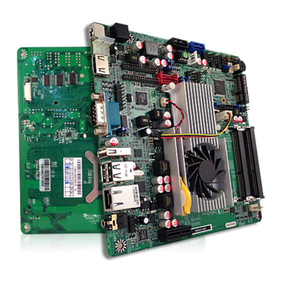
Intel 1047UE CPU + Intel HM65 Chipset
Based
Mini-ITX M/B
NO.G03-NF9K-F
Revision: 1.0
Release date: August 27, 2013
Trademark:
* Specifications and Information contained in this documentation are furnished for information use only, and are
subject to change at any time without notice, and should not be construed as a commitment by manufacturer.
Advertisement
Table of Contents

Related Manuals for JETWAY MBD-J-JNF9KC-1047


Summary of Contents for JETWAY MBD-J-JNF9KC-1047
- Page 1 Technical Manual Intel 1047UE CPU + Intel HM65 Chipset Based Mini-ITX M/B NO.G03-NF9K-F Revision: 1.0 Release date: August 27, 2013 Trademark: * Specifications and Information contained in this documentation are furnished for information use only, and are subject to change at any time without notice, and should not be construed as a commitment by manufacturer.
- Page 2 Environmental Protection Announcement Do not dispose this electronic device into the trash while discarding. To minimize pollution and ensure environment protection of mother earth, please recycle.
-
Page 3: Table Of Contents
TABLE OF CONTENT ENVIRONMENTAL SAFETY INSTRUCTION................iv USER’S NOTICE ........................v MANUAL REVISION INFORMATION ..................v ITEM CHECKLIST ........................v CHAPTER 1 INTRODUCTION OF THE MOTHERBOARD FEATURE OF MOTHERBOARD................1 SPECIFICATION ......................2 LAYOUT DIAGRAM....................4 CHAPTER 2 HARDWARE INSTALLATION JUMPER SETTING ..................... -
Page 4: Environmental Safety Instruction
Environmental Safety Instruction Avoid the dusty, humidity and temperature extremes. Do not place the product in any area where it may become wet. 0 to 60 centigrade is the suitable temperature. (The figure comes from the request of the main chipset) Generally speaking, dramatic changes in temperature may lead to contact malfunction and crackles due to constant thermal expansion and contraction from the welding spots’... -
Page 5: User's Notice
USER’S NOTICE COPYRIGHT OF THIS MANUAL BELONGS TO THE MANUFACTURER. NO PART OF THIS MANUAL, INCLUDING THE PRODUCTS AND SOFTWARE DESCRIBED IN IT MAY BE REPRODUCED, TRANSMITTED OR TRANSLATED INTO ANY LANGUAGE IN ANY FORM OR BY ANY MEANS WITHOUT WRITTEN PERMISSION OF THE MANUFACTURER. -
Page 6: Chapter 1 Introduction Of The Motherboard
Chapter 1 Introduction of the Motherboard Feature of Motherboard ® ® Intel Generation Celeron 1047UE dual-core CPU+ Intel HM65 express chipset, with low power consumption never denies high performance Support 2* DDRIII 1066/1333/1600 MHz SO-DIMM up to 16GB Support 1* Mini-PCIE/Mini-SATA selectable connector Support HDMI Video Output Integrated with 2* 24-bit dual-channel LVDS headers Support 1 * Serial ATAII (3Gb/s) &... -
Page 7: Specification
Specification Spec Description Design Mini-ITX form factor 6 layers ; PCB size: 17.0 x17.0cm ® Intel Generation Celeron 1047UE Dual Core CPU Embedded CPU (1.4GHz) ® Intel HM65 Express chipset Chipset 2 * SO-DIMM DDRIII slots support DDRIII 1066/1333/1600 Memory Slot MHz SO-DIMM , total maximum to 16GB Support dual-channel function 1 * SATAII (3Gb/s) connector... - Page 8 Internal I/O Connectors& Headers: 1 *2-pin internal DC-in Power connector SATA power-out connector x1 Fan connector x3 Front audio header x1 LAN activity LED header x1 Serial port header x4 (*COM1 header is optional for NF9KV series) Serial port header x3 (Optional for NF9KC series) VGA port header x1 (*VGA1 header is optional for NF9KC series) J2: Power LED header + Speaker header x1...
-
Page 9: Layout Diagram
Layout Diagram NF9KV Rear IO Diagram USB 2.0 Ports VGA Port RJ-45 LAN Port HDMI Port 9~24V DC Power Connector USB 2.0 Port Line Out/ Optical SPDIF_Out Connector NF9KC Rear IO Diagram USB 2.0 Ports COM1 Port RJ-45 LAN Port HDMI Port 9~24V DC Power... - Page 10 NF9KV: Motherboard Internal Diagram Internal DC Power Serial Port Connector SATAII Port Headers SATAIII Port (DCCN1) (SATA2) Power LED + (COM2/3/4) (SATA1) Speaker Header (J2) Front Panel Header 9~24 VDC SATA HDD Power Connector Power Connector SYSFAN1 Header INVERTER1 (J1) LVDS1 Header USB 2.0 Headers HDMI Port...
- Page 11 NF9KC: Motherboard Internal Diagram Internal DC Power Serial Port Connector SATAII Port Headers SATAIII Port (DCCN1) (SATA2) Power LED + (COM2/3/4) (SATA1) Speaker Header (J2) Front Panel Header 9~24V DC SATA HDD Power Connector Power Connector SYSFAN1 Header INVERTER1 (J1) LVDS1 Header USB 2.0 Headers HDMI Port...
- Page 12 Motherboard Jumper Position JCOMP4 JBAT COPEN1 AT_MODE1 JCOMP1 Note: The above illustration diagram is from NF9KV. NF9KC series has the same jumpers at the same marked positions. The following diagrams for illustrations are from NF9KV as well, unless otherwise noted.
- Page 13 Jumper Jumper Name Description JBAT CMOS Clear Function Setting 3-pin Block LVDS1 VCC 3.3V/5V/12V Select 4-pin Block LVDS2 VCC 3.3V/5V/12V Select 4-pin Block INVERTER2 VCC 3.3V/5V/VIN Select 4-pin Block INVERTER1 VCC 3.3V/5V/VIN Select 4-pin Block MINI_CARD Slot Power 3.3V/3.3VSB Select 3-Pin Block JCOMP1 COM1 Port/Header Pin9 Function Select...
- Page 14 Headers Header Name Description FP_AUDIO Front Panel Audio Header 9-Pin Block NIC_LED2 LAN Activity LED Header 2-Pin Block VGA1 (for NF9KC) Video Graphic Attach Header 15-Pin Block LVDS1/LVDS2 LVDS Header 30-Pin Block INVERTER1/INVERT LVDS Inverter 8-Pin Block COM1 Serial Port Headers 9-Pin Block (for NF9KV);...
-
Page 15: Chapter 2 Hardware Installation
Chapter 2 Hardware Installation 2-1 Jumper Setting (1) JBAT (3-pin): Clear CMOS JBAT 1-2 Closed: Normal; 2-3 Closed:Clear CMOS CMOS Clear Setting (2) JP1 (4-pin): LVDS1 VCC 3.3V/5V /12V Select JP1→LVDS1 2 4 6 2 4 6 1 3 5 1 3 5 2-4 Closed: LVDS1 3-4 Closed: LVDS1... - Page 16 (3) JP2 (4-pin): LVDS2 VCC 3.3V/5V /12V Select JP2→LVDS2 2 4 6 2 4 6 1 3 5 1 3 5 6-4 Closed: LVDS2 2-4 Closed: LVDS2 3-4 Closed: LVDS2 VCC= 12V; VCC= 3.3V VCC= 5V; (4) JP3 (4-pin): INVERTER2 VCC 3.3V/5V/VIN Select JP3→INVERTER2 2-4 Closed: 3-4 Closed:...
- Page 17 (5) JP4 (4-pin): INVERTER1 VCC 3.3V/5V/VIN Select JP4→INVERTER1 2-4 Closed: 3-4 Closed: 6-4 Closed: Inverter Backlight Inverter Backlight Inverter Backlight VCC= 5V; VCC= 12V; VCC= VIN. (6) JP5 (3-pin): MINI_CARD Slot Power 3.3V / 3.3V SB Select 1-2 Closed:MINI_CARD 2-3 Closed:MINI_CARD Power VCC = 3.3V;...
- Page 18 (7) JCOMP1 (4-pin): COM1 Port / Header Pin9 Function Select JCOMP1→COM1 2 4 6 2 4 6 1 3 5 1 3 5 2-4 Closed: RS232 3-4 Closed:+ 5V; 6-4 Closed: + 12V. (8) JCOMP4 (4-pin): COM4 Header Pin9 Function Select JCOMP4→COM4 2 4 6 2 4 6...
- Page 19 AT_MODE1 1-2 Open: Normal; 1-2 Short: AT_Mode Select. (10)COPEN1 (2-pin): Case Open Message Display function select Pin 1-2 shorted: Case open display function enabled. In this case if you case is removed, next time when you restart your computer a message will be displayed onscreen to inform you of this.
-
Page 20: Connectors And Headers
Connectors and Headers 2-2-1 Connectors (1) Rear I/O Connectors NF9KV Rear IO Diagram USB 2.0 Ports VGA Port RJ-45 LAN Port HDMI Port 9~24V DC Power Connector USB 2.0 Port Line Out/ Optical SPDIF_Out Connector NF9KC Rear IO Diagram USB 2.0 Ports COM1 Port RJ-45 LAN Port HDMI Port... - Page 21 (2) DC Power Connector (2-pin block):DCCN1 Pin1 Pin No. Definition +12 VIN *Note: The board has a DC 9-24V power connector (J1) in I/O back panel and an internal ATX12V (DCCN1) power connector. User can only connect one type of compatible power supply to one of them.
- Page 22 (4) SATA1: SATAIII Port connector SATA1 port is a SATAIII port that supports 6GB/s transfer rate. Pin No. Definition (5) SATA2: SATAII Port connector SATA2 port is a SATAII port that supports 3 GB/s transfer rate. Pin No. Definition...
-
Page 23: Headers
(6) CPUFAN, SYSFAN1, SYSFAN2: FAN Headers (4-pin) SYSFAN1 Control Fan Speed +12V Fan Power Pin1 Pin1 CPUFAN/SYSFAN2 2-2-2 Headers (1) FP_AUDIO (9-pin): Front panel audio LINEOUT2-L S ENSE-FB LINE OUT2-R MIC2-R MIC2-L Pin 1... - Page 24 (2) NIC_LED2 (2-pin): LAN Activity LED Header Pin1 (3) * VGA1 (15-pin): VGA Header KE Y SMBUS_CLK HSYNC V SYNC S MBUS_DATE VCC_ V GA G ND G ND BLUE GREEN Pin 1 *Note: VGA1 header is optional for NF9KC Series. The above diagram is from NF9KC.
- Page 25 (4) LVDS1/LVDS2 (30-pin): 24-bit dual channel LVDS Header Pin 1 Pin 2 LVDS1 Header Pin 1 Pin 2 LVDS2 Header Pin NO. Pin Define Pin NO. Pin Define Pin 1 LVDSB_DATAN3 Pin 2 LVDSB_DATAP3 Pin 3 LVDS_CLKBN Pin 4 LVDS_CLKBP Pin 5 LVDSB_DATAN2 Pin 6...
- Page 26 (5) INVERTER1 (8-Pin): LVDS1 Inverter Header Pin No. Definition Backlight Enable Backlight Duty Backlight Power Backlight Power Pin 1 Backlight+ SW Backlight- SW INVERTER1 *Note: Only LVDS1 supports panel backlight adjustment, with the support from INVERTER1. (6) INVERTER2 (8-Pin): LVDS2 Inverter Header Pin No.
- Page 27 (7) *COM1/COM2/COPM3/COM4 (9-pin): Serial Port Headers Pin 1 SOUT *Note: COM1 header is optional for NF9KV Series. (8) J2 (7-pin): PWRLED Header & Speaker Header Pin 1 SP K+ PWRLE D+ P WRLED- PWRLE D- SPK-...
- Page 28 (9) JW-FP1 (9-pin): Front Panel Header Pin 1 (10) F_USB1/F_USB2 (9-pin): USB 2.0 Port Header Pin 1 DATA- DATA- DATA+ DATA+...
- Page 29 (11) PS2_CON1 (6-pin): PS/2 Keyboard & Mouse Header Pin1 (12) GPIO_CON1(10-pin): GPIO Header Pin 1...
-
Page 30: Chapter 3 Introducing Bios
Chapter 3 Introducing BIOS Notice! The BIOS options in this manual are for reference only. Different configurations may lead to difference in BIOS screen and BIOS screens in manuals are usually the first BIOS version when the board is released and may be different from your purchased motherboard. Users are welcome to download the latest BIOS version form our official website. -
Page 31: Bios Menu Screen
BIOS Menu Screen The following diagram show a general BIOS menu screen: Menu Bar General Help Items Current Setting Value Menu Items Function Keys BIOS Menu Screen Function Keys In the above BIOS Setup main menu of, you can see several options. We will explain these options step by step in the following pages of this chapter, but let us first see a short description of the function keys you may use here: Press←→... -
Page 32: Getting Help
Press ↑↓ (up, down) to choose, in the main menu, the option you want to confirm or to modify. Press <Enter> to select. Press <+>/<–> keys when you want to modify the BIOS parameters for the active option. [F1]: General help. [F2]: Previous value. -
Page 33: Main Menu
User can press the right or left arrow key on the keyboard to switch from menu bar. The selected one is highlighted. Main Menu Main menu screen includes some basic system information. Highlight the item and then use the <+> or <-> and numerical keyboard keys to select the value you want in each item. -
Page 34: Advanced Menu
System Date Set the date. Please use [Tab] key to switch between data elements. System Time Set the time. Please use [Tab] key to switch between time elements. 3-7 Advanced Menu ► CPU Configuration Press [Enter] user can have a view of CPU basic information and make settings in sub-items. - Page 35 Limit CPUID Maximum The optional settings are: [Disabled]; [Enabled]. This item should be set as [Disabled] for Windows XP. Execute Disable Bit The optional settings are: [Disabled]; [Enabled]. Intel Virtualization Technology The optional settings: [Enabled]; [Disabled]. When set as [Enabled], a VHM can utilize the additional hardware capabilities provided by Vanderpool Technology.
- Page 36 ► PCH-FW Configuration Press [Enter] to view ME information and configure Management Engine technology parameters. ► Firmware Update Configuration Press [Enter] to make settings for ‘ME FW Image RE-Flash’. User can use this item to enable or disable ME FW Image Re-Flash function. ►...
- Page 37 Power-up delay in seconds, the delay range in from 1 to 40 seconds in one second increments. ► F81866 Super IO Configuration F81866 Super IO Configuration ► Serial Port 1 Configuration / Serial Port 4 Configuration Press [Enter] to make settings for the following items: Serial Port Use this item to enable or disable serial port (COM).
- Page 38 The optional settings are: [Disabled]; [Enabled]. *When set as [Enabled], the following sub-items shall appear: Change Settings Use this item to select an optimal setting for super IO device. FIFO Mode The optional settings are: [16-Byte FIFO]; [32-Byte FIFO]; [64-Byte FIFO]; [128-Byte FIFO].
- Page 39 ► F81866 H/W Monitor Press [Enter] to view hardware health status, set SmartFAN configuration, select system shutdown temperature and make other relative settings. ► SmartFan Configuration Smart Fan Configuration: CPUFAN / SYSFAN/SYSFAN2 Smart Mode When set as [Enabled], the following sub-items shall appear: CPUFAN Full Speed Temperature / SYSFAN Full Speed Temperature/ SYSFAN2 Full Speed Temperature Use this item to set CPUFAN/SYSFAN/ SYSFAN2 full speed temperature.
- Page 40 Shutdown Temperature Configuration Use this item to select system shutdown temperature. The optional settings are: [Disabled]; [70°C/156°F]; [75°C/164°F]; [80°C/172°F]; [85°C/180°F]; [90°C/188°F]. CPUFAN Type /SYSFAN1 Type /SYSFAN2 Type The optional settings are: [3-Pin]; [4-Pin]. ► Serial Port Console Redirection COM0 Console Redirection The optional settings are: [Disabled];...
- Page 41 The optional settings are: [None]; [Even]; [Odd]; [Mark]; [Space]. Stop Bits The optional settings are: [1]; [2]. Flow Control The optional settings are: [None]; [Hardware RTS/CTS ]. VT-UTF8 Combo Key Support The optional settings are: [Disabled]; [Enabled]. Record Mode The optional settings are: [Disabled]; [Enabled]. Resolution 100x31 The optional settings are: [Disabled];...
- Page 42 ► Console Redirection Settings The settings specify how the host computer and the remote computer (which the user is using) will exchange data. Both computers should have the same or compatible settings. Press [Enter] to go to sub-items: Out-of-Band Mgmt Port Terminal Type The optional settings are: [VT100];...
-
Page 43: Chipset Menu
Use this item to enable or disable system wake on alarm event. The optional settings are: [Disabled]; [Enabled]. When set as [Enabled], system will wake on the hour/min/sec specified. Wake-up System with Dynamic Time Use this item to enable or disable system wake on alarm event. The optional settings are: [Disabled];... - Page 44 ► PCH-IO Configuration Onboard PCIE LAN The optional settings are: [Enabled]; [Disabled]. Mini PCIE The optional settings are: [Enabled]; [Disabled]. Mini PCIE Speed The optional settings are: [Auto];[Gen1]; [Gen2]. Azalia Use this item to control detection of the Azalia device. The optional settings are: [Enabled];...
- Page 45 This function is only supported when ERP function is disabled. ► System Agent (SA) Configuration ► Graphics Configuration Press [Enter] to further setting graphics configuration. Enable PEG The optional settings are: [Disabled]; [Enabled]; [Auto]. GTT Size The optional settings are: [1MB]; [2MB]. Aperture Size The optional settings are: [128MB];...
- Page 46 The optional settings are: [VBIOS Default]; [CRT]; [HDMI]. Secondary IGFX Boot Display The optional settings are: [Disabled]; [CRT]; [HDMI]. Active LFP The optional settings are: [No LVDS]; [LVDS1]; [LVDS2]; [Both LVDS]. LVDS1 Panel Type Use this item to select LVDS1 display panel resolution. The optional settings are: [VBIOS Default];...
-
Page 47: Boot Menu
3-9 Boot Menu Setup Prompt Timeout Use this item to set number of seconds to wait for setup activation key. Bootup Numlock State Use this item to select keyboard numlock state. The optional settings are: [On]; [Off]. Quiet Boot The optional settings are: [Enabled]; [Disabled]. - Page 48 ► CSM Parameter Press [Enter], user can go to next page to enable or disable ‘Launch CSM’ function. Boot option filter This option controls what device system can boot to. The optional settings are: [UEFI and Legacy]; [Legacy only]; [UEFI only]. Launch PXE OpROM policy This option controls the execution of UEFI and Legacy PXE OpROM.
-
Page 49: Security Menu
3-10 Security Menu Security menu allow users to change administrator password and user password settings. -
Page 50: Save & Exit Menu
3-11 Save & Exit Menu Save Changes and Reset This item allows user to reset the system after saving the changes. Discard Changes and Reset This item allows user to reset the system without saving any changes. Save Changes This item allows user to save changes done so far to any of the setup options. Discard Changes This item allows user to discard changes done so far to any of the setup options. - Page 51 Restore Defaults Use this item to restore /Load default values for all the setup options. Save as User Defaults Use this item to save the changes done so far as user defaults. Restore User Defaults Use this item to restore defaults to all the setup options.