Enterasys G3G124-24 Hardware Installation Manual
G series
Hide thumbs
Also See for G3G124-24:
- Hardware installation manual (70 pages) ,
- Quick reference (2 pages)

Related Manuals for Enterasys G3G124-24


Summary of Contents for Enterasys G3G124-24
- Page 1 ® Enterasys G-Series Ethernet Switch G3G124-24 G3G124-24P G3G170-24 Hardware Installation Guide P/N 9034357-02...
- Page 3 Elektrischer Gefahrenhinweis: Installationen sollten nur durch ausgebildetes und qualifiziertes Personal vorgenommen werden. Enterasys Networks reserves the right to make changes in specifications and other information contained in this document and its web site without prior notice. The reader should in all cases consult Enterasys Networks to determine whether any such changes have been made. The hardware, firmware, or software described in this document is subject to change without notice. IN NO EVENT SHALL ENTERASYS NETWORKS BE LIABLE FOR ANY INCIDENTAL, INDIRECT, SPECIAL, OR CONSEQUENTIAL DAMAGES WHATSOEVER (INCLUDING BUT NOT LIMITED TO LOST PROFITS) ARISING OUT OF OR RELATED TO THIS DOCUMENT, WEB SITE, OR THE INFORMATION CONTAINED IN THEM, EVEN IF ENTERASYS NETWORKS HAS BEEN ADVISED OF, KNEW OF, OR SHOULD HAVE KNOWN OF, THE POSSIBILITY OF SUCH DAMAGES. Enterasys Networks, Inc. 50 Minuteman Road Andover, MA 01810 © 2008 Enterasys Networks, Inc. All rights reserved. Part Number: 9034357‐02 April 2008 ENTERASYS, ENTERASYS NETWORKS, ENTERASYS MATRIX, ENTERASYS NETSIGHT, LANVIEW, WEBVIEW, and any logos associated therewith, are trademarks or registered trademarks of Enterasys Networks, Inc., in the United States and other countries. All other product names mentioned in this manual may be trademarks or registered trademarks of their respective companies. Documentation URL: http://www.enterasys.com/support/manuals Documentacion URL: http://www.enterasys.com/support/manuals Dokumentation im Internet: http://www.enterasys.com/support/manuals...
-
Page 4: Regulatory Compliance Information
Class A ITE Notice WARNING: This is a Class A product. In a domestic environment this product may cause radio interference in which case the user may be required to take adequate measures. Clase A. Aviso de ITE ADVERTENCIA: Este es un producto de Clase A. En un ambiente doméstico este producto puede causar interferencia de radio en cuyo caso puede ser requerido tomar medidas adecuadas. Klasse A ITE Anmerkung WARNHINWEIS: Dieses Produkt zählt zur Klasse A ( Industriebereich ). In Wohnbereichen kann es hierdurch zu Funkstörungen kommen, daher sollten angemessene Vorkehrungen zum Schutz getroffen werden. Product Safety This product complies with the following: UL 60950, CSA C22.2 No. 60950, 2006/95/EC, EN 60950, IEC 60950, EN 60825, 21 CFR 1040.10. Seguridad del Producto El producto de Enterasys cumple con lo siguiente: UL 60950, CSA C22.2 No. 60950, 2006/95/EC, EN 60950, IEC 60950, EN 60825, 21 CFR 1040.10. Produktsicherheit Dieses Produkt entspricht den folgenden Richtlinien: UL 60950, CSA C22.2 No. 60950, 2006/95/EC, EN 60950, IEC 60950, EN 60825, 21 CFR 1040.10. ... - Page 5 This product complies with the following: 47 CFR Parts 2 and 15, CSA C108.8, 2004/108/EC, EN 55022, EN 61000‐3‐2, EN 61000‐3‐3, EN 55024, AS/NZS CISPR 22, VCCI V‐3. Este producto de Enterasys cumple con lo siguiente: 47 CFR Partes 2 y 15, CSA C108.8, 2004/108/EC, EN 55022, EN 55024, EN 61000‐3‐2, EN 61000‐3‐3, AS/NZS CISPR 22, VCCI V‐3. Elektro- magnetische Kompatibilität ( EMC ) Dieses Produkt entspricht den folgenden Richtlinien: 47 CFR Parts 2 and 15, CSA C108.8, 2004/108/EC, EN 55022, EN 61000‐3‐2, EN 61000‐3‐3, EN 55024, AS/NZS CISPR 22, VCCI V‐3. This product complies with the requirements of European Directive, 2002/95/EC, Restriction of Hazardous Substances (RoHS) in Electrical and Electronic Equipment. European Waste Electrical and Electronic Equipment (WEEE) Notice In accordance with Directive 2002/96/EC of the European Parliament on waste electrical and electronic equipment (WEEE): The symbol above indicates that separate collection of electrical and electronic equipment is required and that this product was placed on the European market after August 13, 2005, the date of enforcement for Directive 2002/96/EC. When this product has reached the end of its serviceable life, it cannot be disposed of as unsorted municipal waste. It must be collected and treated separately. It has been determined by the European Parliament that there are potential negative effects on the environment and human health as a result of the presence of hazardous substances in electrical and electronic equipment. It is the users’ responsibility to utilize the available collection system to ensure WEEE is properly treated. For information about the available collection system, please go to www.enterasys.com/support/ Customer Support at 353 61 705586 (Ireland). Electromagnetic Compatibility (EMC) Compatibilidad Electromágnetica (EMC) Hazardous Substances or contact Enterasys ...
- Page 6 SJ/T 11363-2006 standard. This table shows where these substances may be found in the supply chain of Enterasys’ electronic information products, as of the date of sale of the enclosed product. Note that some of the component types listed above may or may not be a part of the enclosed product.
- Page 7 VCCI Notice This is a class A product based on the standard of the Voluntary Control Council for Interference by Information Technology Equipment (VCCI). If this equipment is used in a domestic environment, radio disturbance may arise. When such trouble occurs, the user may be required to take corrective actions. BSMI EMC Statement — Taiwan This is a class A product. In a domestic environment this product may cause radio interference in which case the user may be required to take adequate measures. Safety Information Class 1 Laser Transceivers The single mode interface modules use Class 1 laser transceivers. Read the following safety information before installing or operating these modules. The Class 1 laser transceivers use an optical feedback loop to maintain Class 1 operation limits. This control loop eliminates the need for maintenance checks or adjustments. The output is factory set, and does not allow any user adjustment. Class 1 Laser ...
- Page 8 Application of Council Directive(s): 2004/108/EC Manufacturer’s Name: Enterasys Networks, Inc. Manufacturer’s Address: 50 Minuteman Road European Representative Address: Enterasys Networks, Ltd. Conformance to Directive(s)/Product Standards: EC Directive 2004/108/EC Equipment Type/Environment: Networking Equipment, for use in a Commercial Enterasys Networks, Inc. declares that the equipment packaged with this notice conforms to the above directives. Enterasys Networks, Inc. Firmware License Agreement BEFORE OPENING OR UTILIZING THE ENCLOSED PRODUCT, CAREFULLY READ THIS LICENSE AGREEMENT. This document is an agreement (“Agreement”) between the end user (“You”) and Enterasys Networks, Inc., on behalf of itself and its Affiliates (as hereinafter defined) (“Enterasys”) that sets forth Your rights and obligations with respect to the Enterasys software program/firmware (including any accompanying documentation, hardware or media) (“Program”) in the package and prevails over any additional, conflicting or inconsistent terms and conditions appearing on any purchase order or other ...
- Page 9 RESTRICTIONS. Except as otherwise authorized in writing by Enterasys, You may not, nor may You permit any third party to: (a) Reverse engineer, decompile, disassemble or modify the Program, in whole or in part, including for reasons of error correction or interoperability, except to the extent expressly permitted by applicable law and to the extent the parties shall not be permitted by that applicable law, such rights are expressly excluded. Information necessary to achieve interoperability or correct errors is available from Enterasys upon request and upon payment of Enterasys’ applicable fee. (b) Incorporate the Program in whole or in part, in any other product or create derivative works based on the Program, in whole or in part. (c) Publish, disclose, copy reproduce or transmit the Program, in whole or in part. (d) Assign, sell, license, sublicense, rent, lease, encumber by way of security interest, pledge or otherwise transfer the Program, in whole or in part. (e) Remove any copyright, trademark, proprietary rights, disclaimer or warning notice included on or embedded in any part of the Program. APPLICABLE LAW. This Agreement shall be interpreted and governed under the laws and in the state and federal courts of the Commonwealth of Massachusetts without regard to its conflicts of laws provisions. You accept the personal jurisdiction and venue of the Commonwealth of Massachusetts courts. None of the 1980 United Nations Convention on the Limitation Period in the International Sale of Goods, and the Uniform Computer Information Transactions Act shall apply to this Agreement. EXPORT RESTRICTIONS. You understand that Enterasys and its Affiliates are subject to regulation by agencies of the U.S. Government, including the U.S. Department of Commerce, which prohibit export or diversion of certain technical products to certain countries, unless a license to export the product is obtained from the U.S. Government or an exception from obtaining such license may be relied upon by the exporting party. If the Program is exported from the United States pursuant to the License Exception CIV under the U.S. Export Administration Regulations, You agree that You are a civil end user of the Program and agree that You will use the Program for civil end uses only and not for military purposes. If the Program is exported from the United States pursuant to the License Exception TSR under the U.S. Export Administration Regulations, in addition to the restriction on transfer set forth in Section 1 or 2 of this Agreement, You agree not to (i) reexport or release the Program, the source code for the Program or technology to a national of a country in Country Groups D:1 or E:2 (Albania, Armenia, Azerbaijan, Belarus, Cambodia, Cuba, Georgia, Iraq, Kazakhstan, Laos, Libya, Macau, Moldova, Mongolia, North Korea, the People’s Republic of China, Russia, Tajikistan, Turkmenistan, Ukraine, Uzbekistan, Vietnam, or such other countries as may be designated by the United States Government), (ii) export to Country Groups D:1 or E:2 (as defined herein) the direct product of the Program or the technology, if such foreign produced direct product is subject to ...
- Page 10 OWNERSHIP. This is a license agreement and not an agreement for sale. You acknowledge and agree that the Program constitutes trade secrets and/or copyrighted material of Enterasys and/or its suppliers. You agree to implement reasonable security measures to protect such trade secrets and copyrighted material. All right, title and interest in and to the Program shall remain with Enterasys and/or its suppliers. All rights not specifically granted to You shall be reserved to Enterasys. 10. ENFORCEMENT. You acknowledge and agree that any breach of Sections 2, 4, or 9 of this Agreement by You may cause Enterasys irreparable damage for which recovery of money damages would be inadequate, and that Enterasys may be entitled to seek timely injunctive relief to protect Enterasys’ rights under this Agreement in addition to any and all remedies available at law. 11. ASSIGNMENT. You may not assign, transfer or sublicense this Agreement or any of Your rights or obligations under this Agreement, except that You may assign this Agreement to any person or entity which acquires substantially all of Your stock assets. Enterasys may assign this Agreement in its sole discretion. This Agreement shall be binding upon and inure to the benefit of the parties, their legal representatives, permitted transferees, successors and assigns as permitted by this Agreement. Any attempted assignment, transfer or sublicense in violation of the terms of this Agreement shall be void and a breach of this Agreement. 12. WAIVER. A waiver by Enterasys of a breach of any of the terms and conditions of this Agreement must be in writing and will not be construed as a waiver of any subsequent breach of such term or condition. Enterasys’ failure to enforce a term upon Your breach of such term shall not be construed as a waiver of Your breach or prevent enforcement on any other occasion. 13. SEVERABILITY. In the event any provision of this Agreement is found to be invalid, illegal or unenforceable, the validity, legality and enforceability of any of the remaining provisions shall not in any way be affected or impaired thereby, and that provision shall be reformed, construed and enforced to the maximum extent permissible. Any such invalidity, illegality, or unenforceability in any jurisdiction shall not invalidate or render illegal or unenforceable such provision in any other jurisdiction. 14. TERMINATION. Enterasys may terminate this Agreement immediately upon Your breach of any of the terms and conditions of this Agreement. Upon any such termination, You shall immediately cease all use of the Program and shall return to Enterasys the Program and all copies of the Program. viii...
-
Page 11: Table Of Contents
Removing an XFP/SFP ... 2-19 Connecting Fiber-Optic Cables to SFP/XFP Ports ... 2-19 Completing the Installation ... 2-20 Installing an Optional PoE Module in the G3G124-24 Switch ... 2-21 Removing the Switch Cover ... 2-21 Installing the PoE Module ... 2-22 Chapter 3: Troubleshooting Checking the LEDs ... - Page 12 Regulatory Compliance ...A-10 Figures G3G124-24 Switch (front view) with one G3G-24TX IOM installed in Slot 2..1-1 G3G124-24 Switch (rear view) with 1200 and 400-watt power supplies installed ... 1-2 Attaching the Brackets to the Switch (G3G124-24 with G3G-24TX IOM shown) ... 2-5 Installing a Power Supply Module (1200-watt module into PWR 2 slot shown) ...
- Page 13 MGBIC-LC01/MGBIC-MT01 Operating Range ...A-6 MGBIC-02 Specifications ...A-6 A-10 MGBIC-LC03 Optical Specifications...A-7 A-11 MGBIC-LC03 Operating Range...A-7 A-12 MGBIC-LC04 Optical Specifications...A-7 A-13 MGBIC LC04 Operating Range...A-7 A-14 MGBIC-LC05 Optical Specifications...A-8 A-15 MGBIC LC05 Operating Range...A-8 A-16 MGBIC-LC07 Optical Specifications...A-8 A-17 MGBIC-LC07 Operating Range...A-8 A-18 MGBIC-08 Optical Specifications ...A-9 A-19...
-
Page 15: About This Guide
Troubleshooting installation problems and diagnosing network/operational problems Specifications, environmental requirements, and physical properties of the G-Series. Related Documents To configure the G‐Series switch, refer to the Enterasys G‐Series Configuration Guide. Manuals can be accessed on the World Wide Web, using the following URL: http://www.enterasys.com/support/manuals/ About This Guide Refer to... Chapter 1, Introduction Chapter 2, Installation Chapter 3, Troubleshooting Appendix A, Specifications Enterasys G-Series Hardware Installation Guide xiii... -
Page 16: Document Conventions
Document Conventions Document Conventions The following typographical conventions and icons are used in this guide. blue type Indicates a hypertext link. When reading this document online, click the text in blue to go to the referenced figure, table, or section. Lowercase x Indicates the general use of an alphanumeric character (for example, 6x1xx, the x’s indicate a combination of numbers or letters). -
Page 17: Getting Help
Any previous Return Material Authorization (RMA) numbers www.enterasys.com/support/ 1-800-872-8440 (toll-free in U.S. and Canada) or 1-978-684-1000 To find the Enterasys Networks Support toll-free number in your country: www.enterasys.com/support support@enterasys.com To expedite your message, please type [Switching] in the subject line. Enterasys G-Series Hardware Installation Guide xv... - Page 18 Getting Help xvi About This Guide...
-
Page 19: Chapter 1: Introduction
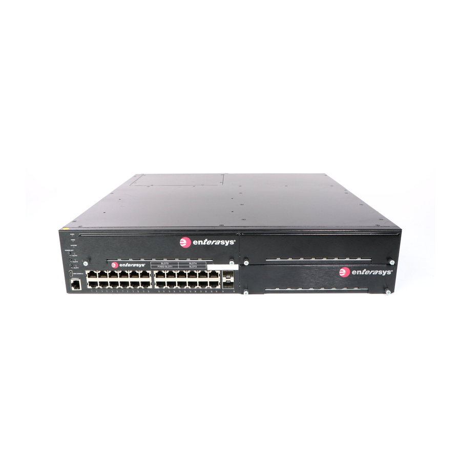
Gigabit XFP module. The G‐Series switch can be placed as a freestanding unit or installed into a standard 48.26‐ centimeter (19‐inch) rack. Figure 1-1 G3G124-24 Switch (front view) with one G3G-24TX IOM installed in Slot 2. SYSTEM LED Power Supply LEDs (PWR1 and PWR2) IOM power off buttons (Slots 2, 3 and 4) USB console port RJ45 console port... -
Page 20: Features
G3K‐2XFP, a 2‐port XFP module – G3K‐4XFP, a 4‐port XFP module Notes: Each combo SFP port on the G3G124-24, G3G124-24P or G3G-24TX supports the installation of Mini-GBICs for 1000Base-SX, 1000Base-LX, 100Base-FX or 1000Base-T copper SFP transceivers. Each combo SFP port in use on these 10/100/1000 base systems or the G3G-24TX module eliminates the availability of one RJ45 port. -
Page 21: Poe (Power Over Ethernet) Support
Power LEDs The two power LEDs indicate voltage for the primary and secondary power inputs. • Fans The G‐Series switch has nine fans in two different sizes located in three zones to serve different cooling functions. It supports fan redundancy, which means that the system will remain operational if one fan fails. Refer to “Fan Management” on page 1‐4 for more information. • System LED The SYSTEM LED indicates operational status of the system, as described in Table page 3‐2. • IOM power status LEDs IOM status LEDs indicate the operational status of optional module(s), including when they are powered down and can be safely removed, as described in “Removing an IOM” on page 2‐11. PoE (Power over Ethernet) Support The G3G124‐24P switch (and the G3G124‐24 switch and G3G‐24TX IOM equipped with a user‐ installed optional PoE card) are 802.3af compliant. This means they can provide Power over Ethernet cable connections from their RJ45 front panel connectors to powered devices (PDs) in the network. Power over Ethernet (PoE) refers to the ability to provide 48 Vdc power to a powered device using the same Ethernet cabling that provides data. Modern Ethernet implementations employ differential signals over twisted pair cables. This requires a minimum of two twisted pairs for a single physical link. Both ends of the cable are isolated with transformers blocking any DC or 3‐1 on Enterasys G-Series Hardware Installation Guide 1-3 Features... -
Page 22: Fan Management
• Devices such as PoE‐compliant remote EXIT signs and Personal Data Assistants (PDAs), • Devices that support Voice over IP such as PoE‐compliant digital telephones, • Devices that support Wireless Application Protocol (WAP) such as security cameras, laptop PCs, and many more devices. Fan Management The G3 system supports three groups of independently controllable fans and several firmware readable thermal sensors. Fan zones are as follows: • Group 1 (fans 1, 2, and 3) is located in the front left of the switch to cool the Ethernet subsystem and optional 1OM module slots. • Group 2 (fans 8 and 9) is located in the back left of the switch behind Group 1 to cool the CPU subsystem. • Group 3 (fans 4, 5, 6, and 7) is located on either side of the power slots to cool the power supplies Fan speeds are determined by thermal sensors located throughout the G3 system. The firmware samples the appropriate thermal sensors at regular intervals, and sets the appropriate fan speeds. Fan group 1 drives air flow across the front portion of the chassis, and fan groups 2 and 3 drive air flow across the rear portion of the chassis. For fan group 1, when all appropriate temperature sensors register temperatures of 50 degrees C or lower, group 1 fans run at 60% of maximum speed. If software detects any sensor reading (on the baseboard or any IOM module) above 50 degrees C, all group 1 fans will increase to 100% of maximum speed. In addition, if firmware detects a failure of any fan in group 1, all other group 1 fans will be increased to 100% of maximum speed. For fan group 2, behavior is similar. When all appropriate temperature sensors register temperatures of 50 degrees C or lower, group 1 fans run at 60% of maximum speed. If firmware detects any sensor reading (on the rear of the baseboard or any power supply sensor) above 50 degrees C, all group 2 and 3 fans will increase to 100% of maximum speed. In addition, if firmware detects a failure of any fan in group 2 or 3, all other group 2 and 3 fans will be increased to 100% of maximum speed. Refer to the Enterasys G‐Series Configuration Guide for information on using the G3 CLI to determine fan status. 1-4 Introduction... - Page 23 Installing and Removing a Power Supply Installing and Removing an IOM Connecting Power to the Switch Connecting to the Console Port Connecting to the Network Completing the Installation Installing an Optional PoE Module in the G3G124-24 Switch Installation Refer to page... 2-12 2-13 2-14...
-
Page 24: Unpacking The G-Series Switch
Note: G-Series 400-watt and 1200-watt power supply modules can be added to and combined on the same switch. Redundancy, however, will only be supported to the lowest common amount of power. For example, a 1200-watt module added to a switch with a 400-watt module would yield a 400-watt redundant solution. -
Page 25: Order Of Installation Steps
Removing power supplies. Removing and retaining screws securing the switch cover top and compact flash slot coverplate. Removing the switch cover. Refer to “Installing an Optional PoE Module in the G3G124‐24 Switch” on page 2‐21 for more information. Note: Instructions for installing PoE on the base switch do not apply to the G3G124-24P model since it is already equipped with a PoE card. Installing PoE capability in a G3G‐24TX IOM requires that you first uninstall the module, if necessary, and follow the procedure described in “Installing an Optional PoE Module on the G3G‐ 24TX” on page 2‐9. Mounting the Switch Perform one of the following to install the switch: •... -
Page 26: Placing The Switch On A Flat Surface
Note: The G-Series Ethernet switch (with rubber feet installed) will exceed the 2U high Richmond standard and will not comply with the requirements for mounting in a 19-inch (48.26-centimeter) rack. Remove the rubber feet, if installed, before installing the switch into a rack. -
Page 27: Installing And Removing A Power Supply
Figure 2-1 Attaching the Brackets to the Switch (G3G124-24 with G3G-24TX IOM shown) 1 Screws Using your mounting hardware, attach the front of the brackets to the rack. Tighten securely. Installing and Removing a Power Supply The following power supplies are available to be purchased from Enterasys for installation on the G‐Series switch. Follow the appropriate instructions in this section to install your component(s): • G3‐PWR, a 400‐watt AC power supply • G3‐PWR‐POE, a 1200‐watt AC power supply Power supplies can be mixed and can be used as redundant or non‐redundant. The switch will support a full 15.4 watts of power to 96 ports in non‐redundant power mode, and 9.4 watts of power to 96 ports in redundant power mode. By default, the G‐Series switch is set to operate in redundant mode. When two power supplies are installed, the power from each is evenly distributed. If one power supply fails, the second power supply assumes the load. The G3 switch automatically allots power to the base board and to each installed module. Each component’s power consumption is subtracted from the available power and the remaining power is equally distributed among installed PoE modules. A PoE module must be allotted a minimum of 37 watts to be operational. Refer to Appendix using the CLI to set the status of power redundancy and to review system power settings, refer to ... -
Page 28: Power Supply Planning
Installing and Removing a Power Supply Power Supply Planning As shown in Table switch setting) has not been disabled through the CLI, the power supplies share the load equally and provide power redundancy. If one power supply fails or is removed (hot swapped) for any reason, the other power supply takes up the load. Power redundancy remains in effect as long as the load does not exceed the power as stated in the Redundancy column. Table 2-1 Power Distribution According to Number of Installed Power Supplies Power Redundancy Supplies Yes, if power demand is less than the capacity of one power supply. -
Page 29: Installing A Power Supply
Precaución: Colocar de manera forzada una fuente de poder o no colocarla bien alineada podría dañarla y/o maltratar el panel posterior del chasis. With the power supply properly inserted into the opening, carefully slide the module until it connects to the backplane, as shown in Figure flush with the back of the G‐Series switch. If significant resistance is encountered before the power supply is seated, remove and reinsert it. Do not force the module into place. Installing and Removing a Power Supply 2‐2. The module’s handle should be nearly Enterasys G-Series Hardware Installation Guide 2-7... -
Page 30: Removing A Power Supply
Installing and Removing a Power Supply Figure 2-2 Installing a Power Supply Module (1200-watt module into PWR 2 slot shown) 1 Power supply Secure the power supply to the chassis by tightening the captive screws. If you are installing an additional power supply, repeat step 4 through step 7. If not, ensure that the unused power slot has a coverplate installed over it. Refer to “Power Supply Planning” on page 2‐6 for information on configuring the switch’s power mode. Removing a Power Supply To remove a power supply, proceed as follows: Attach an anti‐static wrist strap before handling the power supply module. Unplug the associated power cord from the outlet. Unplug the power cord from the AC inlet (associated with the power supply you are removing) at the back of the chassis. Unscrew the captive screws to release the power supply from the chassis. Remove the power supply by grasping the handle and pulling it straight out of the chassis. -
Page 31: Installing And Removing An Iom
IO. Installing an Optional PoE Module on the G3G-24TX Notes: Instructions in this section do not fully describe installing PoE on the G3G124-24 base system, which requires completing several disassembly steps first. For more information on base system assembly, refer to page 2-21. -
Page 32: Installing An Iom
PoE daughter card module IOM to PoE connector Using the screws shipped with the PoE module, firmly attach the PoE module to the IOM. Installing an IOM If you have one or more IOMs that you wish to install into the switch, you should do so before you connect power to the switch. Be aware that any IOM module inserted into a running switch will not be recognized until the switch is rebooted. Note: IOM modules can be hot-inserted into the G-Series switch, but must be removed by following the procedure described in To install an IOM module, refer to Figure Attach an ESD wrist strap to your wrist. Unpack the module by taking it from its shipping box and removing any packaging materials, and removing the module from its protective plastic bag. (Save the shipping box and materials in the event the unit must be reshipped.) Examine the module carefully, checking for damage. If any damage is found, do not install it. ... -
Page 33: Removing An Iom
LEDs will display as described in Removing an IOM Caution: Do not attempt to remove an IOM module from the G-Series switch when power is on to the switch without performing the following procedure. Precaución: No intente retirar el módulo IOM del switch G Series si éste está encendido. Antes de hacerlo, debe realizar el siguiente procedimiento. -
Page 34: Power Led Displays
Connecting Power to the Switch Caution: Use caution when removing an IOM on which you have optional PoE installed to avoid damaging the PoE module. Precaución: Tenga cuidado al retirar un IOM que tenga un módulo PoE instalado, ya que éste puede dañarse. -
Page 35: Connecting To The Console Port
Refer to the Enterasys G‐Series CLI Reference for information on how to specify whether two installed power supplies will operate in additive or redundant mode. Connecting to the Console Port Note: Only one console port on the G-Series switch can be active at any given time, either the RJ45 or the USB port. Connecting to the RJ45 Console Port The RS‐232 console port uses a standard 8‐pin RJ45 connector. An RJ45 to DB9 adapter is provided with the switch, but you must provide your own RJ45 to RJ45 straight‐through console cable. Refer to Table 2‐2 for console port pinout assignments. ... -
Page 36: Connecting To The Usb Console Port
Receive (RX) Transmit (TX) Ground (GRD) For a description of how to use the CLI and descriptions of all the CLI commands, refer to the Enterasys G‐Series CLI Reference . Connecting to the USB Console Port Note: Before connecting a PC into the G-Series USB console port, you must download to the PC and install a third party driver located at http://www.silabs.com/tgwWebApp/public/web_content/products/Microcontrollers/USB/en/ mcu_vcp.htm. -
Page 37: Connecting A Utp Cable Segment To Rj45 Port
Connecting a UTP Cable Segment to RJ45 Port Verify that a link exists by checking that the Link/Activity LED is on (solid green or blinking green). If the Link/Activity LED is off, perform the following steps until it is on: Verify that the cabling being used is Category 5 or better with an impedance between 85 and 111 ohms with a maximum length of 100 meters (328 feet). b. Verify that the device at the other end of the twisted pair segment is on and properly connected to the segment. Verify that the RJ45 connectors on the twisted pair segment have the proper pinouts and check the cable for continuity. Typically, a crossover cable is used between hub devices. A straight‐through cable is used to connect between G‐Serieses or hub devices and an end user (computer). Refer to Figure 2‐6 and Figure to Figure 2‐8 and Figure d. Ensure that the twisted pair connection meets the dB loss and cable specifications outlined in the Cabling Guide. Refer to “Related Documents” on page xvi for information on obtaining this document. If a link is not established, contact Enterasys Networks. Refer to “Getting Help” on page xviii for details. Repeat all steps above until all connections have been made. 2‐5 and proceed as follows: 2‐7 for four‐wire RJ45 connections. Refer 2‐9 for eight‐wire RJ45 connections. Enterasys G-Series Hardware Installation Guide 2-15 Connecting to the Network... -
Page 38: Four-Wire Crossover Cable Rj45 Pinouts For 10/100Base-Tx
Connecting to the Network Figure 2-6 Four-Wire Crossover Cable RJ45 Pinouts for 10/100BASE-TX Ã 1 RJ45 switch port 2 Other device port Figure 2-7 Four-Wire Straight-Through Cable RJ45 Pinouts for 10/100BASE-TX Ã 1 RJ45 switch port 2 Other device port... -
Page 39: Installing Optional Sfp/Xfp
Installing Optional SFP/XFP Notes: Each combo SFP port in use on the G3G124-24 or G3G124-24P base systems or the G3G- 24TX module eliminates the availability of one RJ45 port. In other words, only 24 ports can be active at any given time on components equipped with a combination of RJ45 and SFP interfaces. -
Page 40: Installing An Sfp/Xfp (Shown With Lc Connector And Without Dust Cover)
Connecting to the Network Caution: Carefully follow the instructions in this manual to avoid damaging the SFP/XFP and G-Series. The SFP/XFP and G-Series are sensitive to static discharges. Use an antistatic wrist strap and observe all static precautions during this procedure. Failure to do so could result in damage to the SFP/XFP and G-Series. -
Page 41: Removing An Xfp/Sfp
Si nota que losextremos de los cables de fibra óptica se ensucian, utilice aire comprimido paralimpiarlos. También puede limpiarlos con un estropajo embebido en alcohol isopropílico. Refer to Figure 2‐11 as you perform the following procedure. To connect an LC or MT‐RJ cable connector to an SFP or XFP port connector: Remove the protective covers (not shown) from the uplink port SFP/XFP and from the connectors on each end of the cable. port slot, refer back to Figure 2‐10 and proceed as follows: Enterasys G-Series Hardware Installation Guide 2-19 Connecting to the Network... -
Page 42: Completing The Installation
Cable Connection (LC shown) to Uplink Port with SFP/XFP Installed Combo SFP port with MGBIC installed Plug the other end of the cable into the appropriate port on the other device. Some cables may be terminated at the other end with two separate connectors, one for each fiber‐optic strand. In this case, ensure that the transmit fiber‐optic strand from the G‐Series is connected to the receive port of the other device, and the receive fiber‐optic strand on the G‐Series is connected to the transmit port of the other device. Repeat this procedure for other SFP/XFP ports, if needed. If an SFP/XFP port is unused, install a dust cover. Completing the Installation Power on the switch. Verify that the PWR1 and PWR2 power LEDs are lit. Refer to “Power LED Displays” on page 2‐12 for information on interpreting the power LEDs. Verify that the SYSTEM LED blinks initially then becomes solid green. Make sure that the network devices connected to the switch ports are powered on, then verify that each Link/Activity LED is ON (solid green or blinking green). At the device connected to the console port, perform the following: Enter admin for Username. b. At the Password prompt, press ENTER (RETURN). 2-20 Installation connector until it clicks into place. -
Page 43: Installing An Optional Poe Module In The G3G124-24 Switch
If you have purchased an optional PoE module (G3G‐POE), have unplugged all network and power connections and removed power supplies, you must remove the switch cover as follows to access the PoE board connectors in the G‐Series base chassis. Caution: Be sure to retain all screws removed from the G-Series switch cover in a secure location to avoid misplacing them. Leaving any loose screws inside the switch could result in severe damage to switch components. Precaución: Asegúrese de colocar todos los tornillos que haya retirado de la cubierta del switch G- Series en un lugar seguro, para evitar perderlos. -
Page 44: Installing The Poe Module
Installing an Optional PoE Module in the G3G124-24 Switch Figure 2-12 Screw and Coverplate Removal for Removing the G3G124-24 Cover Using a Phillips screwdriver and a counter‐clockwise motion, remove all necessary screws. Retain screws and the Compact Flash coverplate in a secure location until the PoE module installation is complete and you are ready to reinstall the switch cover. Lift the cover off the switch. Installing the PoE Module Once you have completed the steps described in “Removing the Switch Cover” on page 2‐21, you can install the PoE module in the base switch. Installation instructions and the location of standoffs and PoE‐to‐motherboard connections (behind the ports) are the same as previously described for installing PoE on the G3G‐24TX IOM. To install an optional PoE module in the G‐Series base switch: Using Figure in “Installing an Optional PoE Module on the G3G‐24TX” on page 2‐9. Replace the switch cover and Compact Flash coverplate and secure all screws. Reinstall all necessary components in the switch. 2-22 Installation... -
Page 45: Chapter 3: Troubleshooting
Elektrischer Gefahrenhinweis: Das Gerät kann Strom aus zwei Stromquellen beziehen. Stellen Sie sicher, dass die Stromzufuhr von beiden Stromquellen unterbrochen ist, bevor Sie Reparaturen vornehmen oder Verbindungen entfernen. Troubleshooting Refer to page... Enterasys G-Series Hardware Installation Guide 3-1... -
Page 46: Checking The Leds
Checking the LEDs Checking the LEDs The following sections define the behavior of the LEDs on the G‐Series Ethernet switch chassis and on the IOMs. Refer to Figure Figure 3-1 G3 system LEDs (G3G124-24 shown) Power Supply LEDs (PWR1 and PWR2) System LED SYSTEM LED The SYSTEM LED indicates the state of the system, as described in Table Table 3-1 SYSTEM LED Definitions Display Solid red Blinking red Solid amber Blinking amber... -
Page 47: Power Leds
For RJ45 ports, this indicates power up. Blinking Amber Link established with activity and failure to provide power to powered devices. RJ45 only) Checking the LEDs 3‐3. “Removing an IOM” on page 2-11 for correct Enterasys G-Series Hardware Installation Guide 3-3... -
Page 48: Using The Reset Button
Note: Notify the system manager before changing the password. To reset the G‐Series password: Locate the reset button on the back of the switch as shown in Figure Figure 3-2 Locating the Reset button Reset button Press‐and‐hold the reset button while the switch is operational. This changes the login password to the default password and will be indicated by means of the command line interface (CLI) only. You can now logon to the switch using the default password via the Console port and assign a new password using the CLI. To access switch management from your local PC, terminal, or modem connection, refer to the Enterasys G‐Series Configuration Guide for instructions on how to log in and enter a new password. If you require assistance, contact Enterasys Networks using one of the methods described in “Getting Help” on page xv. Removing the Switch from a Rack To remove the G‐Series Ethernet switch from a rack: While supporting the switch so it does not fall, carefully remove the mounting screws from the two brackets that attach the switch to the rack. If necessary, remove each bracket from the switch by removing the mounting kit screws as shown in Figure 3-4 Troubleshooting 2‐1 on page 2‐5. -
Page 49: Appendix A: Specifications
RJ45 connectors. These ports also support 802.3af PoE connections on the G3G124-24P base unit (or when the optional PoE module is installed on the G3G124-24 base unit). Two ports that support optional Mini-GBICs 100BASE-FX, 1000BASE- LX/SX fiber-optic connections and 1000BASE-T copper connections. - Page 50 • G3G170-24 - 134,153 hrs Same as Power Consumption (below) 100 to 240 VAC • G3G124-24 - 126 W (429 BTU/hr) • G3G124-24P - 130 W (443 BTU/hr) without PoE power draw • G3G170-24 - 92.18W (214 BTU/hr) 50 to 60 Hz •...
-
Page 51: Iom Module Specifications
RJ45 connectors. These ports also support 802.3af PoE connections on the G3G124-24P base unit (or when the optional PoE module is installed on the G3G124-24 base unit). Two ports that support optional Mini-GBIC 100BASE-FX, 1000BASE- LX/SX fiber-optic connections and 1000BASE-T copper connections. -
Page 52: G3K-2Tx And G3K-4Tx Iom Specifications
IOM Module Specifications Table A-3 G3G-24SFP IOM Specifications (continued) Item Predicted hours for Mean Time Between Failures (MTBF) Heat Dissipation (maximum) Power Specifications Input Voltage Power Consumption Input Current Thermal Output Environmental Operating Temperature Storage Temperature Operating Relative Humidity Table A-4 G3K-2TX and G3K-4TX IOM Specifications Item G3K-2TX and G3K-4TX G3K-2TX... -
Page 53: Torque Values
LC duplex style connector. 1 LC fiber-optic multimode port that is compliant with the 100BASE-FX standard and has an LC connector. Torque Values Bit Size Nominal 1.57 3.15 5.25 9.45 18.0 18.90 32.0 33.60 67.0 70.35 Enterasys G-Series Hardware Installation Guide A-5... -
Page 54: Mgbic-Lc01/Mgbic-Mt01 Specifications (1000Base-Sx
1-Gigabit Ethernet and 100Base-FX Transceiver (SFP) Specifications Table A-6 Mini-GBIC Input/Output Port Specifications (continued) Item MGBIC-LC05 MGBIC-LC07 MGBIC-08 MGBIC-LC09 The specifications for the Mini‐GBICs shown in Table A‐7 through Table IEEE 802.3z‐1998 standard. MGBIC-LC01/MGBIC-MT01 Specifications (1000BASE-SX) Table A-7 MGBIC-LC01/MGBIC-MT01 Optical Specifications Item Transmit Power (minimum) Receive Sensitivity Link Power Budget Table A-8 MGBIC-LC01/MGBIC-MT01 Operating Range Item 62.5 µm MMF 62.5 µm MMF... -
Page 55: Mgbic-Lc03 Specifications (1000Base-Sx
Modal Bandwidth @ 1310 nm 160 MHz/km 400 MHz/km 62.5 µm MMF -20 dBm -31 dBm 11 dBm 1310 nm Enterasys G-Series Hardware Installation Guide A-7 50/125 µm MMF -9.5 dBm -3 dBm -20 dBm 10.5 dB Range 2,000 Meters 2,000 Meters 50 µm MMF... -
Page 56: Mgbic-Lc05 Specifications (100Base-Fx
1-Gigabit Ethernet and 100Base-FX Transceiver (SFP) Specifications MGBIC-LC05 Specifications (100BASE-FX) Table A-14 MGBIC-LC05 Optical Specifications Item Transmit Power (minimum) Receive Sensitivity Link Power Budget 1. The maximum drive distance (up to 10 km) depends on the quality of the installed single-mode fiber-optic cable segment. -
Page 57: Mgbic-08 Specifications (1000Base-Elx
28 dB, typical Range 80,000 Meters 50 µm MMF 10 µm SMF -11.5 dBm -9.5 dBm -20 dBm -20 dBm 8.5 dBm 10.5 dBm Range 2-550 Meters 2-550 Meters 2-550 Meters 2-10,000 Meters Enterasys G-Series Hardware Installation Guide A-9 A‐22 ... -
Page 58: Console Port Pinout Assignments
Console Port Pinout Assignments Table A-22 XFP Fiber-Optic Specifications Module 10GBASE-LR-XFP 10GBASE-ER-XFP 10GBASE-ZR-XFP 10GBASE-SR-XFP The specifications listed in Table Table A-23 Recommended Cable Types and Specifications Item 10GBASE-LR-XFP 10GBASE-ER-XFP 10GBASE-ZR-XFP 10GBASE-SR-XFP 1. The limiting factor is saturation of the receiver by the transmitter. When presented with a signal at a strength above the saturation point, the receiver cannot distinguish between pulses, though no hardware damage occurs. - Page 59 Powered device classifications Rack mounting Recommended A-10 Regulatory compliance A-10 Removing the switch from a rack Reset button Safety requirements A-10 SFP/XFP connecting cables to ports 2-19 installing optional 2-17 Specifications 100Base-FXTransceiver (XFP)