Viessmann Vitosol-F Installation Instructions For Contractors
Flat-plate collector for installation on collector supports collector supports with fixed angle of inclination
Hide thumbs
Also See for Vitosol-F:
- Installation instructions manual (80 pages) ,
- Installation instructions for contractors (24 pages) ,
- Service instructions manual (24 pages)

Related Manuals for Viessmann Vitosol-F


Summary of Contents for Viessmann Vitosol-F
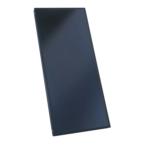
- Page 1 VIESMANN Installation instructions for contractors Vitosol-F/-FM Type SV and SH Flat-plate collector for installation on collector supports Collector supports with fixed angle of inclination VITOSOL-F/-FM Dispose after installation. 5698352 GB/en 9/2017...
- Page 2 Safety instructions Please follow these safety instructions closely to prevent accidents and material losses. Safety instructions explained Please note Note This symbol warns against the risk of material Details identified by the word "Note" contain additional losses and environmental pollution. information.
-
Page 3: Table Of Contents
Index Information Disposal of packaging ................Symbols ....................Intended use ..................Product information ................Collector support standard set and collector support extension ..■ Retaining rail for 1 collector ............■ Retaining rail for 2 collectors ............■ Cross brace ..................■... - Page 4 Disposal of packaging Disposal of packaging DE: Use the disposal system organised by Viessmann. Please dispose of packaging waste in line with statu- AT: Use the ARA statutory disposal system (Altstoff tory regulations. Recycling Austria AG, licence number 5766). CH: Packaging waste is disposed of by the HVAC contractor.
- Page 5 Intended use (cont.) Any usage beyond this must be approved by the man- Incorrect usage also applies if components in the sys- ufacturer in each individual case. tem are modified from their intended use (e.g. through direct DHW heating in the collector). Incorrect usage of the collectors or the installation sys- tem or incorrect operation is prohibited (e.g.
- Page 6 Product information (cont.) Retaining rail for 1 collector Fig. 2 Retaining rail for 2 collectors Fig. 3 Cross brace Fig. 4 Washer 8.4 mm Cross brace Hexagon nut M 8 Hexagon bolt M 8 x 20...
- Page 7 Product information (cont.) Installation aid template To prevent slipping of collectors during installation (accessories). Fig. 5 Template Hinged clip The following tables contain the number of required component assemblies subject to the number of col- lectors to be installed. Type SV Number of col- Number of component assemblies lectors...
-
Page 8: Calculating Collector Row Clearance Z
Calculating collector row clearance z When installing several collectors one behind the other, maintain clearance z to prevent unwanted shad- ing. α α β Fig. 6 z Collector row clearance Collector angle of inclination α Angle of the sun β Collector angle of inclination Collector row clearance z in mm α... - Page 9 Fitting collector supports (cont.) Fig. 7 Use retaining rails as spacers between the collector supports. Type Number of col- y in mm lectors x in mm 2580 1000 Type SV Type SH 1080 2400 2155 4805 3235 7205 4310 9610 5390 12010 6470...
-
Page 10: Fitting Cross Braces
Fitting cross braces To stabilise the collector array, secure cross braces diagonally to the collector supports using screws at the back (see diagram below). To install the cross braces, holes in the collector sup- ports and the cross braces must be drilled on site. Fig. - Page 11 Installing the collectors (cont.) Installation information Use the template as an aid for installing the second ■ The side with the type plate must be on the outside collector and all others between the supports. Once of the first and last collector (see label). the second collector has been secured, remove the On just one of the collectors, fit the pipework at the template and install it between the next pair of sup-...
-
Page 12: Connecting The Collectors
Installing the collectors (cont.) Fig. 12 Repeat steps 4 to 6 according to the number of collectors. Connection pipe Type plate 5. Do not tighten the clamping brackets between 2 collectors until the next collector has been connec- ted to the previous one. Connecting the collectors The connection and sensor well sets are packed sepa- rately. - Page 13 Connecting the collectors (cont.) Sensor well set Fig. 14 Note The collector temperature sensor is part of the stand- ard delivery of the solar control unit. Installation information Lubricate O-ring seals only with the special valve ■ grease provided. Initially tighten the union nut by hand, then tighten ■...
-
Page 14: Covering The Collector
Soft solder could be weakened, particularly near the collectors, due to the high temperatures that occur there. Metal seal connections, locking ring fittings or Viessmann plug-in connections with double O-rings are the most suitable. If other seals such as flat gaskets are used, ade- quate glycol, pressure and temperature stability must be guaranteed by the manufacturer. - Page 15 Installation (cont.) Fig. 16 Solar-Divicon Fill valve Shut-off valves Stagnation heat sink Non-return valves Expansion vessel Solar circuit pump Drip pan Air separator Collector Shut-off valve (adjusting screw above flow indica- DHW cylinder Cylinder temperature sensor Drain valve Collector temperature sensor Flow indicator Solar control unit...
- Page 16 Commissioning "Vitosol-F/-FM" service instructions Viessmann Werke GmbH & Co. KG Viessmann Limited D-35107 Allendorf Hortonwood 30, Telford Telephone: +49 6452 70-0 Shropshire, TF1 7YP, GB Fax: +49 6452 70-2780 Telephone: +44 1952 675000 www.viessmann.com Fax: +44 1952 675040 E-mail: info-uk@viessmann.com...