IBM BladeCenter S Problem Determination And Service Manual
Hide thumbs
Also See for BladeCenter S:
- Installation and user manual (84 pages) ,
- Planning manual (130 pages) ,
- Product manual (40 pages)
Table of Contents
Advertisement
Quick Links
Advertisement
Table of Contents
Troubleshooting

Related Manuals for IBM BladeCenter S


Summary of Contents for IBM BladeCenter S
- Page 1 IBM BladeCenter S Type 7779/8886 Problem Determination and Service Guide...
- Page 3 IBM BladeCenter S Type 7779/8886 Problem Determination and Service Guide...
- Page 4 Note Note: Before using this information and the product it supports, read the general information in Notices; and read the IBM Safety Information and the IBM Systems Environmental Notices and User Guide on the IBM Documentation CD. The most recent version of this document is available at http://www-947.ibm.com/systems/support/.
-
Page 5: Table Of Contents
. 88 Components of the BladeCenter S system. Removing a blade server . . 89 Front view of the BladeCenter S chassis . Installing a blade server . . 90 Rear view of the BladeCenter S chassis . . 12 Removing a fan module . - Page 6 . 124 Index ....127 Japan Electronics and Information Technology Industries Association (JEITA) statement . . 125 BladeCenter S Type 7779/8886: Problem Determination and Service Guide...
-
Page 7: Safety
Ennen kuin asennat tämän tuotteen, lue turvaohjeet kohdasta Safety Information. Avant d'installer ce produit, lisez les consignes de sécurité. Vor der Installation dieses Produkts die Sicherheitshinweise lesen. Prima di installare questo prodotto, leggere le Informazioni sulla Sicurezza. © Copyright IBM Corp. 2007, 2012... -
Page 8: Guidelines For Servicing Electrical Equipment
If you have to work on equipment that has exposed electrical circuits, observe the following precautions: – Make sure that another person who is familiar with the power-off controls is near you and is available to turn off the power if necessary. BladeCenter S Type 7779/8886: Problem Determination and Service Guide... -
Page 9: Inspecting For Unsafe Conditions
Make sure that the insulation is not frayed or worn. 4. Remove the cover. 5. Check for any obvious non-IBM alterations. Use good judgment as to the safety of any non-IBM alterations. 6. Check inside the computer for any obvious unsafe conditions, such as metal filings, contamination, water or other liquid, or signs of fire or smoke damage. -
Page 10: Safety Statements
Be sure to read all caution and danger statements in this documentation before you perform the procedures. Read any additional safety information that comes with your BladeCenter S system or optional device before you install the device. Statement 1 viii... - Page 11 Statement 2 CAUTION: When replacing the lithium battery, use only IBM Part Number 33F8354 or an equivalent type battery recommended by the manufacturer. If your system has a module containing a lithium battery, replace it only with the same module type made by the same manufacturer.
- Page 12 Class 1 Laser Product Laser Klasse 1 Laser Klass 1 Luokan 1 Laserlaite Appareil A Laser de Classe 1 Statement 8 BladeCenter S Type 7779/8886: Problem Determination and Service Guide...
- Page 13 CAUTION: Never remove the cover on a power supply or any part that has the following label attached. Hazardous voltage, current, and energy levels are present inside any component that has this label attached. There are no serviceable parts inside these components.
- Page 14 Always install stabilizer brackets on the rack cabinet. v Always install servers and optional devices starting from the bottom of the rack cabinet. v Always install the heaviest devices in the bottom of the rack cabinet. BladeCenter S Type 7779/8886: Problem Determination and Service Guide...
-
Page 15: Chapter 1. Introduction
IBM Predictive Failure Analysis (PFA) and real-time diagnostics. v Server expansion capabilities You can add up to six blade servers to the BladeCenter S chassis. Some blade servers have connectors for additional optional devices that you can use to add capabilities to the blade server. -
Page 16: Related Documentation
The advanced management module is used to communicate with the service processor in each blade server to provide system monitoring, event recording, and alerts. You can manage the BladeCenter S chassis, its devices, and the blade servers remotely. Related documentation... -
Page 17: The Ibm Bladecenter Documentation Cd
Additional documentation might be included on the IBM BladeCenter Documentation The BladeCenter S chassis might have features that are not described in the documentation that comes with the BladeCenter S chassis. The documentation might be updated occasionally to include information about those features, or technical updates might be available to provide additional information that is not included in the BladeCenter documentation. -
Page 18: Notices And Statements In This Document
/mnt/cdrom directory: sh runlinux.sh Select your BladeCenter S chassis from the Product menu. The Available Topics list displays all the documents for your BladeCenter product. Some documents might be in folders. A plus sign (+) indicates each folder or document that has additional topics under it. -
Page 19: Features And Specifications
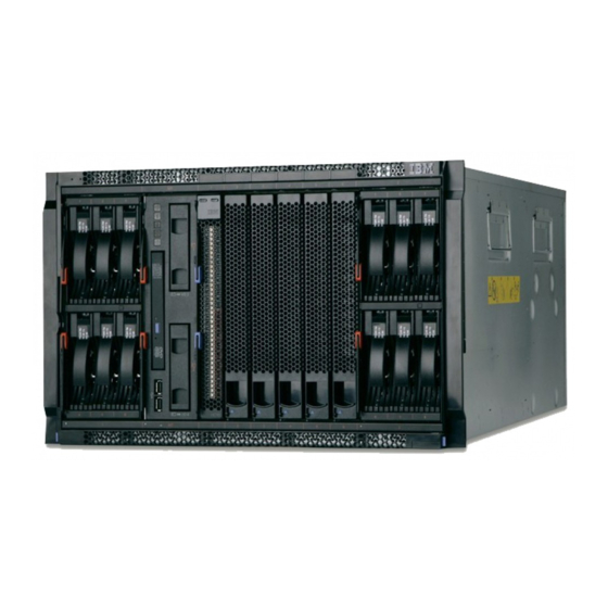
One hot-swap advanced management module Components of the BladeCenter S system BladeCenter S system components include an advanced management module, blade servers, I/O modules, storage modules, power modules, fan modules, a serial pass-thru module, and a media tray. Chapter 1. Introduction... -
Page 20: Front View Of The Bladecenter S Chassis
Blade servers, storage modules, and the media tray are installed in the front of the BladeCenter S chassis. Note: For proper cooling, each bay in the BladeCenter S chassis must have either a device or a filler installed. The following illustration shows the front of the BladeCenter S chassis. - Page 21 Note: Four power modules are required in the BladeCenter S chassis if both storage modules are installed. To access the hard disk drives in the storage module, the following devices must be installed: v SAS I/O modules. You can choose to install either SAS connectivity modules or SAS RAID controller modules.
- Page 22 Note: When power is restored to the BladeCenter S chassis after a complete loss of power and you have implemented the hard disk drives as a mirrored array, the fault light will blink as the hard disk drive is being resynchronized.
- Page 23 System LED panel The LEDs on this panel provide status information for the BladeCenter S chassis. Note: These LEDs are also displayed on the rear of the BladeCenter S chassis. Power-on Lit (green). Power is being supplied to the BladeCenter S chassis.
- Page 24 Charging Lit (green). The battery backup unit is being charged. Fault Lit (amber). The battery backup unit has a failure. If the Fault LED is lit, replace the battery backup unit. BladeCenter S Type 7779/8886: Problem Determination and Service Guide...
- Page 25 Power-control button Power-on LED You can find the documentation for blade servers in the IBM Systems Information Center, which is at http://publib.boulder.ibm.com/infocenter/systems/index.jsp. To access the blade server documentation from this site, click Systems hardware > BladeCenter information > Blade servers.
-
Page 26: Rear View Of The Bladecenter S Chassis
Fan modules, I/O modules, power modules, the advanced management module, and the serial pass-thru module are in the rear of the BladeCenter S chassis. Note: Each bay in the BladeCenter S chassis must have either a device or a filler installed. - Page 27 BMC) in each blade server to support features such as blade server power-on requests, error and event reporting, KVM requests, and requests to use the BladeCenter S chassis shared media tray. Chapter 1. Introduction...
- Page 28 Port activity LED address Release handle The BladeCenter S chassis supports a single advanced management module, and it must be installed in the advanced management module bay. Advanced management module indicators and controls: The advanced management module has several LEDs that you can use to obtain status about the advanced management module and the Ethernet connection.
- Page 29 Therefore, you should always make sure that you save your current configuration before resetting the advanced management module. For more information about saving and restoring configurations, see the IBM BladeCenter Advanced Management Module User's Guide. Advanced management module input and output connectors:...
- Page 30 The serial pass-thru module has six serial ports that you can use to directly attach a four-wire serial RJ-45 connector to each of the blade servers in the BladeCenter S chassis. If you use the serial pass-thru module, it must be installed in the serial pass-thru module bay.
- Page 31 Serial pass-thru module Release handle Serial pass-thru connector pinout There are eight pins on each RJ-45 port, numbered 1 through 8, from bottom to top. Serial pass-thru module Release handle Contact (pin number) Signal name Signal direction RTS (Request to Output from blade server send) Not used...
- Page 32 Note: The serial pass-thru module uses the DTE convention. I/O modules You can install up to four I/O modules in the BladeCenter S chassis, including Ethernet switch modules, Fibre Channel switch modules, pass-thru modules (optical and copper), SAS connectivity modules, and SAS RAID controller modules.
- Page 33 (either SAS connectivity modules, SAS RAID controller modules, Ethernet switch modules, pass-thru modules, or Fibre Channel switch modules). Power modules The BladeCenter S system supports up to four autoranging power modules that are capable of supporting either 110 V ac or 220 V ac. Fault LED...
- Page 34 1 and 2 (the top and bottom power module bays on the right as you face the rear of the BladeCenter S chassis). Note: You must install all four power modules if you are using both storage modules.
-
Page 35: Systems And Storage Management
Note: If one of the fans in the fan module fails, the other fan will begin operating at full speed. Systems and storage management IBM provides products that you can use to manage your BladeCenter S system and the integrated shared storage that is available. IBM Director IBM Director provides a comprehensive entry-level workgroup hardware manager. -
Page 36: Storage Configuration Manager
Inventory your environment v Perform updates to managed systems, such as device drivers and firmware v Automatically perform an action based on events or schedules, if IBM Director is configured to do so By deploying IBM Director, you can achieve reductions in ownership costs through... -
Page 37: Connecting To Your Bladecenter S Types 7779 And 8886
Note: After you disconnect the BladeCenter S chassis from power, wait at least 5 seconds before you connect the BladeCenter S chassis to power again. Connecting to your BladeCenter S Types 7779 and 8886 To perform the initial configuration, you will typically connect to the advanced management module through the Ethernet port on the advanced management module. - Page 38 PASSW0RD) v Command-line interface. From a console window, access the advanced management module IP address or host name using Telnet or SSH. Then, log in using the user ID and password. BladeCenter S Type 7779/8886: Problem Determination and Service Guide...
-
Page 39: Chapter 2. Diagnostics
If the front or rear system error LED of the BladeCenter S chassis is lit, one or more error LEDs on a component also might be lit. These LEDs help identify the cause of the problem. - Page 40 From the advanced management module Web interface, click the name of the blade server in the Blade LEDs section of the LEDs link. 5. Contact IBM support. BladeCenter S Type 7779/8886: Problem Determination and Service Guide...
- Page 41 Note: To find descriptions and actions for LEDs on I/O modules or blade servers, see the documentation that comes with the device. You can find the documentation for I/O modules and blade servers at the IBM Systems Information Center, which is at http://publib.boulder.ibm.com/ infocenter/systems/index.jsp.
- Page 42 Note: Before unplugging the AC power cord from the module has failed. power module or removing the power module from the BladeCenter S chassis, verify that the capacity of the remaining power modules are sufficient to meet the minimum power requirements for all components in the BladeCenter S chassis.
-
Page 43: Event Log
Event log The advanced management module event log contains messages that are generated while the advanced management module is monitoring the BladeCenter S system. Messages in the event log have the following format: v Severity error level. The severity level can be information (I), warning (W), or error (E). - Page 44 Controller or BMC) that operates independently of the CPUs on the blade server. It runs whenever the blade server is installed in the BladeCenter S system and connected to active power supplies; the blade server does not need to be powered The service processor communicates with the advanced management module to provide vital product data (VPD) and health status about the blade server.
- Page 45 BLADE_07 08/24/06, 17:38:25 (id14c2n07) Memory disabled: DIMM number 2 BLADE_07 08/24/06, 17:38:25 (id14c2n07) Memory disabled: DIMM number 1 I2C errors Error messages related to the BladeCenter S system hardware components and communications between the components (known as I2C errors) are displayed in the advanced management module event log.
- Page 46 3. Wait five minutes to allow the advanced management module to reset the I2C bus. If an I2C bus error recovery message does not appear in the event log after five minutes, contact IBM support. BladeCenter S Type 7779/8886: Problem Determination and Service Guide...
-
Page 47: Chapter 3. Troubleshooting
This chapter explains how to troubleshooting and resolve any problems that you may have with the BladeCenter S Types 7779 and 8886. Updating firmware Several components in the BladeCenter S chassis contain firmware that you can update. Before you begin... -
Page 48: Service Bulletins
Service bulletins IBM continually updates the support Web site with tips and techniques that you can use to resolve any problems that you may be having with the BladeCenter S system. To find any service bulletins that are available for the BladeCenter S Types 7779 and 8886, go to the BladeCenter support search Web site at http://www.ibm.com/... - Page 49 Power Management page. If so, remove power supply 1. 8. If you still do not have a minimum configuration that works, contact IBM Support. 9. Bring up a blade server by reengaging the blade server and starting it. Choose a blade server that does not require the storage modules to boot.
-
Page 50: Troubleshooting Symptoms By Component
Use this information to resolve problems with the management module. The advanced management module is the central point of management for the BladeCenter S system. If it is not present and functioning, you will not be able to perform normal management functions for the devices in the BladeCenter S system. - Page 51 3. If possible, verify whether the advanced management module is running the network servers on their default network ports. If you cannot log in at all, check with the administrator for the BladeCenter S system. If you are connected through the serial port, use the ports command to ensure that all interfaces are enabled and the TCP ports are correct.
- Page 52 Install the advanced management module. The fans will return to their normal level (in speed and noise) after the advanced management module has completed its POST process. BladeCenter S Type 7779/8886: Problem Determination and Service Guide...
- Page 53 For more information about restoring a previously saved configuration, see the IBM BladeCenter Advanced Management Module User's Guide. a) Insert a paper clip into the pin hole on the back of the advanced management module.
-
Page 54: Troubleshooting Blade Server Problems
IP address 192.68.70.100 and subnet mask 255.255.255.0 so that it does not conflict with any default IP address in the BladeCenter S system. 5. Attempt to log in using the default user ID and password. The default user ID is USERID and the default password is PASSW0RD (with a zero in place of the letter O). - Page 55 IBM continually updates the support Web site with tips and techniques that you can use to resolve any problems that you may be having with the BladeCenter S system. Go to the BladeCenter support search Web site at http://www.ibm.com/ systems/support/supportsite.wss/search?brandind=5000020 to see if any service...
- Page 56 3. Verify that there is sufficient power availability configured to power on the blade server. Click Power Management and then click Power Domain to find the domain policy in place for the BladeCenter S system. You can configure one of the following policies: v AC power source redundancy With this policy, the total allowable power draw is limited to the capacity of two power modules.
- Page 57 If a single power module fails, all the blade servers that are powered on will continue to operate at normal performance levels. If two or more power modules fail, the BladeCenter S chassis could power off.
- Page 58 Perform these steps to resolve the problem: 1. For the I-error message, look at the message text: BLADE_07 08/24/06, 17:38:25 (id14c2n07) Memory disabled: DIMM number 2 BLADE_07 08/24/06, 17:38:25 (id14c2n07) Memory disabled: DIMM number 1 BladeCenter S Type 7779/8886: Problem Determination and Service Guide...
- Page 59 In addition to the kernel mode error, the event log will typically display service processor communication errors for multiple blade servers in the BladeCenter S chassis. Problem The advanced management module Web interface displays kernel mode on the VPD panel for a blade server.
- Page 60 3. Swap the blade server with a working blade server of the same type. If the problem persists with the blade server in the new location, contact IBM support for possible replacement. 4. If the LEDs on the replacement blade server are not lit, the problem may be in the blade server bay.
- Page 61 No VPD available from advanced management module Vital Product Data (VPD) for each blade server in the BladeCenter S chassis is available from the advanced management module interface. Use this procedure to troubleshooting the situation where VPD does not appear.
- Page 62 These errors are typically caused by problems in firmware or configuration (either on the advanced management module or on the blade server). Problem You installed a new blade server in the BladeCenter S chassis, and the advanced management module log is displaying service processor communication errors. Investigation Perform these steps to resolve the problem: 1.
- Page 63 Watchdog timeout messages displayed for a blade server Watchdog timeout messages are displayed in the advanced management module event log. Use this procedure if there are multiple blade servers in a BladeCenter S chassis and you are seeing these messages for only one of the blade servers.
- Page 64 – If the blade server is still nonresponsive, force the blade server to boot from the backup flash image. You will need to remove the blade server from the BladeCenter S chassis, open the cover, and move one of the jumpers. See the documentation that came with the blade server for information about this procedure.
-
Page 65: Troubleshooting Fan Module Problems
Use this information to resolve problems with a fan module. IBM continually updates the support Web site with tips and techniques that you can use to resolve any problems that you may be having with the BladeCenter S system. Go to the BladeCenter support search Web site at http://www.ibm.com/ systems/support/supportsite.wss/search?brandind=5000020 to see if any service... - Page 66 IBM support. Fan modules continually cycle to full speed If fan modules continually cycle between normal speed and full speed, disconnect all power from the BladeCenter S chassis, wait a few minutes, and reconnect the power modules. Problem When you remove a device such as the media tray or a power module from the BladeCenter S chassis, the fan modules will run at full speed.
-
Page 67: Troubleshooting I/O Module Problems
Troubleshooting I/O module problems Use this information to resolve problems with an I/O module. If the I/O module has been functional in the BladeCenter S chassis, the first step is to determine if anything has changed. For example, verify that the configuration has not been updated or new components added to the BladeCenter S chassis. - Page 68 2) Check the advanced management module event log for I/O module power errors. b. Check all LEDs for the BladeCenter S chassis. Verify that the power LED is lit and that the over-temperature, information, and system-error LEDs are not lit.
- Page 69 LEDs are not lit for multiple power supplies” on page 65. 2. Swap the I/O module with a working I/O module of the same type. If the problem persists with the device in the new location, contact IBM support for possible replacement.
- Page 70 1 link being up between the CPM and the upstream switch. Even with all blade servers removed from the BladeCenter S chassis, the upstream (external) switch link light will be on if the external cables are properly connected.
- Page 71 No connectivity on any ports If none of the blade servers in the BladeCenter S chassis can communicate through the CPM: 1. Check POST codes for the CPM. Resolve any POST errors that are found. 2. Make sure that external ports are enabled for the CPM through the advanced management module Web interface.
-
Page 72: Troubleshooting Keyboard, Mouse, Or Pointing-Device Problems
IBM continually updates the support Web site with tips and techniques that you can use to resolve any problems that you may be having with the BladeCenter S system. Go to the BladeCenter support search Web site at http://www.ibm.com/ systems/support/supportsite.wss/search?brandind=5000020 to see if any service... -
Page 73: Troubleshooting Media Tray Problems
Use this information to resolve problems with the media tray. IBM continually updates the support Web site with tips and techniques that you can use to resolve any problems that you may be having with the BladeCenter S system. Go to the BladeCenter support search Web site at http://www.ibm.com/ systems/support/supportsite.wss/search?brandind=5000020 to see if any service... - Page 74 If the LED still does not light up, press the CD button on another blade server in the BladeCenter S chassis. If it does not light up either, see “Multiple blade servers cannot access the media tray” on page 61.
- Page 75 DVD drive. 4. Replace the media tray. Blade servers cannot communicate with the media tray Use this procedure if no blade servers in the BladeCenter S chassis can communicate with the media tray. Problem One or more blade servers is unable to communicate with the media tray in the BladeCenter S chassis.
-
Page 76: Troubleshooting Monitor Or Video Problems
Ethernet chassis network. IBM continually updates the support Web site with tips and techniques that you can use to resolve any problems that you may be having with the BladeCenter S system. Go to the BladeCenter support search Web site at http://www.ibm.com/ systems/support/supportsite.wss/search?brandind=5000020 to see if any service... - Page 77 2. Reseat the advanced management module. 3. Save the configuration for the advanced management module. For more information about saving and restoring previously saved configurations, see the IBM BladeCenter Advanced Management Module User's Guide. 4. Reset the advanced management module to the default configuration.
-
Page 78: Troubleshooting Power Problems
BladeCenter S chassis. However 5 volts of dc current will still be present. v If you disengage or remove all devices from the front of the BladeCenter S chassis (media tray, blade servers, and storage modules), the power modules will be disabled. - Page 79 BladeCenter S chassis has no power Use this procedure if it appears that none of the devices in the BladeCenter S chassis has power. Problem None of the devices in the BladeCenter S chassis seems to be receiving power. Investigation Perform these steps to resolve the problem: 1.
-
Page 80: Troubleshooting Serial Over Lan (Sol) Problems
Perform these steps to resolve the problem: Note: Before unplugging the AC power cord from the power module or removing the power module from the BladeCenter S chassis, verify that the capacity of the remaining power modules are sufficient to meet the minimum power requirements for all components in the BladeCenter S chassis. - Page 81 Investigation Perform these steps to resolve the problem: 1. If you have just supplied power to the BladeCenter S chassis or you have just reset the advanced management module, wait five minutes to ensure that the advanced management module has completed its communication with each of the blade servers in the BladeCenter S chassis.
- Page 82 4. Verify that the Serial over LAN IP address range (BSMP) is not already being used on the external network. The default BSMP address range starts at 10.1.1.80 and ends at 10.1.1.85 for all six blade servers in the BladeCenter S chassis. If any blade servers or other external devices use this range of addresses for production traffic, an IP conflict will occur and Serial over LAN traffic may be blocked.
- Page 83 LAN. If it is ready, attempt to open a Serial over LAN console. 13. Reset the blade server by powering it down, disengaging it from the BladeCenter S chassis (opening the release handles) and installing it again (closing the release handles).
-
Page 84: Troubleshooting Storage Module Problems
3. Verify that the operating system running on the blade server supports Serial over LAN. For more information see the IBM BladeCenter Serial over LAN Setup Guide. 4. Make sure that the operating system running on the blade server has been set up correctly for Serial over LAN console access. - Page 85 IBM continually updates the support Web site with tips and techniques that you can use to resolve any problems that you may be having with the BladeCenter S system. Go to the BladeCenter support search Web site at http://www.ibm.com/ systems/support/supportsite.wss/search?brandind=5000020 to see if any service bulletins have been generated.
- Page 86 Verify that you can see the SAS connectivity modules and that the hard disk drives are shown for each storage module. 7. Update the firmware for the storage module. 8. Replace the storage module. BladeCenter S Type 7779/8886: Problem Determination and Service Guide...
-
Page 87: Chapter 4. Removing And Replacing Bladecenter Components
Observe good housekeeping in the area where you are working. Place removed covers and other parts in a safe place. v You do not have to disconnect the BladeCenter S system from power to install or replace any of the hot-swap modules. You must shut down the operating system and turn off a hot-swap blade server before you remove it, but you do not have to remove power from the BladeCenter S system itself. -
Page 88: System Reliability Guidelines
Blue on a component indicates touch points, where you can grip the component to remove it from or install it in the BladeCenter S chassis, open or close a latch, and so on. System reliability guidelines To help ensure proper system cooling and system reliability, make sure the following requirements are met. -
Page 89: Parts Listing
BladeCenter S Types 7779 and 8886 unit. v Tier 1 customer replaceable unit (CRU). Replacement of Tier 1 CRUs is your responsibility. If IBM installs a Tier 1 CRU at your request, you will be charged for the installation. v Tier 2 customer replaceable unit. You can install a Tier 2 CRU yourself or request IBM to install it, at no additional charge, under the type of warranty service that is designed for your computer. -
Page 90: Rear View Parts Listing
FRU part Index Description number (Tier 2) number Midplane 43W3631 Shuttle (with card and cable 44E8051 assembly) Filler, I/O module 25R9934 Advanced management module 39Y9661 Serial pass-thru module 44E8054 Fan module 44E8053 BladeCenter S Type 7779/8886: Problem Determination and Service Guide... -
Page 91: Power Cords - C14 Power Module
CRU part number (Tier CRU part FRU part Index Description number (Tier 2) number 1450W Power supply module - C20 39Y7367 1450W Power supply module - C14 39Y7403 Filler, power supply 44E8059 Cable, fan module to midplane 44E8061 Miscellaneous parts kit 44E8062 Kit, rack 39M3256... - Page 92 2.8m, 13A/125V, C13 to CNS 10917-3 39M5464 4.3m, 13A/125V, C13 to CNS 10917-3 United Kingdom 39M5150 1.8m, 10A/230V, C13 to BS 1363/A 39M5151 2.8m, 10A/230V, C13 to BS 1363/A 39M5152 4.3m, 10A/230V, C13 to BS 1363/A BladeCenter S Type 7779/8886: Problem Determination and Service Guide...
-
Page 93: Power Cords - C20 Power Module
Table 3. Power cords (continued) Country CRU part number Description United States 39M5094 1.8m, 10A/208V, C13 to NEMA 6-15P 39M5095 2.8m, 10A/208V, C13 to NEMA 6-15P 39M5096 4.3m, 10A/208V, C13 to NEMA 6-15P 39M5511 1.8m, 13A/120V, C13 to NEMA 5-15P 39M5512 2.8m, 13A/120V, C13 to NEMA 5-15P 39M5513... - Page 94 2.5m, 16A/250V, C19 to CNS 10917-3 39M5367 4.3m, 16A/250V, C19 to CNS 10917-3 United Kingdom 39M5293 1.8m, 13A/230V, C19 to BS 1363/A 39M5294 2.5m, 13A/230V, C19 to BS 1363/A 39M5295 4.3m, 13A/230V, C19 to BS 1363/A BladeCenter S Type 7779/8886: Problem Determination and Service Guide...
-
Page 95: Removing And Replacing Crus
4.3m, 16A/208V, C19 to NEMA L6-20P Removing and replacing CRUs Replacement of Tier 1 CRUs is your responsibility. If IBM installs a Tier 1 CRU at your request, you will be charged for the installation. However, IBM will replace a Tier 2 CRU at your request for no additional charge. -
Page 96: Installing A Bezel
Note: You should store the bezel away for future use. Installing a bezel To install a bezel, align the bezel on the BladeCenter S chassis and press the bezel into place until the release buttons lock. BladeCenter S Type 7779/8886: Problem Determination and Service Guide... -
Page 97: Removing The Media Tray
About this task Bezel Procedure 1. Align the bezel pegs with the openings in the top of the BladeCenter S chassis. 2. Rotate the lower portion of the bezel toward the BladeCenter S chassis until the tabs lock it into place. -
Page 98: Installing The Media Tray
What to do next Installing the media tray You can install the media tray while the BladeCenter S system is powered on. To install it, slide it into the BladeCenter S chassis and close the release handles. About this task... -
Page 99: Removing The Dvd Drive
1. Open the release handles (rotate the top handle up and the bottom handle down). 2. Slide the media tray into the BladeCenter S chassis until it stops. 3. Close the release handles (rotate the top handle down and the bottom handle up). -
Page 100: Removing The Battery Backup Unit
3. Insert the front of the cover into the front of the media tray. 4. Rotate the rear of the cover down until it closes. 5. Install the media tray from the BladeCenter S chassis. See “Installing the media tray” on page 84. -
Page 101: Installing The Battery Backup Unit
About this task Important: If you are installing battery backup units in a BladeCenter S chassis in which SAS RAID controller modules are installed, refer to the IBM BladeCenter SAS RAID Controller Installation and User's Guide for additional steps that might need to be performed. -
Page 102: Removing An Advanced Management Module
You can remove the advanced management module while the BladeCenter S system is powered on. To remove it, disconnect all cables, open the release handle, and slide the advanced management module out of the BladeCenter S chassis. Before you begin... -
Page 103: Removing A Blade Server
Removing a blade server To remove a blade server, open the release handles and slide it out of the BladeCenter S chassis. Chapter 4. Removing and replacing BladeCenter components... -
Page 104: Installing A Blade Server
3. Slide the blade server out of the blade server bay. Installing a blade server To install a blade server in the front of the BladeCenter S chassis, opening the release handles on the blade server, slide it into a blade server bay, and close the release handles. - Page 105 SAS connectivity module zoning configuration that you have selected for the BladeCenter S system. See the IBM BladeCenter S Type 8886 Planning Guide for more information about zoning configuration.
-
Page 106: Removing A Fan Module
Removing a fan module You can remove a fan module while the BladeCenter S system is powered on. To remove it, grasp the fan handle and slide the fan module out of the BladeCenter S chassis. About this task error Procedure 1. -
Page 107: Removing An I/O Module
Removing an I/O module You can remove an I/O module while the BladeCenter S system is powered on. To remove it, disconnect all cables, open the release handle, and slide the module out of the BladeCenter S chassis. About this task... - Page 108 4. Connect all cables to the module. Results The placement of the I/O module in the BladeCenter S chassis depends on the type of I/O module being installed. For example, an Ethernet switch module is typically deployed in I/O module bay 1 or I/O module bay 2. SAS connectivity...
-
Page 109: Removing A Power Module
In addition, you must install SAS hard disk drives in the storage modules. Removing a power module You can remove a power module while the BladeCenter S system is powered on. To remove it, open the release handle and slide the power module out of the power module bay. -
Page 110: Installing A Power Module
Installing a power module You can install a power module while the BladeCenter S system is powered on. To install it, open the release handle, slide the power module into the power module bay, and close the release handle. -
Page 111: Removing A Serial Pass-Thru Module
Removing a serial pass-thru module You can remove a serial pass-thru module while the BladeCenter S system is powered on. To remove it, disconnect all cables, open the release handle, and slide the serial pass-thru module out of the BladeCenter S chassis. -
Page 112: Removing A Storage Module
4. Connect all cables to the module. Removing a storage module You can remove a storage module while the BladeCenter S system is powered on. To remove it, remove the hard disk drives, open the release handles on the storage module, and slide the module out of the BladeCenter S chassis. -
Page 113: Installing A Storage Module
3. Slide the storage module out of the BladeCenter S chassis. Installing a storage module You can install a storage module while the BladeCenter S system is powered on. To install it, open the release handles on the storage module and slide the storage module into the storage module bay. -
Page 114: Removing And Replacing Frus
BladeCenter S system. If SAS RAID controller modules are installed in the BladeCenter S chassis, make sure that you install SAS hard disk drives. SATA hard disk drives are not currently supported when using SAS RAID controller modules. - Page 115 BladeCenter S chassis. See the documentation that comes with the blade server for detailed instructions. 2. Disengage the blade servers from the front of the BladeCenter S chassis by opening the release handles on all blade servers. 3. Disengage the media tray from the front of the BladeCenter S chassis by opening the release handle.
-
Page 116: Installing The Spc Chassis (Shuttle)
BladeCenter S chassis until it stops. Note: Do not push the SPC chassis using the release handles. 4. Push the SPC chassis the remainder of the way into the BladeCenter S chassis until the release handles rotate down. -
Page 117: Removing The Midplane
7. Install the left and right shipping brackets on the BladeCenter S chassis and the rack, if they were removed. 8. Install the two shipping screws in each side of the chassis, if they were removed. 9. Install any of the following modules that were removed from the rear of the BladeCenter S chassis: v I/O modules (see “Installing an I/O module”... -
Page 118: Installing The Midplane
Guide pins Screws (9) Procedure 1. Remove the SPC chassis (shuttle) from the BladeCenter S chassis (see “Removing the SPC chassis (shuttle)” on page 100). 2. Make sure the release handles are closed and position the SPC chassis so that the midplane is facing up. - Page 119 5. Reconnect the two lower fan-to-midplane cable plugs to the midplane connectors. 6. Install the SPC chassis into the BladeCenter S chassis (see “Installing the SPC chassis (shuttle)” on page 102). 7. Update the vital product data (VPD) for the BladeCenter unit: a.
-
Page 120: Removing A Midplane-To-Fan Cable
There are four midplane-to-fan cables in the BladeCenter S chassis. Procedure 1. Remove the SPC chassis (shuttle) from the BladeCenter S chassis (see “Removing the SPC chassis (shuttle)” on page 100). 2. Remove the midplane from the SPC chassis (see “Removing the midplane” on page 103). -
Page 121: Installing A Midplane-To-Fan Cable
Remove the midplane-to-fan cable from the fan cable mounting bracket. Fan cable Fan cable mounting bracket f. Remove the midplane-to-fan cable from the BladeCenter S chassis. Installing a midplane-to-fan cable The installation of a midplane-to-fan cable should only be performed by a trained service technician. - Page 122 About this task There are four midplane-to-fan cables in the BladeCenter S Types 7779 and 8886. Procedure 1. Connect the appropriate end of the midplane-to-fan cable to the fan cable mounting bracket in theBladeCenter S chassis. a. Position the SPC chassis so that you are facing the front of the SPC chassis.
-
Page 123: Removing An Air Damper
2. Remove all blade servers (see “Removing a blade server” on page 89). 3. Remove the air damper. a. From the front of the BladeCenter S chassis, reach into the blade server bays and detach the spring from air damper and the front of the chassis. - Page 124 Retention spring Air damper b. From the rear of the BladeCenter S chassis, detach the air damper from the chassis. Note: You may need to carefully work the air damper from side to side to detach it. c. Slide the damper out of the rear of the BladeCenter S chassis, lifting the back of the damper slightly to clear the metal tabs on the chassis.
-
Page 125: Installing An Air Damper
1. Make sure all blade servers are removed from the BladeCenter S chassis, and that it is disconnected from power. 2. From the rear of the BladeCenter S chassis, slide the air damper into the air damper slot towards the front of the chassis. - Page 126 Retainer clip 3. Attach the air damper to the BladeCenter S chassis. 4. From the front of the BladeCenter S chassis, connect the spring to the air damper, orienting the spring so that it fits into the spring hole. Retention spring...
- Page 127 5. Connect the other end of the spring to the BladeCenter S chassis, orienting the spring so that it fits into the spring hole. 6. Install blade servers (see “Installing a blade server” on page 90). 7. Connect the BladeCenter S chassis to power.
- Page 128 BladeCenter S Type 7779/8886: Problem Determination and Service Guide...
-
Page 129: Appendix. Getting Help And Technical Assistance
Appendix. Getting help and technical assistance If you need help, service, or technical assistance or just want more information about IBM products, you will find a wide variety of sources available from IBM to assist you. Use this information to obtain additional information about IBM and IBM products, determine what to do if you experience a problem with your IBM system or optional device, and determine whom to call for service, if it is necessary. -
Page 130: Using The Documentation
The troubleshooting information or the diagnostic programs might tell you that you need additional or updated device drivers or other software. IBM maintains pages on the World Wide Web where you can get the latest technical information and download device drivers and updates. -
Page 131: Software Service And Support
Software service and support Through IBM Support Line, you can get telephone assistance, for a fee, with usage, configuration, and software problems with your IBM products. For information about which products are supported by Support Line in your country or region, see http://www.ibm.com/services/supline/products/ . - Page 132 BladeCenter S Type 7779/8886: Problem Determination and Service Guide...
-
Page 133: Notices
Consult your local IBM representative for information on the products and services currently available in your area. Any reference to an IBM product, program, or service is not intended to state or imply that only that IBM product, program, or service may be used. Any functionally equivalent product, program, or service that does not infringe any IBM intellectual property right may be used instead. -
Page 134: Important Notes
“total bytes written” (TBW). A device that has exceeded this limit might fail to respond to system-generated commands or might be incapable of being written to. IBM is not responsible for replacement of a device that has exceeded its maximum guaranteed number of program/erase cycles, as documented in the Official Published Specifications for the device. -
Page 135: Particulate Contamination
IBM makes no representations or warranties with respect to non-IBM products. Support (if any) for the non-IBM products is provided by the third party, not IBM. Some software might differ from its retail version (if available) and might not include user manuals or all program functionality. -
Page 136: Documentation Format
In the request, be sure to include the publication part number and title. When you send information to IBM, you grant IBM a nonexclusive right to use or distribute the information in any way it believes appropriate without incurring any obligation to you. -
Page 137: Industry Canada Class A Emission Compliance Statement
IBM cannot accept responsibility for any failure to satisfy the protection requirements resulting from a nonrecommended modification of the product, including the fitting of non-IBM option cards. Attention: This is an EN 55022 Class A product. In a domestic environment this product may cause radio interference in which case the user may be required to take adequate measures. -
Page 138: Japan Vcci Class A Statement
Um dieses sicherzustellen, sind die Geräte wie in den Handbüchern beschrieben zu installieren und zu betreiben. Des Weiteren dürfen auch nur von der IBM empfohlene Kabel angeschlossen werden. IBM übernimmt keine Verantwortung für die Einhaltung der Schutzanforderungen, wenn das Produkt ohne Zustimmung der IBM verändert bzw. -
Page 139: Japan Electronics And Information Technology Industries Association (Jeita) Statement
This is a Class A product based on the standard of the Voluntary Control Council for Interference (VCCI). If this equipment is used in a domestic environment, radio interference may occur, in which case the user may be required to take corrective actions. -
Page 140: Taiwan Class A Compliance Statement
Taiwan Class A compliance statement BladeCenter S Type 7779/8886: Problem Determination and Service Guide... -
Page 141: Index
Index BladeCenter S Types 7779 and 8886 documentation CD 3 connectors, hot-pluggable 1 drives not available 71 accessible documentation 122 expansion capabilities 1 DSA, sending data to IBM 116 advanced management module features 1 DVD drive can ping but not access 36... - Page 142 88 not working 58 Japan Class A electronic emission air damper 109 not working after KVM change 58 statement 124 battery backup unit 86 troubleshooting 58 bezel 82 BladeCenter S Type 7779/8886: Problem Determination and Service Guide...
- Page 143 Tier 2 CRU 81 trademarks 119 safety v troubleshooting safety statements v, viii advanced management module 36 sending diagnostic data to IBM 116 blade servers 40 Serial over LAN by component 36 incorrect characters received or diagnostic tools 25 typed 70...
- Page 144 BladeCenter S Type 7779/8886: Problem Determination and Service Guide...
- Page 146 Part Number: 94Y7083 Printed in USA (1P) P/N: 94Y7083...