Table of Contents
Advertisement
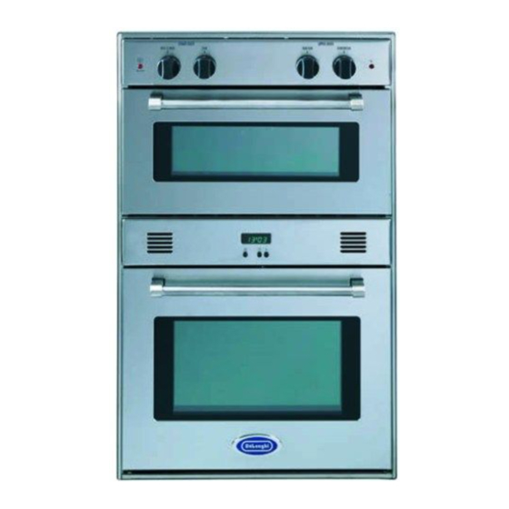
BUILT-IN DUAL FUEL DOUBLE OVEN
for residential use only
DEBIGE 2440 SS
Models:
DEBIGE 2440 E
DEBIGE 2440 W
• USERS OPERATING INSTRUCTIONS
• INSTALLATION ADVICE
•
IMPORTANT - PLEASE READ AND FOLLOW
IMPORTANT - PLEASE READ AND FOLLOW
Before beginning, please read these instructions completely and carefully.
Do not remove permanently affixed labels, warnings, or plates from the product. This
may void the warranty.
Please observe all local and national codes and ordinances.
Please ensure that this product is properly grounded.
The installer should leave these instructions with the consumer who should retain
for local inspector's use and for future reference.
The electrical plug should always be accessible.
Installation must conform with local codes or in the absence of codes, the National Fuel
Gas Code ANSIZ223.1 - Iatest edition. Electrical installation must be in accordance with the
National Electrical Code, ANSI/NFPA70 - latest edition and/or local codes. IN CANADA:
Installation must be in accordance with the current CAN/CGA-B149.1 National Gas
Installation Code or CAN/CGA-B149.2, Propane Installation Code and/or local codes.
Electrical installation must be in accordance with the current CSA C22.1 Canadian
Electrical Codes Part 1 and/or local codes.
INSTALLATION IN MANUFACTURED (MOBILE) HOME: The installation must conform with
the Manufactured Home Construction and Safety Standard, Title 24 CFR, Part 3280 [for-
merly the Federal Standard for Mobile Home Construction and Safety, Title 24, HUD (Part
280)] or, when such standard is not applicable, the Standard for Manufactured Home
Installations, ANSI/NCSBCS A225.1, or with local codes where applicable.
INSTALLATION IN RECREATIONAL PARK TRAILERS: The installation must conform with
state or other codes or, in the absence of such codes, with the Standard for Recreational
Park Trailers, ANSI A119.5.
Installation of any gas-fired equipment should be made by a Iicensed plumber. A manual
gas shut-off valve must be installed in the gas supply line ahead of the appliance in the gas
stream for safety and ease of service.
DEBIGE 2440 SS model only: This built-in double oven is supplied with a protective film on
steel and aluminium parts. This film must be removed before installing/using the appliance.
Advertisement
Table of Contents

Related Manuals for DeLonghi DEBIGE DEBIGE 2440 E


Summary of Contents for DeLonghi DEBIGE DEBIGE 2440 E
- Page 1 DEBIGE 2440 SS model only: This built-in double oven is supplied with a protective film on steel and aluminium parts. This film must be removed before installing/using the appliance.
- Page 2 WARNING: IF THE INFORMATION IN THIS MANUAL IS NOT FOLLOWED EXACTLY, A FIRE OR EXPLOSION MAY RESULT CAUSING PROPERTY DAMAGE, PERSONAL INJURY, OR DEATH. Do not store or use gasoline or other flammable vapors and liquids in the vicinity of this or any other appliance. WHAT TO DO IF YOU SMELL GAS: •...
- Page 3 Dear Customer, Thank you for having purchased and given your preference to our product. The safety precautions and recommendations reported below are for your own safety and that of others. They will also provide a means by which to make full use of the features offered by your appliance.
-
Page 4: Important Precautions And Recom- Mendations
Do not touch hot parts. Keep children away from the oven when it is in use. For DEBIGE 2440 SS model only: This double oven is supplied with a protective film on steel and aluminium parts. This film must be removed before installing/using the appliance. - Page 5 Never clean the double oven with a high-pressure steam cleaning device, as it may provoke a short circuit. This appliance is intended for use in your household. Never...
-
Page 6: Control Panels
Fig. 1.1 Fig. 1.2 CAUTION: Gas appliances produce heat and humidity in the environment in which they are installed. Ensure that the cooking area is well ventilated following nation- al/local codes. control panels CONTROL PANELS 1. Gas oven thermostat knob (Lower gas oven) 2. - Page 7 WARNING VERY IMPORTANT NOTICE When the cooling fan failure warning light is OFF the cooling fan motor is correctly operating. Both the ovens can be used. When the cooling fan failure warning light is lighted this indicates the malfunctioning of the cooling fan motor. Disconnect the oven from the gas mains and contact the After-Sales Service.
- Page 8 Fig. 2.1 electronic clock/end cooking timer ELECTRONIC CLOCK (fig. 2.1) The electronic alarm is a device which groups the functions of 12 hours clock with illu- minated display and 10 hours alarm. Upon immediate connection of the oven or after a blackout, 12•00 will flash on the dis- play.
-
Page 9: Using The Oven For The First Time
how to use the lower gas oven GENERAL FEATURES The gas oven is provided with two burners: a) Oven burner, mounted on the lower part of the oven (11000 BTU/hr) b) Broil burner, mounted on the upper part of the oven (7000 BTU/hr). USING THE OVEN FOR THE FIRST TIME It is advised to follow these instructions: –... -
Page 10: Oven Cooking
Fig. 3.2 Fig. 3.3 IGNITION OF THE OVEN BURNER The thermostat allows the automatic control of the temperature. The gas delivery to the oven burner is controlled by a two way thermostatic tap (oven and broil burners) with flame-failure device. To light the oven burner operate as follows: 1) Open the oven door to its full extent. -
Page 11: Oven Light
IGNITION OF THE BROIL BURNER The broil burner generates the infra-red rays for broiling. To light the broil burner operate as follow: 1) Open the oven door to the full extent. WARNING: Risk of explosion! The oven door must be open during this operation. 2) Lightly press and turn the thermostat knob clockwise to the (fig. - Page 12 Fig. 3.8 WRONG Fig. 3.9 CORRECT Fig. 3.10 1° STEP 2° STEP 3° STEP 4° STEP BROILING Very important: the broil burner must always be used with the oven door closed. – Position the shelf on the second level from the top (fig. 3.7). –...
-
Page 13: Operating Principles
how to use the upper electric oven GENERAL FEATURES As its name indicates, this is an oven that presents particular features from an opera- tional point of view. In fact, it is possible to insert 4 different programs to satisfy every cooking need. The 4 positions, thermostatically controlled, are obtained by 3 heating elements which are: - Lower element... -
Page 14: Function Selector Knob
Fig. 4.2 FUNCTION SELECTOR KNOB Rotate the knob clockwise to set the oven to one of the following functions: OVEN LIGHT By turning the function selector knob to this setting, the oven light will illuminate in the oven cavity (15W). The oven light will operate on all selected functions. -
Page 15: Cooking Advice
BROILING The infra-red broil heating element is switched on. The heat is diffused by radiation. Use with the oven door closed and the temperature selector knob can be regulated between position (see “TEMPERATURE SETTING TABLE”). We suggest to set the temperature selector knob on For correct use see chapter “VENTILATED BROILING AND BROILING”. - Page 16 Fig. 4.4 WRONG Fig. 4.5 CORRECT Fig. 4.6 STEP VENTILATED BROILING AND BROILING Very important: the broil or ventilated broil must always be used with the oven door closed. • Position the shelf on the fourth or fifth level from the top (fig. 4.3). •...
-
Page 17: Cleaning And Maintenance
cleaning and maintenance GENERAL RECOMANDATION Important: Before any operation of cleaning and maintenance disconnect the appliance from the electrical supply. It is advisable to clean when the appliance is cold and especially for cleaning the enamelled parts. Avoid leaving alkaline or acidic substances (lemon juice, vinegar, etc.) on the surfaces. -
Page 18: Replacing The Oven Light
Fig. 5.1 Fig. 5.3 UPPER ELECTRIC OVEN ACCESSORIES INSTALLATION AND REMOVAL – Hang up the wire racks “A” on the upper oven walls (fig. 5.1). – Slide in, on the guides, the shelf etc. (fig. 5.2). Do not use the first three steps from the top. -
Page 19: Removing The Oven Doors
OVEN DOORS The internal glass of the oven doors can be easily removed for cleaning by unscrewing the two fixing screws (figs. 5.5 - 5.6). Do not store flammable material in the ovens. REMOVING THE OVEN DOORS To facilitate oven cleaning, it is possible to remove the door. Please follow the instructions carefully: –... -
Page 20: Do's And Do Not's
DO’S AND DO NOT’S • Do always broil with the oven door closed. • Do read the user instructions carefully before using the oven for first time. • Do allow the oven to heat for one and a half hours, before using for the first time, in order to expel any smell from the new oven insulation, without the introduction of food. -
Page 21: Installation Instructions
INSTALLATION INSTRUCTIONS WARNING! THIS APPLIANCE HAS TO BE INSTALLED BY A QUALIFIED INSTALLER. Improper installation, adjustment, alteration, services, or maintenance can cause injury or property damage. Consult a qualified installer, service agent, or the gas supplier. IMPORTANT: The use of suitable protective clothing/gloves is recommended when handling, installing of this appliance. CAUTION ! Some cabinets and building materials are not designed to withstand the heat produced by the normal safe operation of the appli- ance. -
Page 22: General Information
GENERAL INFORMATION 1. Installation must conform with local codes or, in the absence of local codes, with the National Fuel Gas Code, ANSI Z223.1-Latest Edition. 2. Installation in manufactured (mobile) home: installation must conform with the Manufactured Home Construction and Safety Standard, Title 24 CFR, Part 3280 [formerly the Federal Standard for Mobile Home Construction and Safety, Title 24, HUD (Part 280)] or, when such standard is... -
Page 23: Installation
Taking care NOT to lift the oven by the door handle. This oven may be installed to 24" minimum (609.5 mm) wide cabinets Oven dimensions (fig. 6.1): • width = 24" (609.5 mm); • depth = 21" 3/4 (553 mm); •... - Page 24 Fig. 6.3 Provide a hole for gas connection to 1/2" diameter pipe fitting. Fig. 6.4 Gas line opening: Provide a suitable hole on the bottom of cutout. The centre of hole shall be 10" 1/16 (255.5 mm) from the centre of cutout to the left side and 20"...
-
Page 25: Gas Connection
Explosion Hazard Use a new CSA or UL approved gas supply line. Install a shut-off valve. Securely tighten all gas connec- tions. If connected to LP, have a quali- fied person make sure gas pres- sure does not exceed 14" water column. - Page 26 PRESSURE REGULATOR INSTALLATION STEP 1 Mount the 3/8” NPT (conical) male connector to the pressure regulator and tighten by using a wrench. Do not over tighten the connector. LOCK Over tightening may crack regulator. Arrow Fig. 7.2a STEP 2 Assemble the 3/8” NPT connector + pressure regulator group to the manifold interposing the gasket supplied. The regulator cover must be oriented toward the back of the cabinet.
- Page 27 GAS CONNECTION SPECIFICATION Manifold male pipe fitting Gasket 3/8” NPT (conical) male Pressure regulator Oven manifold 1/2” G cylindrical (ISO 228-1) male 1/2” G cylindrical (ISO 228-1) female Connector 3/8” NPT female 3/8” NPT female WARNING: check the right positioning of the gas regulator.
-
Page 28: Flexible Connections
b) Any conversion required must be performed by your dealer or a qualified licensed plumber or gas service company. Please provide the service person with this manual before work is started on the oven. (Gas conversions are the responsibility of the dealer or end user.) c) This oven can be used with NATURAL or LP/PROPANE gas. -
Page 29: Conversion To Lp/Propane Gas
5. Leak Testing: IMPORTANT: Leak testing of the appliance shall be conducted as follows: • After final gas connection is made, turn on manual gas valve and test all connections in gas supply piping and appliance for gas leaks with a soapy water solution. - Page 30 Fig. 7.6 Fig. 7.7 Fig. 7.8 Fig. 7.9 OPERATIONS TO BE EXECUTED FOR THE REPLACEMENT OF THE INJECTORS OF THE OVEN AND BROIL BURNERS a) oven burner – Lift and remove the lower panel inside the oven. – Remove the burner securing screw (fig. 7.6) –...
-
Page 31: Adjustment Of The Oven Burner Minimum
ADJUSTMENT OF THE OVEN BURNER MINIMUM This needs to be done only for the oven burner (the broil is a fixed capacity) by acting on the thermostat in the following way: – Turn on the burner by setting the thermostat knob on position –... -
Page 32: Electrical Connection
WARNING Electrical Shock Hazard Plug into a grounded 3-prong outlet. Do not remove ground prong. Do not use an adapter. Failure to follow these instructions can result in death, fire, or electrical shock. WARNING VERY IMPORTANT Before any operation of maintenance disconnect the appliance from the electrical mains supply. -
Page 33: Lower Oven
Electric diagram key LOWER OVEN Switch Security microswitch Cooling fan failure lamp Oven lamp Air switch Cooling fan Thermal overload Ignition switch Ignition coil UPPER OVEN Oven switch Oven thermostat Thermostat pilot lamp Air switch Oven lamp Top element Broil element Bottom element Security thermostat Cooling fan... - Page 36 The manufacturer cannot be held responsible for possible inaccuracies due to printing or transcription errors in the present booklet. The manufacturer reserves the right to make all modifications to its products deemed necessary for manufacture or commercial reasons at any moment and without prior notice, without jeopardising the essential functional and safety characteristics of the appliances.