Table of Contents
Advertisement
CALIFORNIA PROPOSITION 65 WARNING
WARNING. This product can expose you to chemicals
including gasoline engine exhaust, which is known to the State
of California to cause cancer, and carbon monoxide, which is
known to the State of California to cause birth defects or other
reproductive harm.
For more information go to www.p65warnings.ca.gov
Operator's Guide
40 / 50 / 60 / 65 / 75 / 90 HORSEPOWER
Original instructions
*216973*
Original
Advertisement
Table of Contents

Related Manuals for BRP Evinrude E-TEC 40


Summary of Contents for BRP Evinrude E-TEC 40
- Page 1 CALIFORNIA PROPOSITION 65 WARNING WARNING. This product can expose you to chemicals including gasoline engine exhaust, which is known to the State of California to cause cancer, and carbon monoxide, which is known to the State of California to cause birth defects or other reproductive harm.
- Page 3 Evinrude® Evinrude® XD30™ S.A.F.E.™ Evinrude® E-TEC® BRP Logo SystemCheck™ Evinrude® Genuine Parts 2+4™ Fuel Conditioner Triple-Guard™ Grease Evinrude® XD100™ HPF Pro™ Gearcase Lubricant RPM Tune™ Evinrude® XD50™ Evinrude ICON™ Remote Control PowerSync™ © 2018 BRP US Inc. All rights reserved.
-
Page 4: Table Of Contents
Remote Control Models – Engine Starting / Stopping ....30 Remote Controls - Evinrude (BRP) Controls ......33 Fuel Economy . - Page 5 Pre-Ride Inspection .......51 Aquatic Invasive Species (AIS) .....52 Clean, Drain &...
-
Page 6: About This Guide
About This Guide This Operator’s Guide is an essential part of This Operator’s Guide uses the following sig- your Evinrude E-TEC outboard. It contains nal words identifying important safety mes- pertinent information which, if followed, will sages. provide you with a thorough understanding needed for proper operation, maintenance, DANGER care, and—above all—safety. -
Page 7: Important Safety Messages
Important Safety Messages This Operator’s Guide contains essential in- – Remember, gasoline fumes are flamma- formation to help prevent personal injury and ble and explosive. Always adhere to the damage to equipment. Safety messages ap- fueling procedure contained in this Oper- pear throughout this Guide in the applicable ator’s Guide and those given to you by section. - Page 8 Safety Measures — Installation and – Be familiar with the waters you are oper- Maintenance ating in. The gearcase of this outboard extends below the water surface and – The outboard must be correctly installed. could potentially come in contact with un- Failure to correctly install the outboard derwater obstructions.
-
Page 9: Product References, Illustrations And Specifications
Product References, Illustrations and Specifications BRP reserves the right to make changes at any time, without notice, to features, specifications and model availability, and to change any specification or part at any time without incurring any obligation to update older models. The information in the Guide is based on the latest specifications available at the time of publication. -
Page 10: Declaration Of Conformity
Declaration of Conformity The EC Declaration of Conformity does not appear in this version of the Operator's Guide. Please refer to the printed version that was delivered with your engine. -
Page 11: Using Your Evinrude E-Tec Outboard
Using Your Evinrude E-TEC Outboard... -
Page 12: Important On-Product Labels
Guide before proceeding.” Operator's Guide 1. Read Operator’s Guide Label 355633 EMISSION CONTROL INFORMATION - BRP US INC. THIS ENGINE CONFORMS TO U.S. EPA & CALIFORNIA EMISSIONS/EVAP REGULATIONS FOR MARINE SI ENGINES RENSEIGNEMENTS SUR LE DISPOSITIF ANTIPOLLUTION CE MOTEUR EST CONFORME AUX NORMES DE L'EPA DES É. - Page 13 Important On-Product Labels Hang Tag Hang Tag – Pontoon Series Outboards All outboards are shipped with the following hang tag attached. WARNING Pontoon Series outboards are intended to be installed ONLY on pontoon boats. Operator's Guide Boat hulls other than pontoons may experience instability steering...
-
Page 14: Dr Models
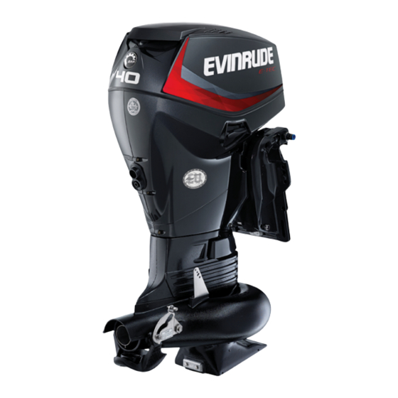
Using Your Evinrude E-TEC Outboard Component Identification – DR Models 008808 Item Description Item Description Air Inlet, Tilt Handle Fuel Fitting Water Pump Indicator, Flushing Port Tilt Support Engine Cover Latch Water Intake Screens Anti-Corrosion Anodes... - Page 15 Component Identification – DR Models Starboard 008809 Port 008810 Item Description Item Description Engine Cover Latch Starter handle Spark Plugs Oil Fill Cap Fuel Filter Oil Tank Flywheel Guard EMM (Engine Management Module) Air Silencer...
-
Page 16: Dg, Dh, Dpg, Dpj, Dpx, Ds, Dt, Gl, Sl & Snl Models
Using Your Evinrude E-TEC Outboard Component Identification – DG, DH, DPG, DPJ, DPX, DS, DT, GL, SL & SNL Models 002010 Item Description Item Description Air Inlet, Tilt Handle Fuel Fitting (3/8 inch) Water Pump Indicator, Flushing Port Oil Fitting (1/4 inch) Pontoon Series only Engine Cover Latch Tilt Support... - Page 17 Component Identification – DG, DH, DPG, DPJ, DPX, DS, DT, GL, SL & SNL Models Starboard 002009 Port 002008 Item Description Item Description Engine Cover Latch Trailering Tilt Switch Spark Plugs Spare Fuse Fuel Filter Fuse Flywheel Guard Oil Fill Cap Air Silencer Oil Tank EMM (Engine Management Module)
-
Page 18: Tiller Handle, Dr Models
Using Your Evinrude E-TEC Outboard Component Identification – Tiller Handle, DR Models 008811 Item Description Item Description Shift Lever Throttle Friction Screw Stop Button/Engine Cut-out Switch Clip and Tether Cord Assembly Steering Handle Twist Grip Throttle... -
Page 19: Tiller Handle, Dtl Models
Component Identification – Tiller Handle, DTL Models 008812 Item Description Item Description Key Switch Steering Handle Twist Grip Throttle Shift Lever Throttle Friction Screw Stop Button/Engine Cut-out Switch Clip and Tether Cord Assembly Trim Switch (DTL Models Only) -
Page 20: Oil And Fuel
Using Your Evinrude E-TEC Outboard Oil and Fuel Oil Requirements Other Oils If Evinrude brand oils are not available, you Evinrude Brand Oils must use an oil that meets NMMA TC-W3 cer- tification standards. NOTICE Failure to follow oil specifications could void the engine warranty if a lubrication-related When operating in conditions under 32°F failure occurs. - Page 21 Oil and Fuel Filling the Oil Tank Outboards Without Remote Oil Tank Fill to bottom of filler neck. Release the port and starboard engine cover latches by turning each handle downward. 1. Bottom of filler neck C04-009054 002015 Outboards With Remote Oil Tank Pull up on the tilt handle to release the engine Fill to “Max Fill Line.”...
-
Page 22: Remote Oil Tank System
Using Your Evinrude E-TEC Outboard Remove the filler cap and fill the tank with the Oil Temperature Approximate Time to Fill recommended outboard lubricant, as speci- °F (°C) to Max Level (minutes) fied in Oil Requirements on page 18. 90°– 120° (32°– 49°) 60°–... -
Page 23: Fuel Requirements
Oil and Fuel Fuel Requirements Recommended Fuel: Use unleaded gaso- line with an AKI (R+M)/2 octane rating of 87, WARNING or an RON octane rating of 90. Gasoline is extremely flammable and Biobutanol (Bu16) Fuel highly explosive under certain condi- Biobutanol is a four-carbon alcohol produced tions. - Page 24 Using Your Evinrude E-TEC Outboard Fueling Procedure Always follow the instructions provided with the fuel tank and cap. WARNING On a Trailer Fuel is flammable and explosive under certain conditions. Follow these instruc- WARNING tions to ensure safety when handing To prevent fuel back-flow, fill the fuel fuel: tank slowly so air can escape from tank.
-
Page 25: Fuel System Information
Oil and Fuel Fuel Additives result in a loss of performance. If a perfor- mance problem exists, see your Dealer. NOTICE Fuel Filters Use of other fuel additives can result in A boat-mounted water-separating fuel filter poor performance or engine damage. assembly will help prevent water and other contaminants from entering the engine fuel The only fuel additives approved for use in... -
Page 26: Operation
Using Your Evinrude E-TEC Outboard Operation Safety Information Tiller Models – Engine Starting / Stopping DANGER NOTICE Serious injury or death can result from contact with a rotating propeller or mov- Carefully check the function of all con- ing boat and outboard. trol and engine systems before leaving Propeller blades can be sharp and the the dock. - Page 27 Operation Engine Cut–off Switch might tear away instead of activating the en- gine cut–off switch. WARNING Always use the tether cord when operat- ing your boat to help prevent a runaway boat and reduce the risk of personal injury or death. Avoid knocking or pulling the clip off the engine cut–off switch during normal boating.
- Page 28 Using Your Evinrude E-TEC Outboard Starting DO NOT advance the throttle before start-up. Advancing the throttle overrides the electronic WARNING idle control system. Always shift to NEUTRAL before starting If the outboard is started with the throttle ad- the outboard to prevent sudden boat vanced, the outboard will be in a safety mode.
- Page 29 Operation If the engine did not start, release the key mo- Tiller Electric Models mentarily, then try again. NOTICE IMPORTANT: Engine will not start if outboard The starter motor can be damaged if is in gear or if tether cord is not in place. operated continuously for more than 20 If your outboard does not react normally to seconds.
- Page 30 Using Your Evinrude E-TEC Outboard Shifting Outboard may be stopped by turning the key switch to the OFF position, or by pressing the NOTICE engine cut–off switch until the outboard stops running. When shifting from FORWARD REVERSE or from REVERSE to FOR- IMPORTANT: Be sure to turn key OFF when outboard is not in use to avoid discharging the WARD, pause at NEUTRAL until the...
- Page 31 Operation Fuel Economy Tiller Handle Angle Tiller handle angle can be raised or lowered Fuel economy can vary depending on boat by turning the adjustment screw under the load, hull design, and throttle setting. When handle. boat reaches top speed, throttle back from FULL SPEED to a lower throttle setting.
-
Page 32: Remote Control Models - Engine Starting / Stopping
Using Your Evinrude E-TEC Outboard Remote Control Models – Engine WARNING Starting / Stopping Avoid knocking or pulling the clip off the NOTICE engine cut–off switch during normal boating. Avoid bumping the key if oper- Carefully check the function of all con- ating without the clip on the switch. - Page 33 Operation tether cord for cuts, breaks, or wear. Replace DO NOT advance the throttle before start-up. worn or damaged parts. Advancing the throttle overrides the electronic idle control system. Snap the tether cord to a secure place on the operator’s clothing or life vest —...
- Page 34 Using Your Evinrude E-TEC Outboard Engine Stopping Move control handle to NEUTRAL. Turn key switch counterclockwise to the OFF position. START START 1. Key switch START position 007015A Upon start-up, release the key. If the engine did not start, release the key mo- mentarily, then try again.
-
Page 35: Remote Controls - Evinrude (Brp) Controls
Operation Remote Controls - Evinrude (BRP) Controls WARNING If you choose a non-Evinrude remote control, it must have a start-in-gear prevention feature. This feature can prevent injuries resulting from unexpected boat movement when the engine starts. IMPORTANT: When selecting the remote control system for your boat, specify Evinrude com- ponents. -
Page 36: Fuel Economy
Using Your Evinrude E-TEC Outboard Shifting Binnacle Mount Controls Move the control handle with a firm, quick mo- NOTICE tion, forward or aft until it engages the forward or reverse gear detent. When shifting from FORWARD REVERSE or from REVERSE to FOR- WARD, pause at NEUTRAL until the NEUTRAL engine is at idle speed and the boat has... -
Page 37: Emergency Starting
Operation Emergency Starting 2) Remove fuse holder from flywheel cover. WARNING Move the shift lever to NEUTRAL before performing emergency starting proce- dures. Failure to do so may result in unexpected boat movement. The engine cover is a machinery guard. To prevent injury from moving engine components, keep hands, clothes, and hair clear of powerhead. - Page 38 Using Your Evinrude E-TEC Outboard 5) Hook the knot of the emergency start cord 7) Turn key switch ON. into the notch on the flywheel that is oppo- site the starter shaft. CAUTION Next, wind the cord clockwise in the groove Keep everyone clear of your immediate of the flywheel.
-
Page 39: Tilting And Trim - Manual Tilt Models
Tilting and Trim – Manual Tilt Models Trim Angle Adjustment WARNING Boat stability and steering torque can vary due to changing water conditions. If any adverse conditions occur, reduce throttle and/or adjust tilt angle to maintain control. If you experience boat instability and/or high steering torque, see your Dealer to cor- rect these conditions. - Page 40 Using Your Evinrude E-TEC Outboard DR Models Tilt DOWN NOTICE WARNING Operate outboard in normal operating Leave tilt/run lever in the TILT position position with tilt/run lever in the RUN while outboard is tilted. If the tilt/run position. lever is moved to the RUN position, the tilt support bracket can release and the Move tilt/run lever to RUN position.
- Page 41 Tilting and Trim – Manual Tilt Models Engage Disengage 1) Move the tilt/run lever to TILT position. 1) Move tilt/run lever to RUN position. 2) Tilt the outboard UP. 2) Tilt the outboard UP. 3) Push tilt support bracket to “lock” position. 3) Pull tilt support bracket to “unlock”...
-
Page 42: Tilting And Trim - Power Trim And Tilt Models
Using Your Evinrude E-TEC Outboard Tilting and Trim – Power Trim and Tilt Models WARNING Any malfunction of the power trim and tilt unit could result in loss of shock absorber protection if an underwater obstruction is hit. Malfunction can also result in loss of reverse thrust capability. - Page 43 Tilting and Trim – Power Trim and Tilt Models Trim Angle Adjustment Use the trim/tilt switch to adjust the outboard position in the tilt range or trim range. Run the boat in the water to determine the best trim angle. IMPORTANT: Weight distribution can affect the performance of the boat.
- Page 44 Using Your Evinrude E-TEC Outboard 3) Lower the outboard until the tilt support le- If needed, the outboard will tilt up or down ver rests solidly on the stern brackets. manually, using the manual release valve. 1) Turn the manual release screw counter- clockwise, slowly (about 3 1/2 turns), until it lightly contacts its retaining ring.
- Page 45 Tilting and Trim – Power Trim and Tilt Models Impact Damage Protection NOTICE WARNING The outboard’s shock absorption system does work while operating Failure to inspect for damage after an reverse. If you back into an object, either accident or striking an object could in the water or while trailering, your boat result in sudden, unexpected component and outboard can be seriously damaged.
-
Page 46: Engine Monitoring
Using Your Evinrude E-TEC Outboard Engine Monitoring IMPORTANT: All outboards, except tiller TEST MODE IN OPERATION. When the self steering models, must be equipped with an test is complete, the gauges will beep a final engine monitoring system such as ICON Pro, time and then display SELF TEST COM- SystemCheck, or equivalent. -
Page 47: Engine Overheating
Engine Monitoring The following warnings may appear on the ists, the engine will operate in “get home” engine monitor gauge. mode. Return to harbor immediately. • A flashing light — The EMM has identified “LOW OIL” a damaging overheating condition. The en- gine will not operate. - Page 48 Using Your Evinrude E-TEC Outboard structed. Observe proper trim angle. While IF cleaning the screens and indicator does re- the outboard is running, the outboard’s water store the water pump indicator’s steady dis- pump indicator must discharge a steady charge, allow the engine to run for two stream of water.
-
Page 49: Special Operating Conditions
Special Operating Conditions Cold and Freezing Weather Salt Water Anode protection for the outboard has been NOTICE provided for use in salt or brackish water. When operating in conditions under 32°F Upon removal from salt water, leave outboard (0°C), Evinrude XD100 oil, must be used. in a vertical position until its cooling system has drained. -
Page 50: Shallow Water
Using Your Evinrude E-TEC Outboard Shallow Water 3-Cylinder Models Gearcase damage can occur if the gearcase is allowed to drag on the waterway bottom. Use caution when operating in shallow water. IMPORTANT: Impact damage is NOT cov- ered by the outboard warranty. Under Tow Should you require a tow from another boat: •... -
Page 51: Transporting The Outboard
Transporting the Outboard Power Trim and Tilt Models WARNING WARNING If engine is equipped with a quick-dis- connect fuel hose, you MUST disconnect Keep everyone clear of stern area when the fuel hose from the engine and the raising or lowering the outboard. Per- fuel tank to prevent fuel leaks: sonal injury or death can result from contact with moving parts of the out-... -
Page 52: Transporting / Storage
Using Your Evinrude E-TEC Outboard Transporting / Storage Pull down the trailering bracket. A detent will hold the bracket in position. WARNING A small amount of fuel may be released when the fuel line is disconnected. Always wipe off any fuel spillage. Gasoline is extremely flammable and highly explosive under certain condi- tions. -
Page 53: Pre-Ride Inspection
Pre-Ride Inspection WARNING Always perform a pre-ride inspection before operating the boat. Check the proper operation of critical controls, safety features and mechanical components. Correct any problems BEFORE leaving the dock. Make sure all safety equipment required by local law is onboard. The engine(s) should be OFF and the tether cord must always be removed from the engine cut-off switch before verifying any of the following. -
Page 54: Aquatic Invasive Species (Ais)
Using Your Evinrude E-TEC Outboard Aquatic Invasive Species (AIS) Clean, Drain & Dry – Aquatic Invasive Species (AIS) are non-na- tive plant or animal species that threaten the Everything, Every Time! diversity or abundance of the native species. They also threaten the natural ecology of the Before you leave a waterway, follow the pro- body of water they infest. -
Page 55: Ais Inspection Checklist
Aquatic Invasive Species (AIS) AIS Inspection Checklist Use the following checklist as a guide when inspecting for AIS. Inspection Items Inspect hull. Inspect floor. Inspect live well. Inspect transom well. Boat Inspect water inlet & outlet fittings. Inspect anchors and lines. Inspect boarding ladder. - Page 57 Maintenance...
-
Page 58: Engine Emissions Installation Information
A repair shop or person of the owner's choosing may maintain, replace, or repair emission control devices and systems. These instructions do not require components or service by BRP or authorized Evinrude dealers. Although an authorized Evinrude dealer has the in-depth tech-... - Page 59 EPA Emission Regulations All new 1999 and more recent Evinrude outboards manufactured by BRP are certified to the EPA as conforming to the requirements of the regulations for the control of air pollution from new watercraft marine spark ignition engines. This certification is contingent on certain adjust- ments being set to factory standards.
-
Page 60: Maintenance Schedule
Maintenance Maintenance Schedule Routine inspection and maintenance is necessary to prolong outboard life. The following chart provides guidelines for inspection and maintenance to be performed by an authorized Dealer. IMPORTANT: Outboards used in rental, commercial, or other high hour applications require more frequent inspections and maintenance. -
Page 61: Service
Service Anti-Corrosion Anodes mize the accumulation of scale and silt depos- its in cooling system passages. The outboard NOTICE can be flushed on the trailer or at dockside. Place outboard in vertical (down) position in a NEVER paint the anode, its fasteners, or well ventilated area. -
Page 62: Fuse
Maintenance Using Gearcase Flushing Device Fuse Replacement 1) Place the outboard in an area with good NOTICE drainage. 2) Remove propeller and place the shift lever Use only fuses of the same rating. Your in NEUTRAL position. Evinrude E-TEC outboard uses 10-amp 3) Connect garden hose to flushing device fuses. -
Page 63: Scratch Repair
Service a deep, durable gloss with maximum ultravio- Spark plugs should be serviced by an Evin- let (sunlight) protection. rude E-TEC Dealer. Incorrect spark plug maintenance can lead to engine damage. The high gloss finish will show polish marks when viewed closely in certain light condi- Marine Engine Duty Cycles tions. -
Page 64: Storage
Maintenance Storage WARNING WARNING DO NOT run the engine indoors or with- Prevent injury from moving engine com- adequate ventilation permit ponents. Before starting the outboard: exhaust fumes to accumulate in con- • Shift it to NEUTRAL. fined areas. Engine exhaust contains •... -
Page 65: Long-Term Storage (Winterization)
Storage Long-Term Storage Remote Control Outboards (Winterization) 1) For side mount controls, fully lift the fast idle lever. Start the outboard. Outboard WARNING runs at slow idle speed. Outboard must be in NEUTRAL before performing winterization. Starting out- board in gear can cause personal injury. If winterizing on a trailer, the propeller must be removed before performing pro- cedure. - Page 66 Maintenance Tiller Control Outboards Outboard continues to run at slow idle speed. 1) Fully advance throttle grip. Start the out- board. Outboard runs at slow idle speed. 006458 3) After outboard runs for another 15 sec- Tiller Control – Typical 007036 onds: 007037...
- Page 67 Storage Remote Control Outboards with Foot button and the outboard was shifted into gear. Throttle • If the engine exceeds 3000 RPM, the out- 1) Fully advance the foot throttle. Start the board may have been shifted into gear. outboard.
-
Page 68: Pre-Season Check
Maintenance Pre-Season Check Confirm water pump operation. Water must flow from the water pump indicator in a steady Remove your outboard from storage and pre- stream. If it does not, shut off the outboard pare it for a season of reliable service by per- and investigate. -
Page 69: Troubleshooting
Troubleshooting SYMPTOM POSSIBLE CAUSE • Shift handle not in NEUTRAL. Starter motor will not operate • Fuse blown. • Battery is dead. • Not following starting instructions. Refer to Engine will not start on page 24. Operation • Fuel system not primed after running out of fuel. Refer to on page 24. -
Page 71: Product Information
Product Information... -
Page 72: Installation
Product Information Installation • Refer to Specifications on page 77 for WARNING transom height. Your outboard must not exceed the max- Determine transom height by measuring from imum horsepower indicated on the the top edge of the transom, along the center- boat’s capacity plate. -
Page 73: Installing The Outboard
Installation Installing the Outboard Use the supplied Transom Mounting Kit to se- curely mount the outboard. The kit includes a WARNING transom mounting plate and hardware for fas- tening outboard to transom. outboard must correctly installed. Failure to correctly install the outboard could result in serious injury, death or property damage. -
Page 74: Boat-Mounted Fuel Filters
Product Information Boat-Mounted Fuel Filters Installation Boat-mounted fuel filters and water-separat- WARNING ing fuel filter assemblies must meet the follow- ing requirements: Read and understand the safety informa- tion supplied with your battery BEFORE • Fuel flow – 0.4 in. Hg maximum pressure you begin installation. -
Page 75: Water Pressure
Installation Service WARNING Battery electrolyte is acidic — handle with care. If electrolyte contacts any part of the body, immediately flush with water and seek medical attention. Do not use a booster battery and jumper cables to start the outboard. Gasoline fumes can cause explosion and fire, resulting in property damage, personal injury or death. -
Page 76: Propeller
Product Information Propeller Wedge a block of wood between the propeller blade and the anti-ventilation plate. Propeller Selection Install propeller nut and 20 Inch Models — tighten to a torque of 120-144 in. lbs. (13.6- WARNING 16.3 N·m). When servicing the propeller, always Install propeller nut and 25 Inch Models —... -
Page 77: Adjustments
Adjustments Friction If adjustment is necessary, turn the adjust- ment screw: • Clockwise to increase friction; or Throttle Friction • Counterclockwise to decrease friction. WARNING Tighten knob only enough to hold throt- tle at a constant engine speed. Over tightening will prevent quick throttle change in case of emergency. - Page 78 Product Information Tilt Limiter Cam – 3-Cylinder Models the boat pulled to the left, move the rear of the trim tab slightly to the left. With Power Trim and Tilt WARNING Adjusting the tilt limiter cam will NOT prevent the outboard from tilting fully and contacting the motor well if the gear- case hits an object at high speed.
-
Page 79: Specifications
Specifications 40, 50, 60, Models Displacement 52.7 cu. in. (864 cc) Engine Type In-line, 2 Cylinder, Two-Cycle, E-TEC 40 HP – 5000 to 6000 RPM 40 HO – 5500 to 6000 RPM Full Throttle Operating Range 50 HP – 5500 to 6000 RPM 40 Jet / 60 HP –... - Page 80 Product Information Specifications 60 H.O., 65, 75, 90 Models Displacement 79.1 cu. in. (1296 cc) Engine Type In-line, 3 Cylinder, Two-Cycle, E-TEC Full Throttle Operating Range 60 H.O. – 5000 to 5500 RPM 65 HP – 5000 to 5500 RPM 75 HP –...
-
Page 81: Product Warranty Information
• Damage resulting from removal of parts, improper repairs, service, maintenance, or modification, or use of parts or accessories not manufactured or approved by BRP, which in its reasonable judgment, are either incompatible with Product or adversely affect its operation, performance, or durability, or resulting from repairs done by a person that is not an authorized OE Distributor/Dealer (as described below);... - Page 82 Product other than those contained in this limited warranty and, if made, shall not be enforceable against BRP. BRP reserves the right to modify this limited warranty at any time, being understood that such modification will not alter the warranty conditions applicable to the Prod- ucts sold while this limited warranty is in effect.
- Page 83 The registered owner must notify an authorized servicing OE Distributor/ Dealer within two (2) days of the appearance of a defect. BRP is not responsible for damages caused by the use of a Product after the ap- pearance of a defect. Owner must bring Product, including any defective part therein, to OE Distributor/ Dealer promptly after the appearance of the defect, and in any event, within the warranty period, and must provide OE Distributor/Dealer with reasonable opportunity to repair the defect.
- Page 84 7. What BRP Will Do To the extent permitted by law, BRP's obligations under this limited warranty are limited to, at its sole dis- cretion, repairing or replacing parts of Product found to be defective in material or workmanship, in the reasonable judgment of BRP.
- Page 85 Product Warranty Information Additional Terms and Conditions for France Only The following terms and conditions are applicable to products sold in France only: The seller shall deliver goods that are complying with the contract and shall be responsible for defects existing upon delivery.
- Page 86 40 CFR 1045 and 40 CFR 1060. Where a warrantable condition exists, BRP will repair or replace, as it elects, any part or component with a defect in materials or workmanship that would increase the engine's emissions of any regulated pollutant within the stated warranty period at no cost to the owner, including expenses related to diagnosing and repairing or replacing emission-related parts.
- Page 87 *As related to the evaporative emission control system Limited Applicability As a certifying manufacturer, BRP may deny emission-related warranty claims for failures that have been caused by the owner's or operator's improper maintenance or use, by accidents for which the manufac- turer has no responsibility, or by acts of God.
- Page 88 California Emission Control Warranty Statement Your Evinrude E-TEC G2 outboard has a special environmental label required by the California Air Re- sources Board. The label has one, two, three, or four stars. A hangtag, provided with your outboard, de- scribes the meaning of the star rating system. The Star Label Means Cleaner Marine Engines The Symbol for Cleaner Marine Engines: Cleaner Air and Water...
- Page 89 State's stringent anti-smog standards. BRP must warrant the emission control system on your outboard for the periods of time listed below pro- vided there has been no abuse, neglect, or improper maintenance of your outboard.
- Page 90 As the outboard owner, you are responsible for the performance of the required maintenance listed in your Operator's Guide. BRP recommends that you retain all receipts covering maintenance on your outboard, but BRP cannot deny warranty solely for the lack of receipts or your failure to ensure the performance of all scheduled maintenance.
-
Page 91: Readiness Test
Readiness Test The Operator’s Readiness Test..1. Did you read this Guide from front cover to rear cover? 2. Are you ready to take responsibility for the safe operation of your boat and outboard? 3. Do you understand all the safety precautions and instructions contained in this Guide? 4. -
Page 93: Frequently Asked Questions
No dealer-scheduled maintenance for three years or 300 hours of normal recreational use? Really? • Yes! BRP knows you want to spend your time out on the water, not servicing your Evinrude E-TEC outboard. There are no valves to adjust, belts to service, chains to replace, or oil to change. -
Page 95: Change Of Address / Change Of Ownership
This notification is necessary for your own safety even after expiration of the original warranty, since BRP will be in a position to contact you if correction to your outboard is required. Outside the U.S. and Canada, this card should be sent to the Bombardier Recreational Products division where the outboard was regis- tered. -
Page 97: Confirmation Of Receipt
Confirmation of Receipt Your Dealer Name: Address: Upon delivery of your new Evinrude outboard, complete and sign the form below. Your Dealer will take receipt of the form for their records. Receipt Name: Address: Owner of Model No: Serial No: (To be completed by customer or selling Dealer) The Dealer named on this document has instructed me on the operation, maintenance, safety features and warranty policy, all of which I understand and agree to be bound with.