Table of Contents
Advertisement
Quick Links
CR-IR 362 Service Manual
Installation (IN)
011-207-09E
09.30.2009 FM5539
Control Sheet
Revision
Issue date
Reason
number
08.25.2003
01
New release (FM4098)
10.10.2003
02
Corrections (FM4160)
02.20.2004
03
Corrections (FM4181)
11.15.2004
04
Corrections (FM4425)
05.10.2005
05
Corrections (FM4610)
02.19.2007
07
Change of document number, corrections (FM5097)
09.30.2008
08
Revision (FM5340)
09.30.2009
09E
Revision (FM5539)
CR-IR 362 Service Manual
Pages affected
All pages
13, 23-31, Appx IN-2, 13-18
1, 2, 21-35 , Appx IN-3, 8, 18
2, 4-31, Appx IN-19, 20
Appx IN-8
All pages
8, 9, 28-39
4, 8-47, Appx IN-14, 19
Advertisement
Table of Contents

Related Manuals for FujiFilm CR-IR 362


Summary of Contents for FujiFilm CR-IR 362
- Page 1 13, 23-31, Appx IN-2, 13-18 02.20.2004 Corrections (FM4181) 1, 2, 21-35 , Appx IN-3, 8, 18 11.15.2004 Corrections (FM4425) 2, 4-31, Appx IN-19, 20 CR-IR 362 Service Manual 05.10.2005 Corrections (FM4610) Appx IN-8 02.19.2007 Change of document number, corrections (FM5097) All pages 09.30.2008...
-
Page 2: Specifications Of Machine
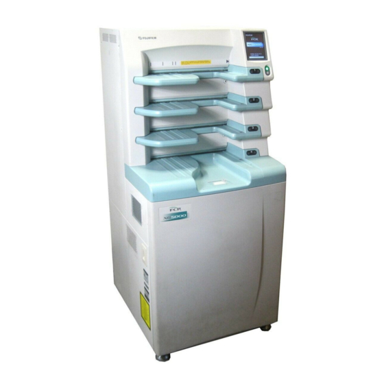
Dimensions W655 × D740 × H1480 (mm) l For fixing by machine retainers n Weight 285 kg approx. n Means for Moving and Fixing the Machine Moving : Double-wheel caster (variable-direction/no-brake) x4 Fixing : - Adjustable foot x4 - Machine retainer x2 IN-1 CR-IR 362 Service Manual 011-207-07E 02.19.2007 FM5097... -
Page 3: Installation Work Flowchart
8.5 Installing RU Software 4.2 Removing the Light Protect Plates 4.3 Repositioning the Retaining Members 9. Image/Conveyance Checks 4.4 Installing the Cover 9.1 Check Before Procedures 5. Connecting the Cables 9.2 Image/Conveyance Checks 5.1 Connecting the Power Cable and Checking 10. Powering OFF the CL/RU Resistance Value 5.2 Connecting the Interface Cable 11. Cleaning the CL/RU Final Placement 6.1 Securing the Cable 6.2 Securing the Machine IN-2 CR-IR 362 Service Manual 011-207-07E 02.19.2007 FM5097... -
Page 4: Preparation For Installation
IEC60601-1-1. Everyone who connects additional equipment configures a medical system, and is therefore responsible that the system complies with the requirements of IEC60601-1-1. If in doubt consult with the your local technical service representative." IN-3 CR-IR 362 Service Manual 011-207-07E 02.19.2007 FM5097... - Page 5 3. Wooden materials are added to four corners inside the crate. When you see the detail of changes, refer to “Appendix 5. Changes in the Packaging Specifications”. {IN: Appendix 5._Changes in the Packaging Specifications} IN-4 CR-IR 362 Service Manual 011-207-09E 09.30.2009 FM5539...
- Page 6 - The removed crate should be moved away to an unobstructive place. Incline the crate to take it out. CAUTION When removing the crate, incline the crate to take it out. If you try to move the crate, it might hit the machine, thereby damaging the machine. IN-5 CR-IR 362 Service Manual 011-207-07E 02.19.2007 FM5097...
- Page 7 - Because the crate is assembled with nails, hit it with a hammer or the like from Remove the lower portion of the barrier bag that protects the machine. inside to break up the crate. - Use care not to get injured by protruding nails when breaking up the crate. IN-6 CR-IR 362 Service Manual 011-207-07E 02.19.2007 FM5097...
- Page 8 When the nut is loosened, the machine may incline by its own weight. So, use care not to get your finger pinched by the machine retainer or adjustable foot. IN-7 CR-IR 362 Service Manual 011-207-07E 02.19.2007 FM5097...
- Page 9 IN-8 CR-IR 362 Service Manual 011-207-09E 09.30.2009 FM5539...
- Page 10 Lower the machine from the carrier pallet. CAUTION When lowering the machine from the carrier pallet, one person should be positioned on the right-hand side of the machine, and the other on its left-hand side. IN-9 CR-IR 362 Service Manual 011-207-09E 09.30.2009 FM5539...
- Page 11 The removed crate should be moved away to an unobstructive place. Move down the machine together with the carrier pallet from the load- carrying platform of the truck. REFERENCE - The following label is attached to the crate. - In case of machines for China, a label in Chinese is attached. IN-10 CR-IR 362 Service Manual 011-207-09E 09.30.2009 FM5539...
- Page 12 - Because the crate is assembled with nails, hit it with a hammer or the like from inside to break up the crate. - Use care not to get injured by protruding nails when breaking up the crate. IN-11 CR-IR 362 Service Manual 011-207-09E 09.30.2009 FM5539...
- Page 13 IN-12 Remove the accessories-containing bug. Lower the adjustable feet bolts to lift up the machine. CAUTION Unless the machine is lifted up by the adjustable feet, the machine retainers could not be removed. Remove the lower portion of the barrier bag that protects the machine. IN-12 CR-IR 362 Service Manual 011-207-09E 09.30.2009 FM5539...
- Page 14 When the nut is loosened, the machine may incline by its own weight. So, use care not to get your finger pinched by the machine retainer or adjustable foot. care not to get your finger pinched by the machine retainer or adjustable foot. IN-13 CR-IR 362 Service Manual 011-207-09E 09.30.2009 FM5539...
- Page 15 Lower the machine from the carrier pallet. CAUTION Raise the adjustable feet up to their upper limit. When lowering the machine from the carrier pallet, one person should be positioned on the right-hand side of the machine, and the other on its left-hand side. IN-14 CR-IR 362 Service Manual 011-207-09E 09.30.2009 FM5539...
- Page 16 IN-15 3.2.3 Unloading (#50001 or Later): Other than countries Clear the fixing nail, and remove the cardboard. specifying the crate Move down the machine together with the carrier pallet from the load- carrying platform of the truck. Cut the PP band, and remove the top plate. IN-15 CR-IR 362 Service Manual 011-207-09E 09.30.2009 FM5539...
- Page 17 IN-16 Remove the accessories-containing bug. Lower the adjustable feet bolts to lift up the machine. CAUTION Unless the machine is lifted up by the adjustable feet, the machine retainers could not be removed. Remove the lower portion of the barrier bag that protects the machine. IN-16 CR-IR 362 Service Manual 011-207-09E 09.30.2009 FM5539...
- Page 18 When the nut is loosened, the machine may incline by its own weight. So, use care not to get your finger pinched by the machine retainer or adjustable foot. care not to get your finger pinched by the machine retainer or adjustable foot. IN-17 CR-IR 362 Service Manual 011-207-09E 09.30.2009 FM5539...
- Page 19 Lower the machine from the carrier pallet. CAUTION When lowering the machine from the carrier pallet, one person should be Raise the adjustable feet up to their upper limit. positioned on the right-hand side of the machine, and the other on its left-hand side. IN-18 CR-IR 362 Service Manual 011-207-09E 09.30.2009 FM5539...
-
Page 20: Temporary Placement
Note that the step over which the machine may move is about 10 mm high at most. Put the hand lifter underneath the machine. u INSTRUCTION u The hand lifter should be oriented aslant with respect to the machine. Secure the machine with the adjustable feet in place. Transfer the machine into the installation place. IN-19 CR-IR 362 Service Manual 011-207-09E 09.30.2009 FM5539... -
Page 21: Checking The Items Supplied
Machine AC power cable for use in U.S. Machine AC power cable for use in Europe (excluding U.K.), TUV certified Machine AC power cable for use in U.K., TUV certified Anti-topple retainer kit For retaining the machine Both-side cassette identification barcode reader IN-20 CR-IR 362 Service Manual 011-207-09E 09.30.2009 FM5539... -
Page 22: Installation Procedures
IN-21 4. Installation Procedures l #50001 or Later 4.1 Removing Tapes from the Machine Remove the tapes. l #20001 or Later IN-21 CR-IR 362 Service Manual 011-207-09E 09.30.2009 FM5539... - Page 23 IN-22 4.2 Removing the Light Protect Plates 4.3 Repositioning the Retaining Members REFERENCE Remove the lower front cover. The retaining members may be removed along the rope. Remove the upper retaining member. Remove the lower light protect plate. IN-22 CR-IR 362 Service Manual 011-207-09E 09.30.2009 FM5539...
- Page 24 IN-23 Reposition the lower retaining members. Reposition the lower retaining members. IN-23 CR-IR 362 Service Manual 011-207-09E 09.30.2009 FM5539...
-
Page 25: Installing The Cover
When the "both-side cassette identification barcode reader" is to be installed to prevent wrong insertion of a cassette, see "Appendix 4 Setting the Both-Side Cassette Identification Barcode Reader" {IN: Appendix 4._Setting the Both-Side Cassette Identification Barcode Reader} IN-24 CR-IR 362 Service Manual 011-207-09E 09.30.2009 FM5539... -
Page 26: Connecting The Cables
Cable certified by a country in which the machine is to be installed Cable wire diameter: 1.0 mm2 or larger, 3-conductor Rated voltage: 250 VAC or higher Cable type: H05VV-F Cable length: 3 m or shorter IN-25 CR-IR 362 Service Manual 011-207-09E 09.30.2009 FM5539... - Page 27 IN-26 Place the breaker switch in the OFF position. IN-26 CR-IR 362 Service Manual 011-207-09E 09.30.2009 FM5539...
-
Page 28: Connecting The Interface Cable
For the I/F cable, only the straight cable of UTP type should be used. Connect the I/F cable to the I/F cable connector of the machine. l Without remote power controller (option) l With remote power controller (option) l With remote power controller (option) IN-27 CR-IR 362 Service Manual 011-207-09E 09.30.2009 FM5539... -
Page 29: Final Placement
- When the adjustable feet are secured, the casters should be detached from the ADDITIONAL PROTECTIVE GROUNDING." floor. {IN:APPENDIX 1._ADDITIONAL PROTECTIVE GROUNDING} Secure the adjustable feet. CAUTION Do not tie or bundle the power cable in such a manner that it is overloaded. Plug the power cable into the outlet. IN-28 CR-IR 362 Service Manual 011-207-09E 09.30.2009 FM5539... - Page 30 This chapter describes the procedures, by way of example, where settings are made as follows: IP address of the RU : 172.16.1.11 IP address of the CL : 172.16.1.21 8.1 Setting the IP Address of the RU Turn ON the power of the CL. Turn ON the power of the RU. IN-29 CR-IR 362 Service Manual 011-207-09E 09.30.2009 FM5539...
- Page 31 If your touch is accepted by the panel, a "beep" alarm sound is generated. u INSTRUCTION u If you cannot put the RU into the Maintenance Mode, turn OFF the power of the RU and then reboot the RU all over again. IN-30 CR-IR 362 Service Manual 011-207-09E 09.30.2009 FM5539...
- Page 32 IN-31 8.2 Setting the CL and Checking Connection Set the IP address of the FTP server. u NOTE u Execute "Network Check". Enter the IP address of the CL. u NOTE u In the case of "NO GOOD" indication {Troubleshooting} IN-31 CR-IR 362 Service Manual 011-207-09E 09.30.2009 FM5539...
- Page 33 The step 6 need not be carried out when the CL has been rebooted after the CL’s IP address is changed during “7. CL Installation Procedures”. Proceed to “8.4 RU/CL Software Setup Checkpoints”. Click on [NEXT]. Reboot the CL. Click on [Install]. IN-32 CR-IR 362 Service Manual 011-207-09E 09.30.2009 FM5539...
- Page 34 Checking FTP of the CL - 1 {IN:8.4.6} Checking FTP of the CL - 2 {IN:8.4.7} Checking Setup of the RU {IN:8.4.8} REFERENCE All the CL software settings to be checked must be for the master CL. IN-33 CR-IR 362 Service Manual 011-207-09E 09.30.2009 FM5539...
- Page 35 Console" is "1:N-N". the "FRUP Setup" settings of the RU installed are as follows. u NOTE u If the setting is “0:1-1”, the machine does not convey the IP and logs error code “11510” because the setting is out of the machine specification. IN-34 CR-IR 362 Service Manual 011-207-09E 09.30.2009 FM5539...
- Page 36 IN-35 8.4.4 Checking Configuration of the CL - 3 8.4.5 Checking Configuration of the CL - 4 On the Setup Configuration Item screen, navigate "CONFIG" → If multiple CL's are registered and image reading is performed "CONNECTING EQUIPMENT", and make sure that the RU has been with a specific RU, make sure that the CL has been set to "IDT registered in the "READER" attribute. CONNECTING". IN-35 CR-IR 362 Service Manual 011-207-09E 09.30.2009 FM5539...
- Page 37 IN-36 8.4.6 Checking FTP of the CL - 1 8.4.7 Checking FTP of the CL - 2 From the "Start" menu of Windows, navigate "Settings" → "Control From the "Start" menu of Windows, navigate "Settings" → "Control Panel" → "Administrative Tools" → "Internet Service Manager", and Panel" → "Users and Passwords", and make sure that user names and click on "Default FTP Site" of "Internet Information Services" to make passwords have been set to allow the RU to automatically access the sure that virtual directories have been created for respective RU's and FTP. their paths have been specified. IN-36 CR-IR 362 Service Manual 011-207-09E 09.30.2009 FM5539...
- Page 38 BRAND TYPE: JAPAN (FMS) {IN:8.1_Setting the IP Address of the RU} Click on [START]. Click on [NEW]. Enter Install "RU NAME" and "RU IP ADDR". u NOTE u The IP address of the RU that is set in the CL should be entered. IN-37 CR-IR 362 Service Manual 011-207-09E 09.30.2009 FM5539...
- Page 39 - When the employed software version is 1.2 or later, all the languages are selectable. - When the employed software version is 1.1 or earlier, the selectable languages are limited to “Japanese” and “English”. IN-38 CR-IR 362 Service Manual 011-207-09E 09.30.2009 FM5539...
- Page 40 CONFIGURATION information by performing the procedure set forth under "4.3.12 EDIT CONFIGURATION" in the Maintenance Utility volume. {MU:4.3.12_ EDIT CONFIGURATION } - "RU TYPE" is automatically changed, depending on "BRAND TYPE" selected. IN-39 CR-IR 362 Service Manual 011-207-09E 09.30.2009 FM5539...
- Page 41 1.3 or earlier For more detail about the function that may be set on the "EDIT CL NAME" screen, see "4.3.13 EDIT CL NAME" of the Maintenance Utility volume. {MU:4.3.13_EDIT CL NAME} IN-40 CR-IR 362 Service Manual 011-207-09E 09.30.2009 FM5539...
- Page 42 10 minutes after the click of [OK] in step 14, and then press the [Enter] key. REFERENCE Writing into the FLASH ROM will take about four minutes. REFERENCE Click on [OK]. The installation process screen appears on the CL display. IN-41 CR-IR 362 Service Manual 011-207-09E 09.30.2009 FM5539...
- Page 43 XG2000 is first connected, and then the XG5000 is connected. Even if the version appears in red, the machine will normally work. - “RU TYPE” of the XG2000 on the RU PC-TOOL is displayed as “XG5000” or “XG5000/XG2000”. IN-42 CR-IR 362 Service Manual 011-207-09E 09.30.2009 FM5539...
- Page 44 - Exposure X-ray dose: 20 mR - Maximum size: IP of 18"x24" HR-BD or 24"x30" HR-BD size - Reference conditions: Distance 0.55 m Voltage 25 kV Perform "Secondary Erasure" on the spontaneous radiation and Amperage 100 mA image accumulated on the IP to be used. Time 0.053 sec {Instruction Manual} IN-43 CR-IR 362 Service Manual 011-207-09E 09.30.2009 FM5539...
- Page 45 The S value is 120. l If positions of uneven density difference are different For 200 mR: The S value is 12. → The X-ray tube may be the cause of such nonuniformity. IN-44 CR-IR 362 Service Manual 011-207-09E 09.30.2009 FM5539...
- Page 46 The actual size on the IP should be calculated using the distance measured on the film and the reduction factor for the film. Compute the actual size on the IP according to the following equation. IN-45 CR-IR 362 Service Manual 011-207-09E 09.30.2009 FM5539...
- Page 47 IN-46 10. Powering OFF the CL/RU 11. Cleaning the CL/RU Shut down the system of the CL. Clean the monitor and covers of the CL with a dry cloth. Shut down the system of the RU. Clean the covers of the RU with a moistened cloth. Power OFF the RU. Peel the seal off the touch panel. Attach the Cassette Insert operation labels and the Exposure Markers precaution label. NOTE Attach the Cassette Insert operation labels for the cassette sizes that are employed by the user. IN-46 CR-IR 362 Service Manual 011-207-09E 09.30.2009 FM5539...
- Page 48 IN-47 BLANK PAGEA IN-47 CR-IR 362 Service Manual 011-207-09E 09.30.2009 FM5539...
- Page 49 Generally, a portion of the medically-used room is the patient environment. l Non-Medically Used Room Areas outside the medically-used room are considered the non-medically used room. Appx IN-1 CR-IR 362 Service Manual 011-207-07E 02.19.2007 FM5097...
- Page 50 {MU:4.1.13_EDIT CL NAME} u INSTRUCTION u If you cannot put the RU into the Maintenance Mode, turn OFF the power of the RU and then reboot the RU all over again. Appx IN-2 CR-IR 362 Service Manual 011-207-07E 02.19.2007 FM5097...
- Page 51 Appx IN-3 Press the [Windows ] key to display the Start menu of Windows. From "LIST OF EXISTING RU", select a RU where the master CL is to be added, and enter the "IP ADDRESS" and "CL NAME" of the master CL to be added. Select [Run...] from the Start menu of Windows. When the dialog opens, type ["C:\Program Files\FujiFilm\FCR\TOOL\RuPcTool\RuPcTo ol.exe"] and click on the [OK] button. Appx IN-3 CR-IR 362 Service Manual 011-207-07E 02.19.2007 FM5097...
- Page 52 Appx IN-4 Registering the RU (Procedures on the Register the master CL (CL2) created at step 6 into the Master CL. CL2) Start the Service Utility. {FCR XG-1/CR CL Service Manual/Maintenance Utility (MU)/1. Starting and Exiting the Service Utility} Click on [Setup Configuration Item]. Click on [ALL OTHER NODES] of [NETWORK CONFIG]. Close the RU PC-TOOL window. Click on → The "New Node" dialog box appears. Appx IN-4 CR-IR 362 Service Manual 011-207-07E 02.19.2007 FM5097...
- Page 53 II. Select the host name (e.g., ru0). III. If several RU's are connected, select the second and subsequent host name(s) in "Equipment #2" and so on. Click on → Registering the machine information is now completed. The "Setup Configuration Item" window appears back on screen. Appx IN-5 CR-IR 362 Service Manual 011-207-07E 02.19.2007 FM5097...
- Page 54 Appx IN-6 Saving Configuration and Exiting Service Utility From the "Config (F)" menu in the "Setup Configuration Item" window, select "Save (V)". → The save confirmation window appears. FR9H7110.EPS Click on → The setup is saved. From the "Config (F)" menu, select "Close (C)". → The "Service Utility" window appears back on screen. Exit the Service Utility. Appx IN-6 CR-IR 362 Service Manual 011-207-07E 02.19.2007 FM5097...
- Page 55 Appx IN-7 Verifying Switching of Master CL Turn ON the power of the RU. Perform reading, and make sure that the image is transferred to the Turn OFF the power of the RU. master CL. Turn ON the power of the RU. Touch the [Utility] button. Touch the [Master CL Setting] button on the [1/2] tag. Touch the icon of CL2, and hit the [OK] button. REFERENCE The power of the RU automatically turns OFF about 1 minute after the master CL is set. Appx IN-7 CR-IR 362 Service Manual 011-207-07E 02.19.2007 FM5097...
- Page 56 347N1930 Spacer (1 mm) 347N1929 Spacer (2 mm) 347N1928 Hex head socket bolt (12x20) 304S1001225 Spring washer (SW12) 309S0220012 Plain washer (W12) 309S0120012 Anchor nut (Na12) 305S0061 Truss screw (T3x6) 301S3000408 Appx IN-8 CR-IR 362 Service Manual 011-207-07E 02.19.2007 FM5097...
- Page 57 Determine the locations for embedding the anchor nuts. <Reference values> Attach the brackets to the machine. REFERENCE The brackets to be attached to the right and left sides of the machine are identical in shape. Appx IN-9 CR-IR 362 Service Manual 011-207-07E 02.19.2007 FM5097...
- Page 58 Appx IN-10 Move the machine to the location where it is to be secured, and then attach the bracket to the rear side of the machine and insert 2mm-thick spacers. u NOTE u While pressing the bracket downward, insert 2mm-thick spacers. u INSTRUCTION u Insert 2mm-thick spacers until a 1mm-thick spacer is no longer inserted. Appx IN-10 CR-IR 362 Service Manual 011-207-07E 02.19.2007 FM5097...
- Page 59 Appx IN-11 Secure the brackets by bolts. Attach the bracket to the front side of the machine, and insert 2mm-thick spacers. u NOTE u While pressing the bracket downward, insert 2mm-thick spacers. u INSTRUCTION u Insert 2mm-thick spacers until a 2mm-thick spacer is no longer inserted. Appx IN-11 CR-IR 362 Service Manual 011-207-07E 02.19.2007 FM5097...
- Page 60 Appx IN-12 Secure the bracket by bolts. Attach the cover brackets. Appx IN-12 CR-IR 362 Service Manual 011-207-07E 02.19.2007 FM5097...
-
Page 61: Installing The Barcode Reader
Cassette Identification Barcode Reader The following setting should be made when the both-side cassette identification barcode reader (for preventing wrong insertion of both-side cassette) is to be used with the CR-IR362. Installing the Barcode Reader Remove the covers. l CHECK 1 When installing the shelf cover (for the fourth shelf), avoid the cable and connector beforehand so as not to pinch them. Appx IN-13 CR-IR 362 Service Manual 011-207-07E 02.19.2007 FM5097... - Page 62 Move the touch panel assembly away. Remove the touch panel assembly. u NOTE u After removing the touch panel assembly, secure the disconnected cables and connectors to the housing with tape or the like to prevent them from becoming entangled. Appx IN-14 CR-IR 362 Service Manual 011-207-09E 09.30.2009 FM5539...
- Page 63 CHECK 1 Move the cables of the barcode reader installed as well, together with the other cables. l CHECK 1 Be sure to connect the connectors of the barcode reader installed. Appx IN-15 CR-IR 362 Service Manual 011-207-07E 02.19.2007 FM5097...
- Page 64 Appx IN-16 Pull out the cassette set unit. {CHECK 1} Appx IN-16 CR-IR 362 Service Manual 011-207-07E 02.19.2007 FM5097...
- Page 65 The Installation procedures for the barcode reader assemblies for the first, second, third, and fourth shelves are all identical. l CHECK 1 Make sure that the barcode reader assembly does not pinch its surrounding cables. Reinstall the removed parts in reverse order of removal. Appx IN-17 CR-IR 362 Service Manual 011-207-07E 02.19.2007 FM5097...
- Page 66 Appx IN-18 Setting the Barcode Reader From "LIST OF EXISTING RU", select a RU for its setting, and click on "EDIT CONFIGURATION". Select [Run...] from the Start menu of Windows. When the dialog opens, type ["C:\Program Files\FujiFilm\FCR\TOOL\RuPcTool\RuPcTo ol.exe"] and click on the [OK] button. Select "YES" from "CR-IR362 Barcode Reader Option", and click on "SET". Close the RU PC-TOOL. Appx IN-18 CR-IR 362 Service Manual 011-207-07E 02.19.2007 FM5097...
- Page 67 The locations where the protective plates and the lift insertion instruction labels are added are as shown below. Appx IN-19 CR-IR 362 Service Manual 011-207-09E 09.30.2009 FM5539...
- Page 68 The locations where the wooden materials are added are as shown below. Appx IN-20 CR-IR 362 Service Manual 011-207-07E 02.19.2007 FM5097...
-
Page 69: Removal And Replacement Of Components
- Updating the RU software version {MC:24.2_Front Shutter Cover (Fourth Shelf)} Remove the shutter assembly from the fourth shelf. {MC:5.5_Shutter Assembly (for the Fourth Shelf)} Remove the shutter assembly from the third shelf. {MC:5.4_Shutter Assemblies (for the Second and Third Shelves)} Remove the shelf cover (on the third shelf) and the front shutter cover (on the third shelf). {MC:24.1_Front Shutter Cover (Third Shelf)} Remove the shock absorbers. Appx IN-21 CR-IR 362 Service Manual 011-207-07E 02.19.2007 FM5097... - Page 70 {MC:5.4_Shutter Assemblies (for the Second and Third Shelves)} Reinstall the shutter assembly on the fourth shelf. {MC:5.5_Shutter Assembly (for the Fourth Shelf)} Reinstall the shelf cover. {MC:3.3_Shelf Cover (for the Fourth Shelf)} Replace the product label applied on the lower front cover with the XG5000 label. Reinstall the covers. - Upper front cover - Lower front cover {MC:3.1_Covers} Appx IN-22 CR-IR 362 Service Manual 011-207-07E 02.19.2007 FM5097...
- Page 71 Appx IN-23 BLANK PAGE Appx IN-23 CR-IR 362 Service Manual 011-207-07E 02.19.2007 FM5097...
- Page 72 Appx IN-24 BLANK PAGE Appx IN-24 CR-IR 362 Service Manual 011-207-07E 02.19.2007 FM5097...