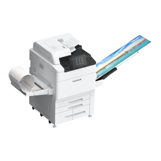
FujiFilm ApeosPro C810 Reference Manual
Main unit
Hide thumbs
Also See for ApeosPro C810:
- Reference manual (88 pages) ,
- User manual (12 pages) ,
- Reference manual (34 pages)

Related Manuals for FujiFilm ApeosPro C810


Summary of Contents for FujiFilm ApeosPro C810
- Page 1 ApeosPro™ C810 ApeosPro C750 ApeosPro C650 Reference Guide Main Unit April 2021 GM1036E1-1 Ver. 1 FUJIFILM Business Innovation Corp.
- Page 2 This product uses eT-Kernel. eT-Kernel is a trademark of eSOL Co., Ltd. in Japan and other countries. Other company names or product names are registered trademarks or trademarks of each company. FUJIFILM and FUJIFILM logo are registered trademarks or trademarks of FUJIFILM Corporation. ApeosPro, ApeosWiz, DocuWorks, PaperSecurity, Smart WelcomEyes and TrustMarkingBasic are registered trademarks or trademarks of FUJIFILM Business Innovation Corp.
- Page 3 Notations in Manual The following symbols are used in this manual. Information that you must know and information that you should confirm before Important operation. Reference information for operation. Note Reference pages. Refer “ ” Names and inputs of folders, files, apps, and functions. Also reference pages of the manual.
-
Page 4: Before Using The Machine
Before Using the Machine Device Components Front Component Function Document Cover Holds a document in place. Document Glass Load a document here. Control Panel Consists of operation buttons, LED indicators, and the Touch Panel Display. Smart WelcomEyes(SWE) Motion Exits the Power Saver Mode when the machine detects Sensor user presence. - Page 5 Component Function Waste Toner Container Cover Open this cover to replace the Waste Toner Container. Paper Trays 1, 2, 3, 4 Load paper here. Locking casters Used to move this machine. Lower Left Cover Open this cover to clear paper jams. Paper Tray 5 (Bypass) Used for loading non-standard paper that cannot be loaded in Trays 1, 2, 3, 4.
-
Page 6: Lan Connection
Component Function Wireless Network Kit Used for connecting wireless network (Wi-Fi/Bluetooth) to the (optional) machine. Reset button Automatically switches the machine off when a current leakage is detected. LAN connection When connecting to the network port, keep the machine power switched off. Note When a connection failure occurs, it may be improved by setting [Disabled] in >... - Page 7 Component Function Fusing Unit Fuses toner on paper. Note Do not touch this unit as it is extremely hot. Handle Used to pull out the Transfer Unit. Transfer Unit Transfers toner images on the drum to paper. Cleaning Bar Clean the LED printheads. Lock Release Handle Release the lock to replace Toner Cartridges.
-
Page 8: Control Panel
Control Panel Refer For Control Panel, refer to the Reference Guide - Operations. Component Function Built-in IC Card Used to authenticate a user using an IC card. Reader (optional) Paper Clip Tray Used for placing paper clips and staples. Power Button The power switches on. -
Page 9: Print Area
Component Function USB memory slot Insert a USB memory device directly here. (optional) Note A memory card reader or a USB memory device cannot be connected to the USB memory slot with a USB cable. Note that the machine will not recognize the memory on a memory card reader or a memory device connected to a USB interface connector on the rear side of the machine when a USB memory device is already inserted in the USB memory slot. - Page 10 Larger than A3 Copying 297 x 432 max. Printing 317 x 480 max. Standard Printable Area (mm) A3 or smaller Area excluding a margin (4.1 mm) along all four edges of the paper. Larger than A3 Standard size 317 x 480 max. Custom Size Area excluding a margin (4.1 mm) along all four edges of the paper.
-
Page 11: Recommended Paper
Paper Recommended Paper Standard paper Paper name Paper type setting for paper Image quality Paper weight tray guarantee (g/m Uncoated Monochrome paper J paper Uncoated Color To use paper other than the above, contact our customer support center or sales agency. Recycled paper Paper name Paper type setting for... -
Page 12: Handling Paper
Handling paper Do not use collected pieces of paper. Do not use wrinkled or folded paper. Do not load paper of different sizes or types in the same tray. Before loading paper into the tray, fan a stack of paper well to prevent paper jams and double- feeding (multiple sheets of paper are being fed simultaneously) of transparency films, films and coated paper. -
Page 13: Loading Paper
Basic Operations of the Machine Loading Paper After loading paper, configure the Paper Tray settings on the Home screen. Important Do not place paper or other objects in the reserved space of the tray. It may cause paper jams or machine malfunction. - Page 14 When loading paper whose size is JIS B4 or larger, pinch the knob and lift the paper rear end guide, and set the guide into the hole for the indicated size. Pinch the two Guide Clips, and adjust to the correct paper size.
-
Page 15: Bypass Tray
The bottom face of loaded paper is the surface printed on. Loadable paper Paper size JIS B5, A4, Letter Single side 52 to 300 Paper weight (g/m printing Maximum number of sheets Tray 3 (sheets) (J paper) Tray 4 1,280 Pull out the Paper Tray until it stops. - Page 16 Loadable paper Paper size (mm) Standard Max: A3, 11 x 17", Min: Postcard (by size Japan Post) 100 x 148 mm to 330 x 488 mm Custom size (long paper: more than 488 to 1,300) Paper weight Single side 52 to 350 (long paper: 52 to 220) printing (g/m Maximum number of sheets...
- Page 17 Paper orientation when the flaps are closed: Flaps come at the right when viewed from the front of the machine Note Load envelopes with glue or seal as the flap is closed. The loadable envelope size is up to 428 mm for the length. Long paper Load paper one sheet at a time.
-
Page 18: Loading Documents
Adjust the Paper Guide to the correct paper size. Loading Documents Document Feeder Loadable paper Paper size A3, 11 x 17" Custom size 84 x 140 mm to 297 x 432 mm Paper weight Single side printing 38 to 200 (g/m Double side printing 50 to 200... -
Page 19: Document Glass
When the confirmation indicator lights up, move the document guide to align with both edges of the document. Open the Document Stopper. Note To prevent a document from being left behind, “Document Feeder Attention Light” is turned on from the beginning until the completion of a Scan job. -
Page 20: Outputting Paper
Outputting Paper Print Surface The print surface refers to the surface printed on in single-sided printing (the first page in double- sided printing). Paper is output to the Tray with the print surface faced downward. Note Paper cannot be output upside down. Single-sided printing Double-sided printing Paper size (mm) - Page 21 - Single-sided prints / double-sided prints - Image density Extension Tray Insert 2 extension trays until they stop. Note Pass them through over the guide at the rear side of the tray until they stop. Thin paper loading wire When it is difficult to load thin paper, install the wire. Note ...
- Page 22 The paper is output with offset stacking for easy separation. Use the printer driver to set the offset of outputs. Paper size (mm) Width 170 to 297 Length 148 to 488 52 to 350 Paper weight (g/m Catch Tray Fan The catch tray fan is equipped with a knob to adjust the airflow volume.
-
Page 23: Maintenance
Maintenance Consumables Consumables recommended by our company are manufactured under the standards suitable for this machine. Using consumables not recommended by our company may affect print quality or performance provided by the product. Use consumables that our company recommends for this machine. -
Page 24: Led Printhead
Do not take out or shake the Waste Toner Container before it is filled up. Accurate detection can become no longer possible, and the toner may be spilled from the Waste Toner Container. When replacing the Waste Toner Container, toner may spill and soil the floor. We recommend laying a ... - Page 25 Scanner Document cover, Document Glass, film, scanner glass Wipe off any dirt with the supplied cloth about once a month. When stains cannot be removed easily, wipe them lightly with the soft cloth slightly moistened with a thin neutral detergent solution.
-
Page 26: Paper Jams
While turning the rollers, wipe them with a soft cloth slightly moistened with water. Close the Top Cover of the Document Feeder and make sure that there is no gap on the front or rear of the cover. Paper Jams If paper is jammed, the machine stops and an alarm sounds. -
Page 27: Right Side
Right side Open the Lower Right Cover. Remove the jammed paper. Close the Lower Right Cover. Exit Depending on the optional units equipped in the right side of the machine, the method of paper removal differs. Refer For optional units, refer to Reference Guide - Optional Units. Paper Trays 1, 2 Pull out the Paper Tray where the paper jam occurred until it stops. -
Page 28: Duplex Automatic Document Feeder
Paper Trays 3, 4 Pull out the Paper Tray where the paper jam occurred until it stops. Remove the jammed paper. Pull out the Tray 3 and Tray 4. Pull out the unit [C], then open the handle and remove the jammed paper. -
Page 29: Transfer Unit
Pull up the front handle of the Top Cover and open the cover until it stops. Open the Left Cover until it stops. Left cover Remove the document. If the document is caught in the entry, remove the jammed paper from the Left Cover. If the document is caught in the exit area, lift the Document Feeder Tray and pull the document toward the exit. - Page 30 Warning The Fusing Unit is hot. It may cause burn injury. Do not touch this unit. Open the Front Cover. Turn the handle [2] of the Transfer Unit to the right until it becomes horizontal ( ) and pull the Transfer Unit out to the front until it stops ( Slowly pull out the paper in the arrow direction and remove Note...
- Page 31 [2d] Open the handle [2d] down and remove the jammed paper. Return the handle [2d]. Push the Transfer Unit to the rearmost position and turn the handle [2] to the left. Close the Front Cover. Long paper When paper remains on bypass tray of Large Capacity Tray Open the Upper Cover of the bypass tray and remove the jammed paper.
- Page 32 Open the handle [1d] upward. Turn the knob [1c] to the right and remove the jammed paper (lead edge). When paper is jammed in delivery unit Note When long paper is jammed, the error indicator and/or message displayed on the details screen may be different from the actual jam state.
-
Page 33: Main Specifications
Appendix Main Specifications This section lists the main specifications of the machine. Note that the specifications and the appearance of the product may change without prior notice. Note The specifications are not intended to guarantee the image quality performance and feeding performance of all papers. - Page 34 Item Specification Continuous print speed Paper size (pages/minute) C810 C750 C650 Note When continuous single side printing of same document, 52 to 128 g/m (color), 52 to 176 g/m (monochrome), uncoated. The continuous print speed may be lowered according to the data output conditions, auto adjustment of image quality, job with mixed paper sizes and/or paper types, switch of the paper feed tray, and paper output for long paper.
- Page 35 Item Specification Installation space (mm) Width 1,759 x Depth 1,791 Note Required installation space (of the minimum configuration) when the Catch Tray is installed to the main unit and the Bypass Tray is fully extended. Copying Function Item Specification Scan 600 x 600 dpi resolution Printing...
- Page 36 Item Specification Transmission time 2 seconds or more but below 3 seconds Note When transmitting an A4 size 700-character document in the standard quality (8 x 3.85 lines/mm) and high speed mode (28.8 kbps or above: JBIG). This is only the transmission speed for image information and does not include the controlling time for the communication.
- Page 37 Item Specification Interface Ethernet 1000BASE-T/100BASE-TX/10BASE-T IP fax (SIP) Item Specification Document size Same as the Fax Function Scanning resolution Same as the Fax Function Supported protocol SIP, JT-T.38 Coding method Same as the Fax Function Interface Ethernet 1000BASE-T/100BASE-TX/10BASE-T Duplex Automatic Document Feeder Item Specification Type...
-
Page 38: Safety Notes
Safety Notes Refer Also refer to User's Manual. Location of Warning and Caution Labels 必ずアース接続を 行ってください。 この装置は複数の電源コード を使用しています。 装置の電源供給を停止するた めには、すべての電源プラグ を抜く必要があります。 定格電圧 100V 定格電流 定格周波数 50/60Hz Reference Guide Main Unit... - Page 39 5 Appendix...
- Page 40 The locations of the labels for Finisher are explained using an illustration in which the Folder Unit is installed to Finisher C as an example. Reference Guide Main Unit...
- Page 41 5 Appendix...
- Page 42 Symbols Marked on the Machine DANGER, DO NOT USE DO NOT THROW A CAUTION, AND ENVELOPE TONER WARNING CARTRIDGE INTO AN OPEN FLAME CAUTION DO NOT USE DO NOT THROW (HEATED POSTCARDS WASTE TONER SURFACE) CONTAINER INTO AN OPEN FLAME DO NOT INSERT A DO NOT USE DO NOT THROW...