
Related Manuals for Siemens RUGGEDCOM RX1100


Summary of Contents for Siemens RUGGEDCOM RX1100
- Page 1 Preface Introduction Installing the Device RUGGEDCOM RX1100 Communication Ports Technical Specifications Dimension Drawings Installation Guide Certification 4/2015 RC1051-EN-03...
- Page 2 Warranty Siemens warrants this product for a period of five (5) years from the date of purchase, conditional upon the return to factory for maintenance during the warranty term. This product contains no user-serviceable parts. Attempted service by unauthorized personnel shall render all warranties null and void.
-
Page 3: Table Of Contents
RUGGEDCOM RX1100 Installation Guide Table of Contents Table of Contents Preface ........................ Alerts ..............................v Related Documents ..........................v Accessing Documentation ........................v Training .............................. vi Customer Support ..........................vi Chapter 1 Introduction ......................1.1 Feature Highlights ........................1 1.2 Ports, Controls and Indicator LEDs ....................3 Chapter 2 Installing the Device .................... - Page 4 RUGGEDCOM RX1100 Table of Contents Installation Guide 3.7 Serial Ports ..........................21 3.8 Precision Time Protocol (PTP) Ports ................... 23 3.8.1 IRIG-B Outputs ........................ 24 3.8.2 Pulse-Per-Second (PPS) Output ..................24 3.8.3 GPS Antenna Installation Recommendations ..............25 3.8.3.1 GPS Antenna ....................... 25 3.8.3.2 Antenna Cabling ....................
-
Page 5: Preface
Installation Guide Preface Preface This guide describes the RUGGEDCOM RX1100. It describes the major features of the device, installation, commissioning and important technical specifications. It is intended for use by network technical support personnel who are responsible for the installation, commissioning and maintenance of the device. -
Page 6: Training
Siemens sales representative. Customer Support Customer support is available 24 hours, 7 days a week for all Siemens customers. For technical support or general information, contact Siemens Customer Support through any of the following methods: • Online Visit http://www.siemens.com/automation/support-request... -
Page 7: Introduction
RUGGEDCOM RX1100 Chapter 1 Installation Guide Introduction Introduction The RX1100 is an industrially hardened cyber security appliance with integrated router, firewall and VPN functionality. The device may be equipped with up to four 10/100Base-TX 802.3af (PoE) copmliant Ethernet ports. The RX1100 can be used to establish an electronic security perimeter around critical cyber assets found in control and automation systems, in order to prevent the disruption of operations by accidental or malicious acts. - Page 8 Chapter 1 RUGGEDCOM RX1100 Introduction Installation Guide ▪ Exceeds NEMA TS-2 (traffic control equipment) • -40 to 85 °C (-40 to 185 °F) operating temperature (no fans) • Failsafe output relay: for crtical failure or error alarming • 18 AWG galvanized steel enclosure and 48 cm (19 in) rack-mount adapter Universal Power Supply Options •...
-
Page 9: Ports, Controls And Indicator Leds
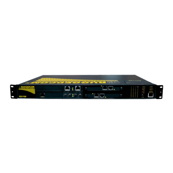
RUGGEDCOM RX1100 Chapter 1 Installation Guide Introduction Section 1.2 Ports, Controls and Indicator LEDs The RX1100 features various ports, controls and indicator LEDs on the front panel for configuring and troubleshooting the device. Figure 1: Front Panel 1. Port Status Indicator LEDs 2. - Page 10 RUGGEDCOM RX1100 Chapter 1 Installation Guide Introduction Ports, Controls and Indicator LEDs...
-
Page 11: Installing The Device
This product contains no user-serviceable parts. Attempted service by unauthorized personnel shall render all warranties null and void. Changes or modifications not expressly approved by Siemens Canada Ltd. could invalidate specifications, test results, and agency approvals, and void the user's authority to operate the equipment. -
Page 12: Mounting The Device To A Rack
Chapter 2 RUGGEDCOM RX1100 Installing the Device Installation Guide NOTE For detailed dimensions of the device with either rack, DIN rail or panel hardware installed, refer to Chapter 5, Dimension Drawings. The following sections describe the various methods of mounting the device: •... -
Page 13: Mounting The Device On A Din Rail
RUGGEDCOM RX1100 Chapter 2 Installation Guide Installing the Device Section 2.1.2 Mounting the Device on a DIN Rail For DIN rail installations, the RX1100 can be equipped with panel/DIN rail adapters pre-installed on each side of the chassis. The adapters allow the device to be slid onto a standard 35 mm (1.4 in) DIN rail. -
Page 14: Connecting Power
Chapter 2 RUGGEDCOM RX1100 Installing the Device Installation Guide Figure 4: Panel Mounting 1. Screw 2. Panel/DIN Rail Adaptor Install the supplied screws to secure the adapters to the panel. Section 2.2 Connecting Power The RX1100 can be equipped with either a screw-type or pluggable terminal block, which provides power to both power supplies. -
Page 15: Connecting Ac Power
RUGGEDCOM RX1100 Chapter 2 Installation Guide Installing the Device The following sections describe how to connect power to the device: • Section 2.2.1, “Connecting AC Power” • Section 2.2.2, “Connecting DC Power” • Section 2.2.3, “Wiring Examples” Section 2.2.1 Connecting AC Power... -
Page 16: Connecting Dc Power
Chapter 2 RUGGEDCOM RX1100 Installing the Device Installation Guide Figure 5: Terminal Block Wiring 1. Screw-Type Terminal Block 2. Pluggable Terminal Block 3. Jumper 4. Positive/Live (+/L) Terminal 5. Negative/Neutral (-/N) Terminal 6. Surge Ground Terminal 7. Chassis Ground Terminal Connect the negative wire from the power source to the negative/neutral (-/N) terminal on the terminal block. - Page 17 RUGGEDCOM RX1100 Chapter 2 Installation Guide Installing the Device NOTE The screw-type terminal block is installed using Philips screws and compression plates, allowing either bare wire connections or crimped terminal lugs. Use #6 size ring lugs for secure, reliable screws, which must be removed to make connections.
-
Page 18: Wiring Examples
Chapter 2 RUGGEDCOM RX1100 Installing the Device Installation Guide Section 2.2.3 Wiring Examples The following illustrate how to connect power to single and dual power supplies. Figure 7: Single AC Power Supply Figure 8: Single DC Power Supply Wiring Examples... - Page 19 RUGGEDCOM RX1100 Chapter 2 Installation Guide Installing the Device Figure 9: Dual AC Power Supply Figure 10: Dual DC Power Supply Wiring Examples...
-
Page 20: Connecting The Failsafe Alarm Relay
Chapter 2 RUGGEDCOM RX1100 Installing the Device Installation Guide Figure 11: Dual AC/DC Power Supply Section 2.3 Connecting the Failsafe Alarm Relay The failsafe relay can be configured to latch based on alarm conditions. The NO (Normally Open) contact is closed when the unit is powered and there are no active alarms. -
Page 21: Grounding The Device
Section 2.5 Cabling Recommendations Siemens does not recommend the use of copper cabling of any length for critical, real-time substation automation applications. All copper Ethernet ports on RUGGEDCOM products include transient suppression circuitry to protect against damage from electrical transients and conform with IEC 61850-3 and IEEE 1613 Class 1 standards. -
Page 22: Connecting To The Device
Installing the Device Installation Guide Siemens also does not recommend using copper Ethernet ports to interface with devices in the field across distances that could produce high levels of ground potential rise (i.e. greater than 2500 V), during line-to-ground fault conditions. -
Page 23: Communication Ports
RUGGEDCOM RX1100 Chapter 3 Installation Guide Communication Ports Communication Ports The RX1100 can be equipped with various types of communication ports to enhance its abilities and performance. To determine which ports are equipped on the device, refer to the factory data file available through ROX . -
Page 24: Copper Ethernet Ports
Chapter 3 RUGGEDCOM RX1100 Communication Ports Installation Guide • Section 3.4, “DSL Ports” • Section 3.5, “DDS Ports” • Section 3.6, “Modem Port” • Section 3.7, “Serial Ports” • Section 3.8, “Precision Time Protocol (PTP) Ports” • Section 3.9, “RS232 External Modem Ports”... -
Page 25: Fiber Optic Ethernet Ports
RUGGEDCOM RX1100 Chapter 3 Installation Guide Communication Ports Section 3.2 Fiber Optic Ethernet Ports Fiber optic Ethernet ports are available with either MTRJ (Mechanical Transfer Registered Jack), LC (Lucent Connector), SC (Standard or Subscriber Connector) or ST (Straight Tip) connectors. Make sure the Transmit (Tx) and Receive (Rx) connections of each port are properly connected and matched to establish a proper link. -
Page 26: Dsl Ports
Chapter 3 RUGGEDCOM RX1100 Communication Ports Installation Guide Section 3.4 DSL Ports The RX1100 can optionally be equipped with a dual-port DSL (Digital Subscriber Line) card, which can communicate over standard telephone communication lines. The DSL card supports the following modulation standards: •... -
Page 27: Modem Port
RUGGEDCOM RX1100 Chapter 3 Installation Guide Communication Ports Section 3.6 Modem Port The RX1100 can optionally be equipped with a V.90 Modem connection for PPP (Point-to-Point Protocol) connections. For information about how to configure and operate the modem, refer to the ROX User Guide for the RX1100. - Page 28 Chapter 3 RUGGEDCOM RX1100 Communication Ports Installation Guide State Description Green Link activity detected No link detected For specifications on serial ports, refer to Section 4.5, “Serial Port Specifications”. The following is the pin-out description for DB25 and RJ45 serial ports:...
-
Page 29: Precision Time Protocol (Ptp) Ports
RUGGEDCOM RX1100 Chapter 3 Installation Guide Communication Ports RS232 Mode RS485 Mode RS422 Mode DSR/RI Common (Isolated) Ground Figure 26: Serial RJ45 Port Pin Configuration TX/RX+ TX/RX- Shield Chassis Ground Connected internally. In RS232 mode, this pin enters a high impedance state. A DTE that asserts RTS will see CTS asserted, although the device will not perform hardware flow control. -
Page 30: Irig-B Outputs
Chapter 3 RUGGEDCOM RX1100 Communication Ports Installation Guide The following sections describe the PTP card in more detail: • Section 3.8.1, “IRIG-B Outputs” • Section 3.8.2, “Pulse-Per-Second (PPS) Output” • Section 3.8.3, “GPS Antenna Installation Recommendations” Section 3.8.1 IRIG-B Outputs The PTP Card supports both IRIG-B outputs in both Amplitude Modulated (AM) and Pulse Width Modulation (PWM) formats. -
Page 31: Gps Antenna Installation Recommendations
RUGGEDCOM RX1100 Chapter 3 Installation Guide Communication Ports Section 3.8.3 GPS Antenna Installation Recommendations The signals received from the GPS satellite network are at a frequency of 1575.42 MHz with a minimum power of -162 dBW. The GPS antenna must have a clear view of the sky in order to receive the low power signals and track the maximum number of satellites. -
Page 32: Antenna Cabling
The time delay is dependent on the type of dielectric material in the cable and ranges from 1 to 2 ns/ft. Siemens provides a method to account for this delay through the web management interface by entering the time delay into the cable compensation box under PTP General Configuration. -
Page 33: Rs232 External Modem Ports
RUGGEDCOM RX1100 Chapter 3 Installation Guide Communication Ports Most active antennas include filters. However, if there is a high potential for electromagnetic interference, such as from the near field of a radio transmitter, though the antenna system, additional antenna line filtering may be necessary. -
Page 34: Evdo Cellular Modem
Chapter 3 RUGGEDCOM RX1100 Communication Ports Installation Guide • Section 3.10.1, “EVDO Cellular Modem” • Section 3.10.2, “HSPA (GSM) Cellular Modem” • Section 3.10.3, “GSM/EDGE Internal Cellular Modem” Section 3.10.1 EVDO Cellular Modem The EVDO dual band card option is offered for use on Verizon's cellular network. The radio supports IS-95A, 1xRTT, 1xEVDO Rev0 and 1xEVDO RevA, and will automatically select the fastest mode available when a data call is made. - Page 35 RUGGEDCOM RX1100 Chapter 3 Installation Guide Communication Ports Figure 31: HSPA Cellular Modem 1. Receive Diversity Antenna SMA Connector 2. Access Panel 3. Main Antenna SMA Connector Installing a SIM Card SIM card access is available on the front faceplate of the HSPA module. Follow these steps to install a SIM card: Disconnect power from the device.
-
Page 36: Gsm/Edge Internal Cellular Modem
Chapter 3 RUGGEDCOM RX1100 Communication Ports Installation Guide Section 3.10.3 GSM/EDGE Internal Cellular Modem The GSM/EDGE internal cellular modem option is available for use on various GSM-based networks. The card supports GSM and EDGE. The single antenna connection is made to the 50 Ω SMA connector located on the front faceplate. -
Page 37: Connecting Multiple Rs485 Devices
RUGGEDCOM RX1100 Chapter 3 Installation Guide Communication Ports Section 3.11 Connecting Multiple RS485 Devices Each RS485 port can communicate with multiple RS485 devices by wiring devices together in sequence over a single twisted pair with transmit and receive signals on the same two wires (half duplex). For reliable, continuous communication, adhere to the following guidelines: •... - Page 38 RUGGEDCOM RX1100 Chapter 3 Installation Guide Communication Ports Connecting Multiple RS485 Devices...
-
Page 39: Technical Specifications
RUGGEDCOM RX1100 Chapter 4 Installation Guide Technical Specifications Technical Specifications The following sections provide important technical specifications related to the device and available modules: • Section 4.1, “Power Supply Specifications” • Section 4.2, “Failsafe Relay Specifications” • Section 4.3, “Copper Ethernet Port Specifications”... -
Page 40: Copper Ethernet Port Specifications
To convert from peak to average, subtract 3 dBm. • Maximum segment length is greatly dependent on factors such as fiber quality, and the number of patches and splices. Consult a Siemens sales associate when determining maximum segment distances. Power... -
Page 41: Serial Port Specifications
RUGGEDCOM RX1100 Chapter 4 Installation Guide Technical Specifications Power Connector Cable Tx λ (typ.) Tx min. Tx max. Distance Mode Sensitivity Saturation Budget Type Type (μm) (nm) (dBm) (dBm) (typ.) (km) (dBm) (dBm) (dB) 9/125 1300 9/125 1300 9/125 1300... -
Page 42: Mechanical Specifications
Chapter 4 RUGGEDCOM RX1100 Technical Specifications Installation Guide Section 4.8 Mechanical Specifications Parameter Value Dimensions Refer to Chapter 5, Dimension Drawings Weight 10 lb (4.5 Kg) Ingress Protection IP40 Enclosure 18 AWG galvanized steel Mechanical Specifications... -
Page 43: Dimension Drawings
RUGGEDCOM RX1100 Chapter 5 Installation Guide Dimension Drawings Dimension Drawings NOTE All dimensions are in millimeters, unless otherwise stated. 437.4 44.5 Figure 34: Overall Dimensions... - Page 44 Chapter 5 RUGGEDCOM RX1100 Dimension Drawings Installation Guide 479.3 461.0 21.1 32.5 Figure 35: Rack Mount Dimensions...
- Page 45 RUGGEDCOM RX1100 Chapter 5 Installation Guide Dimension Drawings 486.4 476.3 438.2 Figure 36: Panel and DIN Rail Mount Dimensions...
- Page 46 RUGGEDCOM RX1100 Chapter 5 Installation Guide Dimension Drawings...
-
Page 47: Certification
RUGGEDCOM RX1100 Chapter 6 Installation Guide Certification Certification The RX1100 device has been thoroughly tested to guarantee its conformance with recognized standards and has received approval from recognized regulatory agencies. • Section 6.1, “Agency Approvals” • Section 6.2, “FCC Compliance”... -
Page 48: Emi And Environmental Type Tests
Chapter 6 RUGGEDCOM RX1100 Certification Installation Guide Section 6.4 EMI and Environmental Type Tests The RX1100 has passed the following EMI and environmental tests. IEC 61850-3 EMI Type Tests NOTE • In the case of an all fiber port configuration, this product meets all Class 2 requirements. Otherwise, all Class 1 requirements are met for copper ports. - Page 49 RUGGEDCOM RX1100 Chapter 6 Installation Guide Certification Test Description Test Levels Severity Levels IEC 61000-4-12 Damped Oscillatory Signal ports 2.5 kV common, 1 kV differential mode @ 1 MHz DC Power ports 2.5kV common,1kV differential mode @ 1 MHz AC Power ports 2.5 kV common,...
-
Page 50: Cellular Modem Certifications
Chapter 6 RUGGEDCOM RX1100 Certification Installation Guide Test Description Test Levels AC Power ports 2.5 kV common and differential mode @ 1 MHz IEEE C37.90 HV Impulse Signal ports 5 kV (Failsafe Relay) DC Power ports 5 kV AC Power ports 5 kV IEEE C37.90...