Siemens RUGGEDCOM RS416 Installation Manual
Hide thumbs
Also See for RUGGEDCOM RS416:
- Installation manual (42 pages) ,
- Installation manual (52 pages)

Related Manuals for Siemens RUGGEDCOM RS416


Summary of Contents for Siemens RUGGEDCOM RS416
- Page 1 Preface Introduction Installing Device RUGGEDCOM RS416 Communication Ports Technical Specifications Dimension Drawings Installation Guide Certification 06/2016 RC1018-EN-04...
-
Page 2: Security Information
Warranty Siemens warrants this product for a period of five (5) years from the date of purchase, conditional upon the return to factory for maintenance during the warranty term. This product contains no user-serviceable parts. Attempted service by unauthorized personnel shall render all warranties null and void. - Page 3 RUGGEDCOM RS416 Installation Guide Contacting Siemens Address Telephone E-mail ruggedcom.info.i-ia@siemens.com Siemens Canada Ltd. Toll-free: 1 888 264 0006 Industry Sector Tel: +1 905 856 5288 www.siemens.com/ruggedcom 300 Applewood Crescent Fax: +1 905 856 1995 Concord, Ontario Canada, L4K 5C7...
- Page 4 RUGGEDCOM RS416 Installation Guide...
-
Page 5: Table Of Contents
RUGGEDCOM RS416 Installation Guide Table of Contents Table of Contents Preface ......................Alerts ..............................vii Related Documents ..........................vii Accessing Documentation ........................vii Training ............................viii Customer Support ..........................viii Chapter 1 Introduction ..................... 1.1 Feature Highlights ........................1 1.2 Description ........................... 2 1.3 Precision Time Protocol (PTP) Support .................... - Page 6 RUGGEDCOM RS416 Table of Contents Installation Guide 3.3 Serial Ports ..........................21 3.4 BNC Ports ........................... 24 3.5 Connecting Multiple RS485 Devices ..................... 25 Chapter 4 Technical Specifications .................. 4.1 Power Supply Specifications ......................27 4.2 Failsafe Relay Specifications ......................27 4.3 Copper Ethernet Port Specifications ....................
-
Page 7: Preface
Installation Guide Preface Preface This guide describes the RUGGEDCOM RS416. It describes the major features of the device, installation, commissioning and important technical specifications. It is intended for use by network technical support personnel who are responsible for the installation, commissioning and maintenance of the device. -
Page 8: Training
Siemens Sales representative. Customer Support Customer support is available 24 hours, 7 days a week for all Siemens customers. For technical support or general information, contact Siemens Customer Support through any of the following methods: Online Visit http://www.siemens.com/automation/support-request... -
Page 9: Introduction
Introduction Introduction The RUGGEDCOM RS416 is an industrially hardened serial device server with an integrated, fully managed, Ethernet switch, designed to operate reliably in electrically harsh and climatically demanding environments. Featuring a modular design that can support IEEE 1588 and IRIG-B time synchronization, up to 16 serial ports and up to four Ethernet ports, the RS416 is able to interconnect and synchronize multiple types of intelligent electronic devices (IEDs). -
Page 10: Description
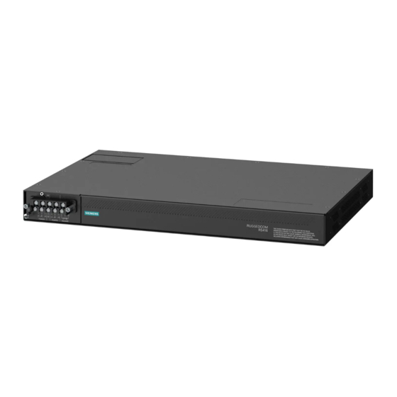
Chapter 1 RUGGEDCOM RS416 Introduction Installation Guide Ethernet Ports • Integrated Ethernet switch • Copper or fiber options • Supports IEEE 1588 v2 • Non-blocking, store and forward switching IRIG-B Option • Conversion from IEEE 1588 v2 • One IRIG-B PWM/PPS Output •... - Page 11 Chapter 1 Installation Guide Introduction Figure 1: RUGGEDCOM RS416 1. Serial Ports 2. Fiber Optic Ethernet and/or BNC (Optional) Ports 3. Port Status Indicator LEDs 4. Display Mode Indicator LEDs 5. Mode Button 6. Alarm Indicator LED 7. Power Module Indicator LEDs 8. RS-232 Serial Console Port (RJ45) • Communication Ports – Ports for communicating with other devices or accessing the RUGGEDCOM ROS operating system are described in Chapter 3, Communication...
-
Page 12: Precision Time Protocol (Ptp) Support
Chapter 1 RUGGEDCOM RS416 Introduction Installation Guide Section 1.3 Precision Time Protocol (PTP) Support The Precision Time Protocol (PTP) module adds the ability to provide time synchronization via Ethernet using the Precision Time Protocol (PTP) and Network Time Protocol (NTP), and to synchronize with an external IRIG-B source. -
Page 13: Ttl Outputs
RUGGEDCOM RS416 Chapter 1 Installation Guide Introduction IRIG-B PWM IRIG-B time synchronization is an even older, established, inter-device time synchronization mechanism providing accuracy in sub-milliseconds. IEEE 1588 IEEE 1588 is designed to provide networked, packet-based time synchronization between different networking nodes (PTP devices). -
Page 14: Ieee 1588 Support
Introduction Installation Guide Section 1.3.3 IEEE 1588 Support RUGGEDCOM RS416 supports various IEEE 1588 time synchronization capabilities and provides synchronization in 2-step mode. This mode supports the following clock types: • End-to-End Slave Clock • End-to-End Master Clock • Peer-to-Peer Slave Clock •... -
Page 15: Installing Device
This product contains no user-serviceable parts. Attempted service by unauthorized personnel shall render all warranties null and void. Changes or modifications not expressly approved by Siemens Canada Ltd. could invalidate specifications, test results, and agency approvals, and void the user's authority to operate the equipment. -
Page 16: Mounting The Device To A Rack
Chapter 2 RUGGEDCOM RS416 Installing Device Installation Guide NOTE For detailed dimensions of the device with either rack, DIN rail or panel hardware installed, refer to Chapter 5, Dimension Drawings. CONTENTS • Section 2.1.1, “Mounting the Device to a Rack” • Section 2.1.2, “Mounting the Device on a DIN Rail”... -
Page 17: Mounting The Device On A Din Rail
RUGGEDCOM RS416 Chapter 2 Installation Guide Installing Device Forced airflow is not required. However, any increase in airflow will result in a reduction of ambient temperature and improve the long-term reliability of all equipment mounted in the rack space. Secure the adapters to the rack using the supplied hardware. -
Page 18: Connecting Power
Chapter 2 RUGGEDCOM RS416 Installing Device Installation Guide Figure 6: Panel Mounting 1. Screw 2. Panel/DIN Rail Adaptor Install the supplied screws to secure the adapters to the panel. Section 2.2 Connecting Power The RS416 supports single or dual redundant high AC and/or low DC power supplies. The use of two power modules is recommended to provide redundancy and load balancing. -
Page 19: Connecting Ac Power
RUGGEDCOM RS416 Chapter 2 Installation Guide Installing Device • It is recommended to provide a separate circuit breaker for each power supply module. • Equipment must be installed according to applicable local wiring codes and standards. CONTENTS • Section 2.2.1, “Connecting AC Power”... -
Page 20: Connecting Dc Power
Chapter 2 RUGGEDCOM RS416 Installing Device Installation Guide Figure 7: Terminal Block Wiring 1. Screw-Type Terminal Block 2. Pluggable Terminal Block 3. Jumper 4. Positive/Live (+/L) Terminal 5. Negative/Neutral (-/N) Terminal (-/N) 6. Surge Ground Terminal 7. Chassis Ground Terminal Connect the negative wire from the power source to the negative/neutral (-/N) terminal on the terminal block. - Page 21 RUGGEDCOM RS416 Chapter 2 Installation Guide Installing Device NOTE The screw-type terminal block is installed using Philips screws and compression plates, allowing either bare wire connections or crimped terminal lugs. Use #6 size ring lugs for secure, reliable screws, which must be removed to make connections.
-
Page 22: Wiring Examples
Chapter 2 RUGGEDCOM RS416 Installing Device Installation Guide Section 2.2.3 Wiring Examples The following illustrate how to connect power to single and dual power supplies. Figure 9: Single AC Power Supply Figure 10: Single DC Power Supply Wiring Examples... - Page 23 RUGGEDCOM RS416 Chapter 2 Installation Guide Installing Device Figure 11: Dual AC Power Supply Figure 12: Dual DC Power Supply Wiring Examples...
-
Page 24: Connecting The Failsafe Alarm Relay
Chapter 2 RUGGEDCOM RS416 Installing Device Installation Guide Figure 13: Dual AC/DC Power Supply Section 2.3 Connecting the Failsafe Alarm Relay The failsafe relay can be configured to latch based on alarm conditions. The NO (Normally Open) contact is closed when the unit is powered and there are no active alarms. If the device is not powered or if an active alarm is configured, the relay opens the NO contact and closes the NC (Normally Closed) contact. -
Page 25: Grounding The Device
RUGGEDCOM RS416 Chapter 2 Installation Guide Installing Device Figure 14: Failsafe Alarm Relay Wiring 1. Screw-Type Terminal Block 2. Pluggable Terminal Block 3. Normally Open Terminal 4. Common Terminal 5. Normally Closed Terminal Section 2.4 Grounding the Device The RS416 chassis ground terminal uses a #6-32 screw. It is recommended to terminate the ground connection with a #6 ring lug and torque it to 1.7 N·m (15 lbf·in). -
Page 26: Cabling Recommendations
Siemens also does not recommend using copper Ethernet ports to interface with devices in the field across distances that could produce high levels of ground potential rise (i.e. greater than 2500 V), during line-to-ground fault conditions. -
Page 27: Communication Ports
Chapter 3 Installation Guide Communication Ports Communication Ports The RUGGEDCOM RS416 can be equipped with various types of communication ports to enhance its abilities and performance. Each communication port type has a specific place in the RUGGEDCOM RS416 chassis. Figure 17: Port Assignment 1. Slot 1 ... -
Page 28: Fiber Optic Ethernet Ports
Chapter 3 RUGGEDCOM RS416 Communication Ports Installation Guide RJ45 receptacles at either end. Ground loops can cause excessive noise and interference, but more importantly, create a potential shock hazard that can result in serious injury. LEDs Each port features LEDs that indicate the state of the port. -
Page 29: Serial Ports
RUGGEDCOM RS416 Chapter 3 Installation Guide Communication Ports Figure 21: LC Port Figure 20: MTRJ Port 1. Tx Connector 2. Rx Connector 1. Tx Connector 2. Rx Connector Figure 22: SC Port Figure 23: ST Port 1. Tx Connector 2. Rx Connector 1. Tx Connector 2. Rx Connector For specifications on the available fiber optic Ethernet ports, refer to Section 4.4, “Fiber Optic Ethernet Port... - Page 30 Chapter 3 RUGGEDCOM RS416 Communication Ports Installation Guide Fiber Serial Port Figure 24: ST Port 1. Tx Connector 2. Rx Connector Serial DB9 Port Mode RS232 DCE RS485 RS422 TX/RX+ Common (Isolated) Ground Figure 25: Serial DB9 Port Pin Configuration TX/RX- Shield Chassis Ground The DSR, DCD and DTR pins are connected together internally.
- Page 31 RUGGEDCOM RS416 Chapter 3 Installation Guide Communication Ports Serial DB9 Port with IRIG-B Support Mode RS232 DTE RS485 RS422 TX/RX+ IRIG-B+ Common (Isolated) Ground Common (Isolated) Ground Figure 26: Serial DB9 Port Pin Configuration TX/RX- Common (Isolated) Ground Shield Chassis Ground In RS232 DTE mode, ports transmit to DTE devices on pin 2 and receive from DTE on pin 3.
-
Page 32: Bnc Ports
Chapter 3 RUGGEDCOM RS416 Communication Ports Installation Guide Serial RJ45 Port with IRIG-B Support RS232 Mode RS485 Mode RS422 Mode +IRIG-B Common (Isolated) Ground Figure 28: Serial RJ45 Port Pin Configuration Common (Isolated) Ground TX/RX+ TX/RX- Shield Chassis Ground In RS232 mode, the RJ45 ports conform to EIA-561 DTE, which transmit on TXD and receive on RXD. -
Page 33: Connecting Multiple Rs485 Devices
• The twisted pair should be terminated at each end of the chain. The following shows the recommended RS485 wiring. 120Ω 10nF 120Ω 10nF Figure 30: Recommended RS485 Wiring 1. RUGGEDCOM RS416 2. Common (Isolated Ground) 3. Negative 4. Positive 5. Shield to Earth (Connected At a Single Point) 6. RS485 Devices (32 Total) Connecting Multiple RS485 Devices... - Page 34 RUGGEDCOM RS416 Chapter 3 Installation Guide Communication Ports Connecting Multiple RS485 Devices...
-
Page 35: Technical Specifications
RUGGEDCOM RS416 Chapter 4 Installation Guide Technical Specifications Technical Specifications This section provides important technical specifications related to the device and available modules. CONTENTS • Section 4.1, “Power Supply Specifications” • Section 4.2, “Failsafe Relay Specifications” • Section 4.3, “Copper Ethernet Port Specifications”... -
Page 36: Copper Ethernet Port Specifications
Chapter 4 RUGGEDCOM RS416 Technical Specifications Installation Guide Section 4.3 Copper Ethernet Port Specifications The following details the specifications for copper Ethernet ports that can be ordered with the RS416. Wiring Maximum Speed Connector Duplex Cable Type Isolation Standard Distance TIA/EIA... -
Page 37: Serial Port Specifications
RUGGEDCOM RS416 Chapter 4 Installation Guide Technical Specifications Power Connector Cable Tx Min. Tx Max. Distance Mode Tx λ (nm) Sensitivity Saturation Budget Type Type (μm) (dBm) (dBm) (km) (dBm) (dBm) (dB) 50/125 -22.5 62.5/125 1300 50/125 -22.5 62.5/125 MTRJ... -
Page 38: Fiber Serial Port Specifications
Chapter 4 RUGGEDCOM RS416 Technical Specifications Installation Guide Section 4.5.2 Fiber Serial Port Specifications Optical Mode Connector Typical Distance (km) Cable Size Wavelength (nm) 50/125 Multimode 62.5/125 Section 4.6 IRIG-B Port Specifications IRIG-B PWM Input Specifications Parameter Specification Input Voltage TTL-Compatible Input Impedance >... -
Page 39: Mechanical Specifications
RUGGEDCOM RS416 Chapter 4 Installation Guide Technical Specifications Section 4.8 Mechanical Specifications Parameter Value Dimensions Refer to Chapter 5, Dimension Drawings Weight 4.5 kg (10 lbs) Ingress Protection IP40 (1 mm or 0.04 in objects) Enclosure 18 AWG Galvanized Steel Mechanical Specifications... - Page 40 RUGGEDCOM RS416 Chapter 4 Installation Guide Technical Specifications Mechanical Specifications...
-
Page 41: Dimension Drawings
RUGGEDCOM RS416 Chapter 5 Installation Guide Dimension Drawings Dimension Drawings NOTE All dimensions are in millimeters, unless otherwise stated. 438.15 Figure 31: Overall Dimensions... - Page 42 Chapter 5 RUGGEDCOM RS416 Dimension Drawings Installation Guide 479.30 461.01 11.68 21.08 32.64 4.57 Figure 32: Rack Mount Dimensions...
- Page 43 RUGGEDCOM RS416 Chapter 5 Installation Guide Dimension Drawings 486.4 476.3 10.4 11.7 Figure 33: Panel and DIN Rail Mount Dimensions...
- Page 44 RUGGEDCOM RS416 Chapter 5 Installation Guide Dimension Drawings...
-
Page 45: Certification
RUGGEDCOM RS416 Chapter 6 Installation Guide Certification Certification The RUGGEDCOM RS416 device has been thoroughly tested to guarantee its conformance with recognized standards and has received approval from recognized regulatory agencies. CONTENTS • Section 6.1, “Approvals” • Section 6.2, “EMC and Environmental Type Tests”... -
Page 46: European Commission (Ec)
Safety of Laser Products – Equipment Classification and Requirements The device is marked with a CE symbol and can be used throughout the European community. A copy of the CE Declaration of Conformity is available from Siemens Canada Ltd.. For contact information, refer the section called “Contacting Siemens ”. -
Page 47: Industry Canada
Chapter 6 Installation Guide Certification Section 6.1.5 Industry Canada This device is declared by Siemens Canada Ltd. to meet the requirements of the following Industry Canada standard: • CAN ICES-3 (A)/NMB-3 (A) Section 6.1.6 Other Approvals This device meets the requirements of the following additional standards: •... - Page 48 5 kV (Fail-Safe Relay Output) DC Power ports 5 kV AC Power ports 5 kV Siemens specified severity level. IEEE 1613 EMC Immunity Type Tests NOTE The RS416 meets Class 2 requirements for an all-fiber configuration and Class 1 requirements for copper ports.
-
Page 49: Environmental Type Tests
RUGGEDCOM RS416 Chapter 6 Installation Guide Certification Description Test Levels Oscillatory Signal ports 2.5 kV common mode @ 1MHz DC Power ports 2.5 kV common and differential mode @ 1MHz AC Power ports 2.5 kV common and differential mode @ 1MHz... - Page 50 RUGGEDCOM RS416 Chapter 6 Installation Guide Certification EMC and Environmental Type Tests...