Table of Contents
Advertisement
Advertisement
Table of Contents

Related Manuals for Comelit Mini 6701W


Summary of Contents for Comelit Mini 6701W
- Page 1 TECHNICAL MANUAL Mini 6701W Passion.Technology.Design. 6701W/BM 6701W/8...
-
Page 2: Table Of Contents
• any usage other than the intended use • non-observance of the indications and warnings contained in this Manual / Instruction sheet. Comelit Group S.p.A. nonetheless reserves the right to change the information provided in this Manual / Instruction sheet at any time and without prior notice. -
Page 3: Description Of The Monitor
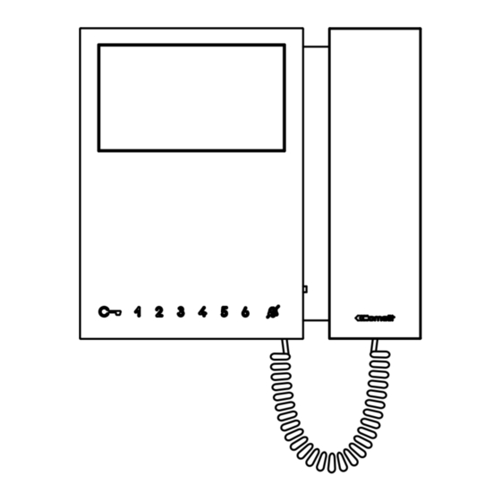
Description of the monitor The monitor can be used in Simplebus2 audio/video systems. • Art. 6701W is a colour monitor equipped as standard with 4 buttons. • Art. 6701W/BM is a colour monitor equipped as standard with 4 buttons and magnetic induction (Hearing loop) system. Not supplied with backplate 6710. -
Page 4: Description Of Buttons
Description of buttons f Press the desired button once to activate the associated function. Wait for approximately 1 sec. before pressing the same button again. Pressing the same button several times in quick succession will cancel the command. LOCK-RELEASE Use this key to open the corresponding door lock. ACTUATOR default (programmable*) Allows activation of the associated relay. -
Page 5: Technical Characteristics
Technical characteristics 6701W 6701W/BM 6701W/8 Product height (mm) Product width (mm) Product depth (mm) Product weight (g) Product color White RAL9003 White RAL9003 White RAL9003 Material Wall mounting Desk base-mounted Audio induction loop system LCD DISPLAY FEATURES Size (inches) 4.3" 16/9 4.3"... -
Page 6: Installation
Installation 17,5 cm optional fixing CLACK! CLACK! CLACK! -
Page 7: Removing / Fitting The Terminal
Removing / Fitting the terminal Connections 6701W 6701W/BM 6701W/8 VIDEO ENTRY SYSTEM RISER 1214/2C FLOOR DOOR CALL VIDEO ENTRY SYSTEM RISER 20 m MAX - Use shielded cable for the connection and do not route the cables in the vicinity of heavy inductive loads or power supply cables (230V/400V). -
Page 8: Monitor Configuration
Monitor configuration Main and secondary monitors In systems with art. 1209 or 1210, you can configure a maximum of 1 main monitor, while in systems with art. 4888C you can configure a maximum of 2 main monitors. To configure an internal unit as the main unit, set S2 DIP 8 to OFF To configure an internal unit as a secondary unit, set S2 DIP 8 to ON 1 2 3 4 1 2 3 4... -
Page 9: Button Configuration
(B-P) proposed in the table. All the buttons will change function. Basic configuration Mini 6701W/8 S2 Dip switches Mini 6701W - Mini 6701W/BM DIP 1 DIP 2 DIP 3 DIP 4... -
Page 10: Advanced Configuration
Advanced configuration If the standard configuration settings do not reflect requirements, the buttons can be programmed differently by carrying out the steps below. After programming, set S2 DIP switches 1-2-3-4 (PROG) to ON. With these DIP switch settings, the buttons manage the programmed functions. -
Page 11: Intercom Call To Selective Address: Button Programming
Intercom call to selective address: button programming √ It is necessary to carry out the 3 operations described in the paragraph "Assigning a selective address to the monitor". 1. Take note of the S1 DIP switch settings. 2. To enter programming mode, set S2 DIP switch 6 to ON. »... -
Page 12: Generic Actuator, Coded Actuator
Generic actuator, coded actuator Generic actuator: button programming 1. Take note of the S1 DIP switch settings. 2. To enter programming mode, set S2 DIP switch 6 to ON. » the LED switches on 3. Refer to the table “Basic configuration” and set on S2 a combination in which the Example: actuator function (ACT) associated with the buttons you wish to program appears. -
Page 13: Other Functions: Button Programming
Other functions: button programming 1. To enter programming mode, set S2 DIP switch 6 to ON. » the LED switches on 2. Refer to the table “Basic configuration” and set on S2 a combination in which the Example: function associated with the buttons you wish to program appears. 3. -
Page 14: Changing Monitor Ringtones
Changing monitor ringtones 1. Press and hold for 6 sec. » a confirmation tone will sound » the LED will flash to indicate "programming" mode. √ the procedure can only take place while the system is in standby; otherwise the LED will flash 4 times to inform the user that the system is busy. -
Page 15: Addressing Table
Addressing table DIP switch Cod. 1,2,3,4,5 1,3,4,5,6 1,2,4,5,7 1,4,5,6,7 1,2,3,5,8 1,3,5,6,8 1,2,5,7,8 2,3,4,5,6 3,4,5,7 2,4,5,6,7 4,5,8 2,3,5,6,8 3,5,7,8 1,2,3,4,5,6 1,3,4,5,7 1,2,4,5,6,7 1,4,5,8 1,2,3,5,6,8 1,3,5,7,8 2,3,4,5,7 3,4,5,6,7 2,4,5,8 4,5,6,8 2,3,5,7,8 1,2,6 1,2,3,4,5,7 1,3,4,5,6,7 1,2,4,5,8 1,4,5,6,8 1,2,3,5,7,8 2,3,4,5,6,7 3,4,5,8 2,4,5,6,8 4,5,7,8 1,2,3 1,3,6 1,2,7 1,6,7... - Page 16 C E R T I F I E D M A N A G E M E N T S Y S T E M S w w w . c o m e l i t g r o u p . c o m Via Don Arrigoni, 5 - 24020 Rovetta (BG) - Italy...