Advertisement
Quick Links
TVD-6120VE-2 / TVD-6125VE-2 Camera Quick
Start Guide
Introduction
This is the Quick Installation Guide for the TVD-6120VE-2-N(-
P)/ TVD-6125VE-2-N(-P) color dome camera.
Refer to the user manual for complete instructions on installing
and configuring this camera.
User guidelines
•
Program the camera settings as much as possible before
mounting the camera. Take appropriate safety precautions
while completing programming after installation.
•
Always use a 12 VDC or 24 VAC UL listed Class 2 power
supply to power the camera.
•
Do not use the camera over the temperature range
specifications: -10°C to +50°C (14°F to 122°F)
•
If the light source where the camera is installed
experiences rapid, wide- variations in lighting, the camera
may not operate as intended.
WARNING: To reduce the risk of fire or electronic shock, do
not expose the camera to rain or open the back of the camera.
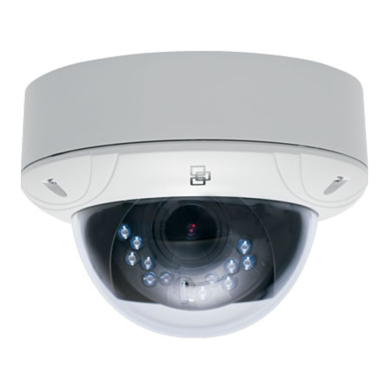
Description
Figure 1: Camera description
1.
Dome cover
2.
Screw hole
3.
Base
4.
OSD control button
5.
Lens
6.
IR LED
© 2012 UTC Fire & Security. All rights reserved.
7.
IR LED cover
8.
Outlet hole
9.
Power supply and video
BNC cables
10. Composite video BNC cable
11. Focus adjustment
12. Zoom adjustment
Installation
Please check the package contents and make sure that the
device in the package is in good condition and all the assembly
parts are included.
Note: Before installing, please ensure that the mounting
surface is strong enough to withstand three times the weight of
the camera. If the wall is not strong enough, the camera may
fall and cause serious damage.
Install the camera
1.
Remove the dome cover (see Figure 1).
2.
Secure the camera to the mounting surface with screws.
3.
Connect a 12 VDC or 24 VAC power supply to the power
input and connect a coaxial cable from the camera's BNC
connector to a CCTV monitor or video recording device.
4.
Adjust the lens:
Remove the IR LED cover to adjust the lens and the
viewing angle.
Rotate the panning table to adjust the panning position of
the camera.
Lens rotation 0-355°
Panning table 0-355°
Rotate the tilting table to adjust the tilting position of the
camera.
Rotate the lens to adjust the azimuth angle of the image.
Adjust the lens to obtain the appropriate angle of view and
the optimum focus. Tighten the focus lock lever.
5.
Replace the IR LED and dome covers on the camera.
6.
Secure the dome cover with screws.
Note: Ensure that the screws have been tightened securely to
prevent water seepage.
1 / 2
Tilting table 0-75°
P/N 1072542B-EN • ISS 21JUN12
Advertisement

Related Manuals for Interlogix TVD-6120VE-2-N


Summary of Contents for Interlogix TVD-6120VE-2-N
- Page 1 Start Guide Introduction Installation This is the Quick Installation Guide for the TVD-6120VE-2-N(- Please check the package contents and make sure that the P)/ TVD-6125VE-2-N(-P) color dome camera. device in the package is in good condition and all the assembly parts are included.
- Page 2 Moves the cursor to the right to select or adjust Specifications the parameters of the selected item. Down Moves the cursor downward to select an item. Model TVD-6120VE-2-N(P) TVD-6125VE-2-N(P) Enter Press the center of the control pad to display the Power supply 24 VAC / 12 VDC 24 VAC / 12 VDC Setup menu.