
Related Manuals for Interlogix TVB-5501


Summary of Contents for Interlogix TVB-5501
-
Page 1: Camera Installation
TruVision Series 5 IP Camera Installation Guide P/N 1073339-EN • REV B • ISS 13SEP17... - Page 2 Copyright © 2017 United Technologies Corporation, Interlogix is part of UTC Climate, Controls & Security, a unit of United Technologies Corporation. All rights reserved. Trademarks and Trade names used in this document may be patents trademarks or registered trademarks of the manufacturers or vendors of the respective products.
- Page 3 (1) This device may not cause harmful interference. (2) This Device must accept any interference received, including interference that may cause undesired operation. ACMA compliance Notice! This is a Class A product. In a domestic environment this product may cause radio interference in which case the user may be required to take adequate measures.
- Page 4 (Cd), lead (Pb), or mercury (Hg). For proper recycling, return the battery to your supplier or to a designated collection point. For more information see: www.recyclethis.info. Contact information For contact information, see www.interlogix.com or www.utcfssecurityproducts.eu.
-
Page 5: Table Of Contents
Content Introduction 2 Product overview 2 Installation 3 Installation environment 3 Package contents 4 Cable requirements 10 Camera description 11 Setting up the camera 13 IR illuminators 13 Accessing the SD card 14 Mounting the bullet camera 14 Mounting the turret camera 15 Mounting the dome camera 18 Using the camera with a TruVision recorder or another system 22... -
Page 6: Introduction
Introduction Product overview This is the installation guide for TruVision Series 5 IP camera models: TVB-5501 (3MPX IP bullet camera) TVB-5502 (8MPX IP bullet camera) TVT-5501 (3MPX IP turret camera) TVT-5502 (8MPX IP turret camera) TVD-5501 (3MPX IP dome camera) ... -
Page 7: Installation
Installation This section provides information on how to install the cameras. Installation environment When installing your product, consider these factors: • Electrical: Install electrical wiring carefully. It should be done by qualified service personnel. Always use a proper PoE switch or a 12 VDC UL listed Class 2 or CE certified power supply to power the camera. -
Page 8: Package Contents
• Cleaning: Do not touch the sensor modules with fingers. If cleaning is necessary, use a clean cloth with some ethanol and wipe the camera gently. If the camera will not be used for an extended period of time, put on the lens cap to protect the sensors from dirt. - Page 9 • Screws • CD with Configuration manual and TruVision Drywall anchor Device Manager 7.5 × 24.5 mm (3 pcs) Screw M4 × 25 mm (3 pcs) • Installation manual • Equipment Disposal Sheet • Battery Disposal Sheet • Torx wrench Installation Guide...
- Page 10 IP turret camera • Camera • 12 VDC connector: Two terminal connector with positive and negative indicators. • Camera drill template • Water joint: Provides water resistance to network cable connector. Adapter plate • • Screws Drywall anchor 7.5 × 24.5 mm (4 pcs) Screw M4 ×...
- Page 11 • CD with Configuration • Screw PM4 × 8 (3pcs) manual and TruVision Device Manager • Screw PM6-32 × 10 • Screw KM4 × 8 (4 pcs, (4 pcs, used to attach used to attach the the turret camera to a 2 adapter to the Gang electrical box) brackets)
-
Page 12: Ip Dome Camera
• Battery Disposal Sheet IP dome camera • Camera • 12 VDC connector: Two terminal connector with positive and negative indicators. • Screws Camera drill template • Drywall anchor 7.5 × 24.5 mm (3 pcs) Screw M4 × 25 mm (3 pcs) Installation Guide... - Page 13 • Torx wrench • Water joint: Provides water resistance to network cable connector. • Toggle bolt (3 pcs) • Gray cloth • CD with Configuration • Installation manual manual and TruVision Device Manager Installation Guide...
-
Page 14: Cable Requirements
• Equipment Disposal • Battery Disposal Sheet sheet Caution: Use direct plug-in UL listed power supplies marked Class 2/CE certified or LPS (limited power source) of the required output rating as listed on the unit. Caution: Risk of explosion if the battery is replaced by an incorrect type. -
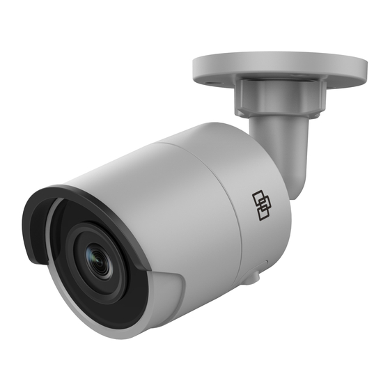
Page 15: Camera Description
Camera description Figure 1: IP bullet camera Adjustable bracket 12 VDC power Back housing Reset button Front housing SD card slot Lens 10. Grounding screw Sunshield 11. Serial port (factory use) Ethernet RJ45 PoE port Note: To reset the camera to default settings, press and hold the RESET button and power on the camera. - Page 16 Figure 2: IP turret camera Lens assembly Base Trim ring 12 VDC power Housing Ethernet RJ45 PoE port Figure 3: IP dome camera 12 VDC power Base Audio I/O Dome liner Alarm I/O Lens Ethernet RJ45 PoE port Housing cover Installation Guide...
-
Page 17: Setting Up The Camera
Setting up the camera Note: If the light source where the camera is installed experiences rapid, wide-variations in lighting, the camera may not operate as intended. To quickly put the camera into operation: Prepare the mounting surface. Mount the camera on the mounting surface using the appropriate fasteners. -
Page 18: Accessing The Sd Card
Note: Avoid installing the IR camera closely facing a solid object such as a tree or wall. The reflection will cause over- exposure and loss of visibility of detail in field of view. Accessing the SD card Insert a Micro SD card with up to 128GB to use the camera as an additional recording device, or as a backup in case of failure of communication with the network video recorder (see Figure 1 on page 11). -
Page 19: Mounting The Turret Camera
Loosen the large nut at the base of the mounting bracket to adjust the camera’s viewing angle. Pan direction: 0 to 360° adjustable Tilt direction: 0 to 90° adjustable Rotate direction: 0 to 360° adjustable Adjust the lens to the desired surveillance angle. Tighten the adjustable nuts to complete the installation. - Page 20 If installing the turret camera to a wall mount or other accessory, an adapter plate is provided. Install the adapter plate to the accessory with three PM4X8 screws, referencing number “2”. Rotate the trim ring counterclockwise to remove it from the camera.
- Page 21 Rotate the lens assembly to adjust the pan angle. Rotate the lens assembly to adjust the tilt angle. Tighten the locking screw to secure the lens at the desired surveillance angle. Locking screw Attach the trim ring to the camera and rotate it clockwise to secure it.
-
Page 22: Mounting The Dome Camera
Mounting the dome camera To mount the dome camera on a ceiling or wall: Place the drill template (supplied) on the surface where the camera is to be mounted. Drill mounting holes in the surface using the holes labeled number ‘1’ on the drill template. - Page 23 Screw Install the dome on the mounting surface using the supplied hardware. Installation Guide...
- Page 24 Loosen the tilt adjust screws (see image below) and adjust the tilt position of the lens assembly within a range of 75 degrees. Retighten the tilt adjust screws. Rotate the dome liner to adjust the pan position within a range of 355 degrees. Rotate the lens assembly (0 to 355°) to obtain the desired surveillance angle.
- Page 25 (Optional) If using a micro SD card (not included): To remove the SD card, push the micro SD card forward. The micro SD card will spring out. SD slot Reinstall the dome housing and tighten the Torx screws. Installation Guide...
-
Page 26: Using The Camera With A Truvision Recorder Or Another System
Using the camera with TruVision Navigator A camera must be connected to an Interlogix NVR in order to be operated by TruVision Navigator. Please refer to the TruVision Navigator user manual for instructions on operating the camera with TruVision Navigator. -
Page 27: Truvision Ip Turret Dome
Environmental rating IP67 TruVision IP turret dome Electrical Voltage input 12 VDC, PoE (IEEE 802.3af) Power consumption 3MPX: Max. 7 W 8MPX: Max. 7 W Miscellaneous Connectors 12 VDC Power Input, Network Port (PoE) Operating temperature -30 to +60 °C (-22 to +140 °F) Dimensions 127.3 ×... -
Page 28: Pin Definitions
Dimensions 111 × 82.4 mm (4.4 × 3.2 in.) Weight 500 g (1.1 lbs.) Environmental rating IP67, IK10 Pin definitions There are eight wires on a standard UTP/STP cable and each wire is color-coded. The following shows the pin allocation and color of straight and crossover cable connection: Figure 4: Straight-through cable White/Orange... - Page 29 Figure 5: Cross-over cable White/Orange White/Orange Orange Orange White-Green White-Green Blue Blue White/Blue White/Blue Green Green White/Brown White/Brown Brown Brown Please make sure your connected cables have the same pin assignment and color as above before deploying the cables in your network.